Gebrauchsanleitung Manual Mode d'Emploi
Gebrauchsanleitung Manual Mode d'Emploi
Gebrauchsanleitung Manual Mode d'Emploi

You also want an ePaper? Increase the reach of your titles
YUMPU automatically turns print PDFs into web optimized ePapers that Google loves.
<strong>Gebrauchsanleitung</strong><br />
<strong>Manual</strong><br />
<strong>Mode</strong> d’Emploi<br />
Digital-Form-Hauptsignal<br />
Digital Main Semaphore<br />
Signal principal numérique<br />
Hp0 / Hp2<br />
Anleitung Deutsch .......................... 2 – 3<br />
Instruction <strong>Manual</strong> English ............. 4 – 5<br />
<strong>Mode</strong> d‘Emploi Français ................ . 6 – 7<br />
Fig. 1 – 3 ........................................ 8 – 9<br />
Fig. 4 – 5 ........................................ 10 – 11<br />
4701 (H0)
D<br />
2<br />
Digital-Form-Hauptsignal<br />
Hp0 / Hp2<br />
Lesen Sie vor der ersten Benutzung des<br />
Produktes bzw. dessen Einbau die Be dienungs<br />
anleitung aufmerksam durch. Das<br />
Produkt darf ausschließlich dieser Anleitung<br />
gemäß verwendet werden.<br />
Das Signalmodell ist konstruiert zum Einbau<br />
in <strong>Mode</strong>lleisenbahnanlagen und zum<br />
Anschluss an einen zugelassenen Mo dellbahn<br />
trans formator bzw. an einer damit versorgten<br />
elektrischen (digitalen) Steuerung in<br />
trockenen Räumen.<br />
Jeder darüber hinausgehende Gebrauch gilt<br />
als nicht bestimmungsgemäß. Für hieraus<br />
resultierende Schäden haftet der Hersteller<br />
nicht; das Risiko hierfür trägt allein der<br />
Benutzer.<br />
Einleitung<br />
Viessmann-Digital-Formsignale zeichnen sich<br />
durch ihr hervorragendes Preis-Leistungs-<br />
Verhältnis sowie durch einfache Montage und<br />
Anschlussmöglichkeit aus! Im angesetzten<br />
Antriebskasten befinden sich der Spezialantrieb<br />
zur Erzeugung der typischen langsamen<br />
Bewegung, der Digitaldecoder sowie der Kontakt<br />
für die Zugbeeinflussung. Das Motto heißt<br />
„Auspacken, Anschließen und Losfah ren“.<br />
Elektrische Vorkenntnisse sind nicht notwendig!<br />
Die Digital-Form-Haupt sig na le können so wohl<br />
separat, als auch in Kombi na tion mit Digital-Form-<br />
Vor- oder Sperr sig na len aufgestellt werden.<br />
Aufstellung von Form-<br />
Hauptsignalen<br />
Hauptsignale stehen in Deutschland in der Regel<br />
in Fahrtrichtung gesehen rechts vom Gleis.<br />
Zweiflügelige Form-Hauptsignale können als<br />
Ein- oder Ausfahrsignale im Bahnhofsbereich eingesetzt<br />
werden, wenn die Ein- bzw. Ausfahrt nicht<br />
mit der Strecken höchstgeschwindigkeit befahren<br />
werden darf. Das ist normalerweise dann gegeben,<br />
wenn der Zug über mindestens eine abzweigende<br />
Weiche fahren muss.<br />
Bezeichnung von Hauptsignalen<br />
Damit ein Lokführer Signale richtig zuordnen kann<br />
oder auch im Störungsfall die richtige Meldung<br />
machen kann, werden die Signale mit einer<br />
Buchstaben-Zahlenkombination gekennzeichnet.<br />
Die Bezeichnung des Signals gibt zusätzlich<br />
Auskunft über seinen Standort. Hier sind einige<br />
Richtlinien zur korrekten Beschrif tung von<br />
Blocksignalen und Ausfahrsignalen:<br />
Einfahrsignale:<br />
In Rich tung der Kilometrierung der Strecke<br />
werden die Signale mit den Buchstaben A bis<br />
E beschriftet, in der Gegenrichtung mit F bis K.<br />
Gibt es nur ein Einfahrgleis je Richtung, so tragen<br />
die zugehörigen Signale die Buchstaben A und F.<br />
Werden mehrere Gleise benutzt, fahren Sie in der<br />
Nomenklatur fort: bei z.B. drei Gleisen in Richtung<br />
der Kilometrierung und zwei in der Gegenrichtung<br />
lauten die Bezeichung A, B, C und F, G.<br />
Ausfahrsignale:<br />
In Rich tung der Kilometrierung der Strecke werden<br />
die Signale mit den Buchstaben N gekennzeichnet,<br />
die Ausfahrsignale der Gegenrichtung<br />
mit P. Hinter dem Buchstaben steht die Ziffer des<br />
Gleises, für welches das Signal gilt.<br />
Damit Sie Ihre Signale korrekt beschriften können,<br />
liegt dem Signal eine Tafel mit selbstklebenden<br />
Bezeichnungsschildern bei. Schnei den Sie das<br />
gewünschte Schild aus, ziehen Sie die Schutzfolie<br />
ab und kleben Sie es auf die Num merntafel am<br />
Mast des Signals (Fig. 5 auf Seite 11).<br />
Funktionskontrolle<br />
Bevor Sie das Signal in Ihre Anlage einbauen,<br />
sollten Sie eine Funk tionskontrolle durchführen.<br />
Dazu schließen Sie es provisorisch an die<br />
Digitalsteuerung an (siehe Fig. 1 auf Seite 8),<br />
programmieren seine Adresse und schalten es<br />
abwechselnd auf ‘rot’ und ‘grün’. Das Signal sollte<br />
dabei folgende Bilder zeigen:<br />
auf ‘rot’ geschaltet<br />
Hp0 „Halt“<br />
auf ‘grün’ geschaltet<br />
Hp2 „Fahrt<br />
mit begrenzter<br />
Geschwindigkeit“
Anschluss des Signals<br />
Das Digital-Signal ist mit einem Antrieb ausgerüstet,<br />
der einen Digitaldecoder enthält. Er<br />
eignet sich sowohl für das Märklin/Moto rola-<br />
Format als auch für das NMRA-DCC-Format.<br />
Dadurch ist der Anschluss des Signals beson ders<br />
einfach. Sie haben zwei Möglichkeiten für die<br />
Stromversorgung des Signals.<br />
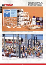
Fig. 1 auf Seite 8 zeigt die Versorgung des<br />
Signals ausschließlich aus einem Digitalsystem.<br />
Fig. 2 auf Seite 9 benutzt zur Strom versorgung des<br />
Antriebs einen separaten Trafo. Das entlastet das<br />
Digitalsystem und wird zur Anwendung empfohlen.<br />
Dieser Trafo darf dann keine Digital-Zentrale<br />
oder Booster mit Strom versorgen!<br />
Der eingebaute Schaltkontakt (d.h. die beiden<br />
roten Anschlusskabel) der Digital-Formsignale<br />
kann für die Steuerung des Fahr stroms und damit<br />
zur automatischen Zug beein flussung genutzt<br />
werden.<br />
Programmierung der Adresse<br />
Ein digitales Zubehör benötigt eine Adresse, damit<br />
die Steuerung es von anderen unterscheiden und<br />
so gezielt ansprechen kann. Diese Adresse erhält<br />
das Digital-Signal durch die Programmierung.<br />
Dazu schließen Sie das Signal provisorisch an<br />
Ihre Digitalsteuerung an. Drücken Sie dann mit<br />
einem Kugelschrei ber in die kleine Öffnung links<br />
am Antriebs kas ten des Signals.<br />
Beim ersten Tastendruck ist der Decoder bereit<br />
für eine Program mierung im Märklin/Moto ro la-<br />
Format: Als Zeichen dafür schaltet das Signal<br />
drei Mal langsam hin und her. Nach dem zweiten<br />
Tastendruck ist es be reit für das NMRA-DCC-<br />
Format. Das Signal schaltet drei Mal schnell hin<br />
und her.<br />
Geben Sie jetzt mit Ihrer Digitalsteuerung mit der<br />
gewünschten Adresse einen Schaltbefehl für das<br />
Signal. Eine erfolgreiche Program mie rung bestätigt<br />
das Signal mit einem dreimaligen langsamen<br />
Hin- und Herschalten.<br />
Mit einem dritten Tastendruck, ohne vorheriges<br />
Senden eines Schaltbefehls, wird der Pro grammiermodus<br />
wieder verlassen – ohne Reaktion des<br />
Signals. Die alte Adresse bleibt dann erhalten.<br />
Beim NMRA-DCC-Modus gibt es auch die Möglichkeit,<br />
das Signal auf eine Lok adres se zu programmieren<br />
und es dann mit den Tasten F1 bis<br />
F4 zu schalten, z.B. bei der Lokmaus 2 von Roco.<br />
Für diesen Programmiermodus ist es wichtig,<br />
dass vor der Programmierung die Digi talzentrale<br />
aus- und wieder eingeschaltet wird, damit sich<br />
keine Loks mit eingeschalteter Funktion im<br />
Sendepuffer der Zentrale befinden. Ansonsten<br />
würde sich das Digital -Hauptsignal sofort nach<br />
Eintritt in den DCC-Adress pro gram miermodus<br />
auf den erstbesten Lokbefehl mit eingeschalteter<br />
F-Taste einstellen und wäre dadurch auf diese<br />
Adresse programmiert.<br />
Kombination mit einem<br />
Vorsignal<br />
Ein Vorsignal macht den Lokomotivführer bereits<br />
eine Weile vorher auf das Signalbild aufmerksam,<br />
welches ihn am nächsten im Fahrweg liegenden<br />
Hauptsignal erwartet. Das Vorsignal eines<br />
Hauptsignals mit zwei gekoppelten Flügeln zeigt<br />
also entweder „Fahrt mit Geschwindigkeitsbeschränkung<br />
erwarten“ (Vr2) oder „Halt erwarten“<br />
(Vr0) an. Beim Vorbild stehen Vorsignale entweder<br />
400 m, 700 m oder 1.000 m vor dem Hauptsignal,<br />
je nach zulässiger Höchstgeschwindigkeit und<br />
Be schaffenheit der Strecke.<br />
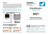
Das Digital-Form-Hauptsignal 4701 wird am besten<br />
in Kombination mit einem Digital-Vor si g nal<br />
4710 angeordnet (siehe Fig. 4 auf den Seiten<br />
10 und 11). Dazu werden beide Signale auf die<br />
gleiche Digi tal adresse programmiert. So werden<br />
sie gemeinsam mit nur einem Tastendruck gestellt<br />
und zeigen immer die richtigen Signalbilder an.<br />
Technische Daten<br />
Digitalformate: NMRA-DCC bzw.<br />
Märklin/Motorola<br />
Stromaufnahme im<br />
Schaltmoment (ca. 0,1 s): 0,7 A<br />
Maximale Belastbarkeit<br />
des Fahrstromkontaktes: 2,0 A<br />
Abmessungen des<br />
Antriebskastens: 49,6 x 20,4 x 13,1 mm 3<br />
(Länge x Breite x Höhe)<br />
D<br />
3
GB<br />
4<br />
Semaphore Main Signal Hp0 / Hp2<br />
Read the operating instructions and these<br />
supplementary instructions carefully before<br />
using the product for the fi rst time or installing<br />
it. This product may only be used for the<br />
intended purpose as outlined in this manual.<br />
This model of a railway signal has been<br />
designed for the installation in model train<br />
layouts and must be connected to an approved<br />
transformer for model trains or a<br />
digital command control system which is<br />
powered by such a transformer in rooms<br />
with low humidity. Any other use is considered<br />
unsuitable and the manufacturer is not<br />
liable for any consequential damage.<br />
Introduction<br />
Viessmann digital semaphore signals are affordable<br />
and easy to install mechanically and electrically.<br />
The special low-speed-drive is located in the<br />
housing fi xed to the signal which also contains the<br />
digital decoder as well as the contacts for switching<br />
the power to the insulated rail section in front<br />
of the signal. It is a true “plug-and-play” item; no<br />
electrical knowledge is required.<br />
The digital semaphore main signals can be used<br />
alone or in conjunction with digital semaphore<br />
distant signals or semaphore stop signals.<br />
Placement of Semaphore Main<br />
Signals<br />
In Germany main signals (home or exit signals)<br />
are generally located on the right hand side of<br />
the track when viewed in the direction of travel.<br />
Semaphore signals with two indicating arms may<br />
be used as home- or exit signals in a station<br />
whenever train movements have to be undertaken<br />
at reduced speed. Normally this is the case if the<br />
train travel over a point set to the diverging route.<br />
Description of Main Signals<br />
In order to enable the engineer to recognize<br />
signals correctly and to report any faults, all<br />
signals bear a combination of letters and numbers<br />
as identifi cation. This identifi cation also provides<br />
information regarding its location. Here are some<br />
guidelines for the appropriate naming/numbering<br />
of home signals and exit signals:<br />
Home signals:<br />
In the direction of increasing distance markers<br />
along the main line signals are marked with the<br />
letters ‘A‘ to ‘E‘, in the opposite direction with ‘F‘ to<br />
‘K‘. If there is only one home signal in each direction,<br />
these signals are marked with ‘A‘ and ‘F‘. If<br />
several signals are used for the same direction<br />
of travel add the appropriate subsequent letter:<br />
e.g. if there are three tracks used in the direction<br />
of counting and two in the opposite direction the<br />
signals will be marked ‘A‘, ‘B‘, ‘C‘ and ‘F‘, ‘G‘.<br />
Exit signals:<br />
Exit signals located in the direction of counting<br />
are marked with ‘N‘. Exit signals facing the other<br />
way are marked with ‘P‘. After the letter ‘N‘ or ‘P‘<br />
follows the track number to which the signal is<br />
assigned. To be able to mark your signals as per<br />
prototype rules adhesive signs are supplied with<br />
the signal. Cut out the appropriate sign, remove<br />
the protective cover and stick it onto the number<br />
plate on the signal mast (see fi g. 5 on page 11).<br />
Function test<br />
Prior to installing the signal you should test all<br />
functions of the signal. Connect the signal to the<br />
DCC system temporarily (see fi g. 1 on page 8),<br />
program the desired address and switch from red<br />
to green and vice versa several times. The signal<br />
should show the following aspects:<br />
set to ‘red’<br />
Hp0 ‘stop‘<br />
Connecting the Signal<br />
set to ‘green’<br />
Hp2 ‘reduced<br />
speed‘<br />
The main signal 4701 is equipped with a slowspeed-drive<br />
and the digital decoder. The decoder<br />
is suitable for operation with the Märklin-/Motorola<br />
format as well as with any DCC system as per<br />
NMRA. Therefore connecting the signal is almost<br />
child’s play. There are two options for supplying<br />
power to the signal solely from the digital system<br />
as shown in fi g. 1 on page 8 or you may choose<br />
the better option as shown in fi g. 2, namely to<br />
utilize a separate power supply and thus reduce<br />
the load drawn from the digital system.<br />
This transformer may not be used as the<br />
power supply for the digital command station<br />
or a booster!
The integral contact connected to the two red<br />
wires can be used for switching the track power<br />
and therefore for automatic train control.<br />
Programming of the address<br />
Every digital device requires an address in order<br />
to allow the command control station or any other<br />
input device to send specifi c commands. The<br />
desired address has to be programmed. In order<br />
to do this, connect the signal to the digital system<br />
temporarily. Now you have to switch the decoder<br />
into programming mode. Push a ball point pen into<br />
the small opening of the signal drive.<br />
If you push once the decoder is ready for programming<br />
in the Märklin-/Motorola format: The signal<br />
slowly changes its aspect three times as confi rmation.<br />
A second push with the pen and the decoder<br />
is ready for the NMRA-DCC format. The signal<br />
changes ist aspect three times – this time very<br />
rapidly.<br />
Enter the desired address and switch the signal.<br />
Now the signal has been programmed and<br />
confi rms this by slowly changing its aspect three<br />
times.<br />
If you use the pen a third time, without sending a<br />
switching command beforehand, the signal returns<br />
to normal operating mode. The address is not<br />
changed.<br />
In the NMRA-DCC mode the signal can also be<br />
programmed to a locomotive address which can<br />
then be activated by pushing one of the function<br />
buttons ‘F1‘ – ‘F4‘. This may be used with the<br />
Roco Lokmaus 2. To avoid any unwanted side<br />
effects it is important to switch off the command<br />
station prior to programming. Otherwise the digital<br />
signal would respond to the fi rst command for a<br />
locomotive with active ‘F‘ button and would be<br />
programmed to this particular address.<br />
Main signal and distant signal<br />
The distant signal alerts the engineer about the<br />
aspect of the main signal long before the latter can<br />
be seen. The distant signal of a main signal with<br />
two linked indicating arms shows either “proceed<br />
at reduced speed (Vr2)” or “stop at main signal<br />
(Vr0)”. Depending on the permitted maximum<br />
speed and the general condition of the line,<br />
prototype distant signals are located either 400 m,<br />
700 m or 1,000 m before the main signal to which<br />
they are assigned.<br />
It is recommended to use the digital main signal<br />
4701 in conjunction with a digital distant signal<br />
4710 (see fi g. 4 on the pages 10 and 11). Both signals<br />
are programmed to the same address. Thus<br />
they are controlled by the same button and always<br />
show the corresponding aspect.<br />
Technical Specifications<br />
Digital formats: NMRA-DCC and<br />
Märklin/Motorola<br />
Current consumption<br />
in the moment<br />
of action (< 0,1 s): 0.7 A<br />
Maximum load for<br />
the relay contacts: 2.0 A<br />
Dimensions of the<br />
signal motor box: 49.6 x 20.4 x 13.1 mm 3<br />
(length x width x height)<br />
GB<br />
5
F<br />
6<br />
Sémaphore principal à commande<br />
numérique Hp0 / Hp2<br />
Lisez attentivement ce mode d’emploi avant<br />
de monter et d’exploiter ce produit pour la<br />
première fois.<br />
L’utilisation de ce produit doit absolument<br />
être conformément à ce mode d’emploi.<br />
Ce modèle réduit de signal est conçu en<br />
vue d’une installation sur des réseaux de<br />
trains miniatures dans des pièces sèches<br />
et d’un raccordement à une unité centrale<br />
numérique raccordée à un transformateur<br />
agréé pour des réseaux de trains miniatures.<br />
Tout autre usage n’est pas conforme<br />
aux dispositions. La responsabilité du fabricant<br />
n’est pas engagée en cas d’utilisation<br />
non conforme à ce mode d’emploi.<br />
Préface<br />
Les sémaphores à commande numérique de<br />
« Viessmann » se caractérisent par un excellent<br />
rapport qualité-prix, de même que par un assemblage<br />
et raccordement simple ! L’entraînement<br />
spécial qui génère le mouvement typiquement<br />
lent, le décodeur numérique et le contact pour la<br />
commande de l’arrêt automatique des trains, se<br />
trouvent dans le boîtier de commande au sol. Le<br />
slogan est: « déballer, raccorder et démarrer ! ».<br />
Des connaissances préliminaires en électricité ne<br />
sont pas nécessaires ! Les sémaphores d’arrêt<br />
à commande numérique peuvent être implantés,<br />
soit associés à un sémaphore d‘avertissement ou<br />
à un sémaphore d’arrêt à commande numérique,<br />
soit séparément.<br />
L’emplacement des sémaphores<br />
signaux principaux<br />
En Allemagne, les signaux principaux se trouvent<br />
normalement à droite de la ligne, regardant dans<br />
le sens de la marche. En ligne, les sémaphores<br />
principaux à deus ailes peuvent être installés en<br />
qualité de signaux de bloc et aux abords de la<br />
gare en qualité de signaux d’entrée ou de sortie,<br />
dans le cas ou la circulation sur la voie de départ<br />
est autorisé à vitesse limitée. C’est normalement<br />
le cas, si le train doit passer par un aiguillage.<br />
Identifi cation des signaux principaux<br />
Afin que le conducteur de locomotive puisse bien<br />
identifier le type de signal rencontré ou transmettre<br />
un message approprié en cas d’incident,<br />
les signaux sont marqués d’une combinaison de<br />
lettres et de chiffres. Les indications sur le signal<br />
donnent en outre des informations sur l’endroit où<br />
il se trouve.<br />
Voilà quelques directives pour l’étiquetage approprié<br />
de signaux d’entrée ou de sortie :<br />
Voilà quelques directives pour l’étiquetage approprié<br />
de signaux d’entrée et de sortie :<br />
Les signaux d’entrée :<br />
implantés dans le sens du kilométrage de lignes,<br />
sont marqués de lettres de A à E, et ceux en sens<br />
inverse de lettres de F à K.<br />
Dans le cas ou il n’y a qu’une seule voie d’entrée<br />
par direction, les signaux qui y sont attribués<br />
sont marqués d’un « A » et d’un « F ». Dans une<br />
exploitation de plusieurs voies, vous continuez la<br />
nomenclature. Exemple : en cas de 3 voies dans<br />
le sens du kilométrage de lignes et de 2 voies<br />
en sens inverse, la désignation sera « A », « B »,<br />
« C » et « F », « G »<br />
Les Signaux de sortie :<br />
implantés dans le sens du kilométrage de lignes,<br />
sont marqués d’un « N ».<br />
Les signaux de sortie en sens inverse, sont marqués<br />
d’un « P ».<br />
Le chiffre après la lettre, désigne la voie à laquelle<br />
le signal est affecté. En vue d’un étiquetage correct<br />
de vos signaux, des étiquettes autocollantes<br />
et une plaque font part de la fourniture. Découpez<br />
l’étiquette appropriée, enlevez la pellicule protectrice,<br />
et collez-la sur la plaque d’identification,<br />
qui est accolée au mat du signal (voir l’illustration<br />
n o 5, page 11).<br />
Contrôle du fonctionnement<br />
Contrôlez toujours le fonctionnement du signal<br />
avant de le monter. A ces fins vous le raccordez<br />
provisoirement à la commande numérique (voir<br />
l’illustration n o 1, page 8). Programmez ensuite<br />
son adresse et commutez- le à tour de rôle sur<br />
« rouge » et « vert ». Le signal devrait alors représenter<br />
les indications suivantes :<br />
Commuté sur «rouge»<br />
Hp0 «arrêt absolu»<br />
commuté sur «vert»<br />
Hp2 «marche à<br />
vitesse réduite»
Le raccordement du signal<br />
L’entraînement du signal principal, réf. 4701 est<br />
muni d’un décodeur à commande numérique.<br />
Il reconnaît aussi bien le protocole du format<br />
« Märklin/Motorola », que celui du format normalisé<br />
NMRA « DCC ». Le raccordement du signal est<br />
donc très simple. Quant à l’alimentation en courant<br />
de votre signal vous avez deux possibilités.<br />
L’illustration n o 1 à la page 8, figure l’alimentation<br />
du signal, qui est exclusivement effectuée par le<br />
système à commande numérique. L’illustration<br />
n o 2 à la page 9 représente une meilleure solution,<br />
c’est-à-dire l’alimentation de l’entraînement<br />
du signal par un transformateur autonome, en vue<br />
de décharger le système à commande numérique.<br />
Impératifs : ce transformateur ne doit pas être utilisé<br />
pour l’alimentation d’une commande numérique<br />
ou bien d’un amplificateur complémentaire.<br />
L’entraînement dispose d’un interrupteur de fin de<br />
course. Un contact de commande incorporé (les<br />
deux câbles de raccordements rouges), peut être<br />
exploité pour la commande du courant de traction<br />
en vue d’un pilotage en mode d’exploitation<br />
« arrêt automatique des trains ».<br />
La programmation de l’adresse<br />
Un accessoire à commande numérique doit<br />
avoir sa propre adresse, afin que l’unité centrale<br />
puisse différencier les appareils et communiquer<br />
directement avec eux. Une programmation assure<br />
l’assignation d’adresse au signal d’arrêt, réf.4701.<br />
À ces fins vous raccordez le signal provisoirement<br />
à la commande numérique. Vous enfoncez<br />
ensuite un stylo dans le petit trou qui est sur la<br />
face latérale droite du boîtier de commande du<br />
signal. Le premier<br />
appui sur<br />
la touche incorporée<br />
commute<br />
le décodeur au<br />
mode de programmation<br />
du<br />
format « Märklin/<br />
Motorola ». En signe de confirmation, le signal<br />
exécute un triple changement lent des positions.<br />
Le deuxième appui commute le décodeur au<br />
mode de programmation du format « DCC »<br />
NMRA. Le signal commute trois fois rapidement.<br />
Entrez ensuite, par votre système à commande<br />
numérique, une instruction d’enclenchement pour<br />
le signal, en utilisant l’adresse prévue. Le signal<br />
confirmera une programmation correcte par un<br />
triple changement lent des aspects. Afin de quitter<br />
le mode de programmation, sans modification,<br />
vous appuyez une troisième fois sur la touche<br />
– le signal ne réagira pas. L’ancienne adresse<br />
subsiste.<br />
En programmation au format « DCC » NMRA,<br />
vous avez en outre la possibilité de programmer le<br />
signal sur une adresse de locomotive et de l’activer<br />
en appuyant sur les touches fonctions F1 – F4, p.e<br />
par la Lokmaus 2 (Loc-Souris type 2) de ROCO.<br />
Ce mode de programmation exige que vous<br />
éteigniez d’abord l’unité centrale numérique et la<br />
rallumiez ensuite, avant de commencer la programmation<br />
proprement dite, ceci afin d’éviter que<br />
des locomotives dont les fonctions supplémentaires<br />
activées se trouvent dans la bande d’émission<br />
de la mémoire tapon de l’unité centrale. Car en ce<br />
cas, le sémaphore principal numérique répondrait<br />
à la première commutation d’une locomotive avec<br />
la fonction F activée. Le signal serait alors automatiquement<br />
programmé sur cette adresse.<br />
L’interconnexion avec un sémaphore<br />
d’avertissement<br />
Un sémaphore d’avertissement prévient le conducteur<br />
un certain temps d’avance de l’aspect affiché<br />
au prochain signal principal qu’il rencontrera.<br />
L’avertissement qui est associé à un signal principal<br />
à une aile, annoncera alors « voie libre au prochain<br />
signal »(Vr1) ou « prochain signal fermé »(Vr0).<br />
Dans la réalité ferroviaire la distance entre un<br />
signal principal et son avertissement se porte à<br />
400m, 700m ou 1.000m, en fonction de la limite de<br />
vitesse en ligne et des conditions de la ligne.<br />
Le sémaphore principal commande numérique,<br />
réf.4701, se prête surtout à une interconnexion<br />
avec le sémaphore d’avertissement commande<br />
numérique, réf.4710 (voir l’illustration n o 4, pages<br />
10/11). A ces fins vous programmez les deux<br />
signaux sur la même adresse. Un seul appui sur<br />
une touche les activera tous les deux simultanément<br />
et leurs aspects seront toujours coordonnés.<br />
Caractéristiques techniques<br />
Format de régime : «DCC» / NMRA<br />
ou «Märklin/Motorola»<br />
Consommation lors de<br />
la commutation<br />
(env. 0,1 sec.) : 0,7 A<br />
Capacité maximale de<br />
charge du contact pour<br />
le courant de traction : 2,0 A<br />
Dimensions du boîtier<br />
de commande : 49,6 x 20,4 x 13,1 mm 3<br />
(longueur x largeur x<br />
hauteur)<br />
F<br />
7
8<br />
Alle Anschluss- und Montagearbeiten dürfen nur bei abgeschalteter Betriebsspannung durchgeführt<br />
werden! Die Stromquellen müssen so abgesichert sein, dass es im Falle eines Kurzschlusses<br />
nicht zum Kabelbrand kommen kann. Verwenden Sie nur nach VDE / EN gefertigte <strong>Mode</strong>llbahntransformatoren<br />
und Kabel mit ausreichendem Querschnitt!<br />
Installation and electrical connection must only be carried out if the digital system and any other<br />
powered device on the layout is disconnected! Any power supply must be protected in such a<br />
manner that the wiring cannot burn even in the event of a short circuit. Only use transformers<br />
suitable for model trains which comply with VDE / EN standards or the appropriate standar in<br />
your country. Please bear in mind that ELV wiring generally requires bigger cable sizes and make<br />
sure that you use suitable cables!<br />
Le réseau entier doit être mis hors tension, avant d’effectuer des travaux d’assemblage et de<br />
raccordement quelconque.<br />
Les sources de courant doivent être protégées afin d’éviter un incendie en cas de court-circuit.<br />
N’utilisez qu’un transformateur conçu pour les trains miniatures construit selon les normes professionnelles<br />
« VDE/EN » et des câbles à section<br />
Fig. 1<br />
ca. 2 Lok-Längen<br />
approx. two locomotive<br />
lengths<br />
Approx. double<br />
longueur d’une<br />
locomotive<br />
System Märklin<br />
Märklin system<br />
Le système Märklin<br />
Digital-Zentrale<br />
digital command<br />
station<br />
Centrale numérique
Fig. 2<br />
ca. 2 Lok-Längen<br />
approx. two locomotive<br />
lengths<br />
Approx. double<br />
longueur d’une<br />
locomotive<br />
Fig. 3<br />
rot / red / rouge<br />
rot / red / rouge<br />
braun / brown / brun<br />
gelb / yellow / jaune<br />
rot<br />
red<br />
rouge<br />
rot / red / rouge +<br />
gelb / yellow / jaune<br />
braun<br />
brown<br />
brun<br />
gelb<br />
yellow<br />
jaune<br />
braun / brown / brun<br />
Viessmann 5200<br />
16 V AC<br />
Digital-Zentrale<br />
digital command<br />
station<br />
Centrale numérique<br />
Digitalsignal / digital signal / signal à commende<br />
numérique<br />
Zugbeeinfl ussungskontakt / train stop contact /<br />
contact pour l’arrêt automatique des trains<br />
Zugbeeinfl ussungskontakt / train stop contact /<br />
contact pour l’arrêt automatique des trains<br />
Betriebsspannung + Digitalsignal / power supply<br />
+ digital signal / tension de service + signal à<br />
commende numérique<br />
Betriebsspannung / power supply / tension de<br />
service<br />
9
10<br />
Fig. 4<br />
75 m<br />
4710<br />
4701<br />
75 m<br />
100 m<br />
Symbolische Darstellung<br />
Symbolic illustration<br />
Illustration fi gurative<br />
400 m<br />
oder / o<br />
700 m<br />
oder / o<br />
1000 m
ou<br />
r / ou<br />
Fig. 5<br />
11
Märklin ist ein eingetragenes Warenzeichen der Gebr. Märklin & Cie. GmbH, Göppingen (Deutschland)<br />
Motorola ist ein eingetragenes Warenzeichen der Motorola Inc., Tempe-Phoenix (Arizona, USA)<br />
Roco und Lokmaus 2 sind eingetragene Warenzeichen der Roco <strong>Mode</strong>llspielwaren GmbH, Salzburg (Österreich)<br />
Märklin is a registered trademark by Gebr. Märklin & Cie. GmbH, Göppingen (Germany)<br />
Motorola is a registered trademark by Motorola Inc., Tempe-Phoenix (Arizona, USA)<br />
Roco and Lokmaus 2 are registered trademarks by Roco <strong>Mode</strong>llspielwaren GmbH, Salzburg (Austria)<br />
Le nom « Märklin » est une marque déposée de la société Gebr. Märklin & Cie. à Göppingen/Allemagne<br />
Le nom MOTOROLA est une marque déposée de la société Motorola Inc. à Tempe-Phoenix (Arizona, États Unis)<br />
Les noms ROCO et Lokmaus 2 (Loco-Souris type 2) sont des marques déposées de la société Roco <strong>Mode</strong>llspielwaren à Salzburg<br />
Dieses Produkt ist kein Spielzeug. Nicht geeignet<br />
für Kinder unter 14 Jahren! Anleitung aufbewahren!<br />
This product is not a toy. Not suitable for children<br />
under 14 years! Keep these instructions!<br />
Ce produit n’est pas un jouet. Ne convient pas aux<br />
enfants de moins de 14 ans ! Conservez ce mode<br />
d’emploi !<br />
Dit produkt is geen speelgoed. Niet geschikt voor kinderen<br />
onder 14 jaar! Gebruiksaanwijzing bewaren!<br />
Questo prodotto non è un giocattolo. Non adatto a<br />
bambini al di sotto dei 14 anni! Conservare instruzioni<br />
per l’uso!<br />
Esto no es un juguete. No recomendado para menores<br />
de 14 años! Conserva las instrucciones de servicio!<br />
1/2004<br />
Stand 01<br />
Sach-Nr. 92085<br />
Made in Europe