Licht-Einfahrsignal 4022 (H0) 4442 (N) 4942 (TT)
Licht-Einfahrsignal 4022 (H0) 4442 (N) 4942 (TT)
Licht-Einfahrsignal 4022 (H0) 4442 (N) 4942 (TT)

Sie wollen auch ein ePaper? Erhöhen Sie die Reichweite Ihrer Titel.
YUMPU macht aus Druck-PDFs automatisch weboptimierte ePaper, die Google liebt.
Viessmann<br />
Modellspielwaren GmbH<br />
Am Bahnhof 1<br />
D - 35116 Hatzfeld<br />
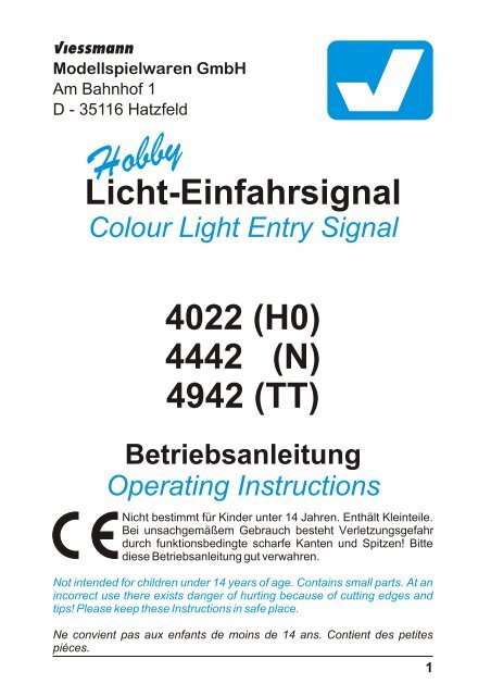
Hobby<br />
<strong>Licht</strong>-<strong>Einfahrsignal</strong><br />
Colour Light Entry Signal<br />
<strong>4022</strong> (<strong>H0</strong>)<br />
<strong>4442</strong> (N)<br />
<strong>4942</strong> (<strong>TT</strong>)<br />
Betriebsanleitung<br />
Operating Instructions<br />
Nicht bestimmt für Kinder unter 14 Jahren. Enthält Kleinteile.<br />
Bei unsachgemäßem Gebrauch besteht Verletzungsgefahr<br />
durch funktionsbedingte scharfe Kanten und Spitzen! Bitte<br />
diese Betriebsanleitung gut verwahren.<br />
Not intended for children under 14 years of age. Contains small parts. At an<br />
incorrect use there exists danger of hurting because of cutting edges and<br />
tips! Please keep these Instructions in safe place.<br />
Ne convient pas aux enfants de moins de 14 ans. Contient des petites<br />
piéces.<br />
1
Einleitung<br />
Introduction<br />
Die Hobby-<strong>Licht</strong>-<strong>Einfahrsignal</strong>e von Viessmann zeichnen sich durch ihr hervorragendes Preis-<br />
Leistungsverhältnis sowie durch einfache Montage und Anschlußmöglichkeit aus! Im am Signal<br />
angesetzten Antriebskasten befinden sich die elektronische Steuerung für die realistische<br />
Ansteuerung der einzelnen <strong>Licht</strong>signalbilder sowie die Relais für die Zugbeeinflussung. Dieses<br />
macht den Anschluß der Signale so einfach. Das Motto heißt “Auspacken, Anschließen und<br />
Losfahren”. Elektronische Vorkenntnisse sind nicht notwendig!<br />
The Hobby colour light entry signals from Viessmann convince by an excellent price-service relation<br />
and by an easy mounting and connecting! The foot box contains the electric control for a<br />
realistic controlling of the aspects as well as the relays for the train stop. For that reason the connection<br />
of the signals is so easy. The slogan is: unwrap, connect and go! There is no previous<br />
electronic know-how necessary.<br />
Aufstellung von <strong>Einfahrsignal</strong>en<br />
Putting-up of Entry Signals<br />
Sind in einem mehrgleisigen Bahnhof alle Gleise belegt, darf kein weiterer Zug in diesen Bahnhof<br />
einfahren, da es sonst zu Kollisionen kommen würde. Deshalb werden vor Bahnhöfen <strong>Einfahrsignal</strong>e<br />
plaziert, welche die Erlaubnis zum Einfahren geben. Diese stehen, wie die anderen<br />
Hauptsignale auch, in der Regel in Fahrtrichtung gesehen rechts vom Gleis. Ist das Gleis, in<br />
welches der Zug einfahren soll, frei und ausschließlich über die geraden Stränge der folgenden<br />
Weichen zu erreichen, zeigt das <strong>Einfahrsignal</strong> “Fahrt” an. Ist jedoch mindestens eine Weiche<br />
auf Abzweig gestellt, wird am <strong>Einfahrsignal</strong> “Langsamfahrt” signalisiert. Das bedeutet, es<br />
gilt für den sich anschließenden Weichenbereich eine Geschwindigkeitsbegrenzung auf in der<br />
Regel 40 km/h. Da nicht davon ausgegangen werden kann, daß eine Strecke nur in eine Richtung<br />
befahren wird, sind an beiden Enden des Bahnhofs <strong>Einfahrsignal</strong>e anzubringen. Soll aus<br />
dem Bahnhof heraus rangiert werden, so sind die <strong>Einfahrsignal</strong>e mindestens eine Rangierlänge<br />
vor den Bahnhof zu setzen. Damit die Rangiertafel nicht unmittelbar am <strong>Einfahrsignal</strong> steht,<br />
sollte das <strong>Einfahrsignal</strong> eine Rangierlänge plus die Länge einer großen Lok vor dem Bahnhof<br />
stehen (siehe Abbildung 1a). Ist ein Rangieren nicht notwendig, reicht es aus, wenn das <strong>Einfahrsignal</strong><br />
eine Loklänge vor der Weichengruppe steht (siehe Abbildung 1b).<br />
If all tracks of a station are occupied, there is no further train allowed to enter the station. For<br />
that, entry signals, which allow the engine driver to enter or tell him to stop, are placed in front of<br />
the station. These are placed - like the other main signals - at the right side of the tracks. If all<br />
turnouts in the following way are in the streight position and the way is free, then the entry signal<br />
shows “go”. If at least one of the followig turnouts is swiched to turn off, the signal shows “go<br />
slowly”. Then the maximum allowed speed for the following section is only 40 km/h. Because<br />
the tracks are used in both directions, entry signals have to be placed in front of both ends of the<br />
station. If it has to be shunt out of the station, the entry signal have to placed at least one shuntlength<br />
in front of the station. So that the shunt-board has not to be placed direct in front of the<br />
entry signal, the entry signal has to be placed one shunt-lengths plus the lengths of a large<br />
locomotive in front of the station (see figure 1a). If shunting is not needed, the entry signal could<br />
be placed one locomitive length in front of the first turnout (see figure 1b).<br />
Abbildung 1a<br />
Figure 1b<br />
2<br />
Rangierlänge<br />
shunt length<br />
mindestens eine<br />
Loklänge<br />
at least one<br />
locomotive length
A<br />
Bezeichnungsschild<br />
Number board<br />
A<br />
Abbildung 1b<br />
Figure 1b<br />
mindestens eine<br />
Loklänge<br />
at least one<br />
locomotive length<br />
Bezeichnung von <strong>Einfahrsignal</strong>en<br />
Nomenclature for Entry Signals<br />
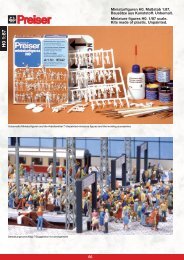
Dem Signal ist eine Tafel mit selbstklebenden Bezeichnungsschildern beigelegt. Schneiden<br />
Sie das gewünschte Bezeichnungsschild aus und kleben Sie es nach Abziehen der Schutzfolie<br />
auf die Nummerntafel des Signals. Hier einige Richtlinien zur korrekten Beschriftung von <strong>Einfahrsignal</strong>en:<br />
- <strong>Einfahrsignal</strong>e, die in Richtung der Kilometrierung der Strecke stehen, werden mit den Buchstaben<br />
A bis E beschriftet (diese Richtung wird als “Zählrichtung“ bezeichnet).<br />
- Die <strong>Einfahrsignal</strong>e der Gegenrichtung werden mit F bis K bezeichnet.<br />
- Gibt es nur ein Einfahrgleis je Richtung in Ihrem Bahnhof, so tragen die zugehörigen Signale<br />
die Buchstaben A und F.<br />
- Werden mehrere Gleise benutzt, fahren Sie in der Nomenklatur fort (bei z.B. drei Gleisen aus<br />
der Zählrichtung und zwei aus der Gegenrichtung lauten die Bezeichnungen A, B, C und F,<br />
G).<br />
The signal encloses a slab with self-pasting nomenclature pictures. Cut one of them out and<br />
paste it at the number board. Here are some guidelines for the correct inscription of the entry<br />
signals:<br />
- Entry signals, which stand in the direction of the line-kilometer are labeled by the letters A to E.<br />
This direction is called “counting direction”.<br />
- The entry signals of the other direction are labeled by the letters F - K.<br />
- If there is only one entry track for each direction at the station, the signals are labeled by the<br />
letters A and F.<br />
- If severals tracks are used, go on with the nomenclature. For example with three tracks in<br />
counting direction and two in the other, the signals are labeled A, B, C and F, G.<br />
Beispiel:<br />
Example<br />
0,0 km 1,0 km 2,0 km 3,0 km 4,0 km 5,0 km 6,0 km 7,0 km 8,0 km<br />
Funktionskontrolle<br />
Functional Test<br />
A<br />
Bahnhof<br />
Station<br />
Vor der Montage ist eine Funktionskontrolle durchzuführen. Zum Testen des <strong>Einfahrsignal</strong>s<br />
sind das gelbe und das braune Kabel vom Signal an je einem Pol eines 14 - 16 V-Modellbahntransformators<br />
(AC/DC) - z.B. Viessmann 5200 - anzuschließen. Beim kurzzeitigen (abwechselnden!)<br />
Anschluß der blauen Kabel an den Pol des Trafos, an dem sich das braune Signalanschlußkabel<br />
befindet, ergeben sich folgende Funktionen:<br />
F<br />
3
Before mounting you have to make a functional test.To test the entry signal you have to connect<br />
the yellow and the brown wire, each to one pole of a 14-16 V model train transformer (AC/DC) -<br />
for example Viessmann 5200. By alternating connection of the blue wires to the pole of the<br />
model train transformer where the brown wire has been connected to, you get the following<br />
functions:<br />
Kabelfarbensystem<br />
Wire colour system<br />
Anschluß<br />
Connection<br />
4<br />
Blau mit roter Markierung<br />
blue with a red mark<br />
Hp0 (Zughalt)<br />
Hp0 (stop)<br />
Blau mit grüner Markierung<br />
blue with a green mark<br />
Hp1 (Fahrt)<br />
Hp1 (go)<br />
Blau mit gelber Markierung<br />
blue with a yellow mark<br />
Hp2 (Langsamfahrt)<br />
Hp2 (go slowly)<br />
Signal auf Hp0 (“Zughalt”)<br />
Train stop (red)<br />
Signal auf Hp1 (“Fahrt”)<br />
Train go (green)<br />
Signal auf Hp2 (“Langsamfahrt”)<br />
Train go slowly (green-yellow)<br />
Betriebsspannung “Phase”<br />
Power supply<br />
Betriebsspannung “Masse”<br />
Power supply “ground”<br />
Zugbeeinflussungskontakt<br />
Train stop contact<br />
Zugbeeinflussungskontakt<br />
Train stop contact<br />
Vorsignalsteuerung<br />
Distant signal control<br />
Vorsignalsteuerung<br />
Distant signal control<br />
Die Stromquellen müssen so abgesichert sein, daß es im Falle eines Kurzschlusses<br />
nicht zum Kabelbrand kommen kann. Verwenden Sie nur<br />
handelsübliche und nach VDE/EN gefertigte Modellbahntransformatoren!<br />
The power sources must be protected to prevent the risk of burning wires. Only use VDE/EN<br />
tested special model train transformers for the power supply!<br />
Der konventionelle Anschluß der <strong>Einfahrsignal</strong>e ist in Abbildung 2 dargestellt. Die Stromversorgung<br />
erfolgt über das braune und gelbe Anschlußkabel. Die mit farbigen Markierungen versehenen<br />
blauen Kabel werden über Schaltkontakte (Einzeltaster, Gleiskontakte, Schaltgleise<br />
oder Tastenstellpulte) gegen das braune Anschlußkabel geschaltet. Hiermit kann zwischen<br />
den Signalbildern “Halt”, “Fahrt” oder “Langsamfahrt” umgeschaltet werden. Die beiden roten<br />
Anschlußkabel des Hobby-Signals schalten bei dem Signalbild Hp0 (”Halt”) den Strom im isolierten<br />
Halteabschnitt ab..
The correct conventional connection of an entry signal is shown in figure 2. The power supply<br />
occurs by the brown and the yellow wire. The blue wires with the coloured marks are switched<br />
by contacts (single keys, reed-contacts, switching rails or push button panels) to the brown<br />
wire. Depending on the position of the key you can see the signal aspect “stop”, “go” or “go<br />
slowly”. The two red wires of the Hobby-signal switch the power at the insulated stop track off, if<br />
the signal displays “stop”.<br />
Das rechte<br />
Schienenprofil<br />
entspricht bei<br />
Märklin dem<br />
Mittelleiter!<br />
The right rail<br />
corresponds with<br />
the third rail of<br />
Märklin!<br />
ca. 2<br />
Loklängen<br />
approx. 2<br />
locomotive<br />
lengths<br />
<strong>4022</strong><br />
<strong>4442</strong><br />
<strong>4942</strong><br />
Dieses Symbol kennzeichnet einen Schaltkontakt,<br />
z.B. einen Reed- (Magnet-) Schalter, Schaltgleis,<br />
Einzeltaster oder Tastenstellpult.<br />
This sign is used for a momentary switching contact<br />
like a reed contact, a switching track, a single momentary<br />
switch or a push button panel.<br />
In den Anschlußplänen dieser Anleitung finden Sie<br />
häufig das obenstehende Symbol. Es kennzeichnet<br />
eine Leitungsverbindung. Die sich hier kreuzenden<br />
Leitungen müssen an einer beliebigen Stelle ihres<br />
Verlaufs elektrisch leitend miteinander in Verbindung<br />
stehen. Der Verbindungspunkt muß also nicht<br />
exakt an der eingezeichneten Stelle sitzen, sondern<br />
kann z.B. zu einem Stecker, welcher sich an einer<br />
der kreuzenden Leitungen befindet, verlagert werden.<br />
Hp0<br />
Hp1<br />
Hp2<br />
Achtung!<br />
Weitere Anschlußbeispiele<br />
Further Connection Examples<br />
Sekundär<br />
16 V ~<br />
Gefertigt nach<br />
VDE 0551<br />
EN 60742<br />
Abbildung 2<br />
Figure 2<br />
Primär 230 V 50/60 Hz<br />
Sekundär 52 VA max. 3,25 A<br />
IP 40 ta 25°C<br />
Nur für trockene Räume<br />
<strong>Licht</strong>transformator 5200<br />
Alle Anschlußarbeiten sind nur bei abgeschalteter<br />
Betriebsspannung durchzuführen!<br />
Make sure that the power supply is switched off when<br />
you connect the wires!<br />
Primär<br />
230 V ~<br />
Attention!<br />
Fahrstrom<br />
konventionell oder digital<br />
Track Power<br />
analog or digital<br />
Dieses Symbol neben dem Gleis kennzeichnet eine<br />
in Fahrtrichtung rechtsseitige Trennstelle (z.B. mit<br />
Isolierschienenverbindern). Bei Märklin-Gleisen entspricht<br />
dieses einer Mittelleiter-Trennstelle.<br />
This sign beside the track indicates a track insulation<br />
on the right rail (if you look in driving direction). If you<br />
use the Märklin system this must be a third rail insulation.<br />
In the connection diagrams of this instruction you<br />
can often see the above shown symbol. It describes<br />
a wire connection. The wires which here are crossing<br />
themselves have to be connected electrically at<br />
any point on their way. So the connection point don’t<br />
need to be exactly at the shown location. It can be<br />
moved e.g. to a plug which is connected to one of the<br />
crossing wires.<br />
In den nachfolgenden Beispielen werden Ihnen einige weitere Möglichkeiten zum Anschluß<br />
der Hobby-Signale vorgestellt. Diese sollen Ihnen Anregungen zur Gestaltung Ihrer Modellbahnanlage<br />
geben.<br />
The following examples will show you some more possibilities to connect the Hobby-signals.<br />
These will help you by designing you model railway layout.<br />
5
<strong>Einfahrsignal</strong> mit Weiche gekoppelt<br />
Entry Signal coupled with a Turnout<br />
Das Hobby-<strong>Einfahrsignal</strong> kann auch in Kombination mit einer Weiche geschaltet werden. Wird<br />
die Weiche auf “Abzweig” gestellt, so wird das Signal gleichzeitig auf Hp2 (”Langsamfahrt”)<br />
geschaltet. Bei Geradeausfahrt wird das Signal entsprechend auf Hp1 (”Fahrt”) gestellt. Über<br />
die Gleiskontakte wird das Signal zurück auf Hp0 (”Halt”) geschaltet.<br />
The Hobby entry signal can be combined with a slow driving resistor (see figure 3). This occurs by<br />
the yellow marked red wires.The wiring works by separated tracks.<br />
ca. zwei<br />
Loklängen<br />
approx. two<br />
locomotive<br />
lengths<br />
6<br />
Abzweig<br />
Geradeaus<br />
<strong>4022</strong><br />
<strong>4442</strong><br />
<strong>4942</strong><br />
Abzweig<br />
Geradeaus<br />
Sekundär<br />
16 V ~<br />
Gefertigt nach<br />
VDE 0551<br />
EN 60742<br />
Primär 230 V 50/60 Hz<br />
Sekundär 52 VA max. 3,25 A<br />
IP 40 ta 25°C<br />
Nur für trockene Räume<br />
<strong>Licht</strong>transformator 5200<br />
Abbildung 3<br />
Figure 3<br />
Dieses Symbol kennzeichnet einen zugbetätigten<br />
Schaltkontakt, z.B. einen Reed- (Magnet-) Kontakt<br />
(Viessmann 6840) oder ein Schaltgleis.<br />
This sign is used for a train controlled momentary<br />
switching contact like a reed (magnetic) contact<br />
(Viessmann 6840) or a switching track.<br />
Primär<br />
230 V ~<br />
Fahrstrom<br />
konventionell oder digital<br />
Track Power<br />
analog or digital<br />
Das rechte<br />
Schienenprofil entspricht bei Märklin dem Mittelleiter!<br />
The right rail corresponds with the third rail of Märklin!
<strong>Einfahrsignal</strong> und Vorsignal<br />
Distant Signal and Entry Signal<br />
Ein Vorsignal macht den Lokomotivführer bereits eine Weile vorher auf das Signalbild aufmerksam,<br />
welches ihn am nächsten im Fahrweg liegenden Hauptsignal erwartet. Das Vorsignal eines<br />
<strong>Einfahrsignal</strong>s zeigt also entweder “Fahrt erwarten” (Vr1 = zwei grüne <strong>Licht</strong>er), “Halt erwarten”<br />
(Vr0 = zwei gelbe <strong>Licht</strong>er) oder “Langsamfahrt erwarten” (Vr2 = ein grünes und ein gelbes<br />
<strong>Licht</strong>) an. Beim Vorbild stehen Vorsignale entweder 400 m, 700 m oder 1000 m vor dem<br />
Hauptsignal, je nach zulässiger Höchstgeschwindigkeit auf der Strecke.<br />
Auch das Hobby-<strong>Einfahrsignal</strong> kann in Kombination mit einem Hobby-Vorsignal angeordnet werden<br />
(siehe Abbildung 4). Dazu werden beide Signale mit Hilfe der mit einer grünen und gelben<br />
Markierung versehenen lilafarbenen Kabel miteinander verbunden. Die Stromversorgung des<br />
Vorsignals erfolgt über dessen braunes und gelbes Anschlußkabel. So kündigt das Vorsignal<br />
immer das Signalbild des <strong>Einfahrsignal</strong>s an.<br />
Das rechte<br />
Schienenprofil<br />
entspricht bei<br />
Märklin dem<br />
Mittelleiter!<br />
The right rail<br />
corresponds with<br />
the third rail of<br />
Märklin!<br />
ca. zwei<br />
Loklängen<br />
approx. two<br />
locomotive<br />
lengths<br />
ca. eine<br />
maximale<br />
Zuglänge<br />
approx. one<br />
maximum<br />
train length<br />
Abbildung 4<br />
Figure 4<br />
<strong>4022</strong><br />
<strong>4442</strong><br />
<strong>4942</strong><br />
4020<br />
4440<br />
4940<br />
Hp0<br />
Hp1<br />
Hp2<br />
A distant signal shows the engine<br />
driver the aspect of the next main<br />
signal in direction before he passes<br />
it. The distant signal either shows<br />
“expect stop” (Vr0 = two yellow<br />
lights), “expect go” (Vr1 = two green<br />
lights) or “expect go slowly” (Vr2 =<br />
one green and one yellow light). In<br />
reality, the distant signals are<br />
placed 400 m, 700 m or 1000 m in<br />
front of the main signal, depending<br />
on the allowed high-speed.<br />
The Hobby entry signal can also be<br />
combined with a Hobby distant signal<br />
(see figure 4). For that, both signals<br />
have to be connected by the green<br />
and yellow marked lilac wires. The<br />
electric power is con-ected to the<br />
distant signal by the brown and the<br />
yellow wire. So the distant signal<br />
shows always the same aspect as<br />
the main signal.<br />
Sekundär<br />
16 V ~<br />
Gefertigt nach<br />
VDE 0551<br />
EN 60742<br />
Primär 230 V 50/60 Hz<br />
Sekundär 52 VA max. 3,25 A<br />
IP 40 ta 25°C<br />
Nur für trockene Räume<br />
<strong>Licht</strong>transformator 5200<br />
Primär<br />
230 V ~<br />
Fahrstrom<br />
konventionell oder digital<br />
Track Power<br />
analog or digital<br />
7
Ansteuerung über Digitalsysteme<br />
Controlling by Digital Systems<br />
Die Hobby-Signale können auch mit einem Digitalsystem angesteuert werden (Abbildung 5).<br />
Beim Anschluß der Signale an einen Digital-Decoder wie z.B. Viessmann 5211 (für Märklin-Digital<br />
bzw. das Motorola-Format) oder Viessmann 5212 für das NMRA (DCC)-Format ist darauf<br />
zu achten, daß die braune Signal-Masseleitung, welche am Versorgungstrafo der Hobby-Signale<br />
angeschlossen ist, auch mit der Digitalmasse verbunden ist. Der Decoder muß positive<br />
Schaltimpulse liefern! Dieses ist bei dem Decoder des Märklin-Digitalsystems (k83) sowie allen<br />
Viessmann-Decodern<br />
der Fall. Da das <strong>Einfahrsignal</strong> drei Begriffe darstellen kann, müssen<br />
auch drei Einzelausgänge des Digitaldecoders verwendet werden.<br />
Hobby signals can also be controlled by digital systems (see figure 5). If connecting the signals to<br />
digital decoders like Viessmann 5211 (for Märklin-Digital or the Motorola format) or the Viessmann<br />
5212 for the NMRA (DCC)-Format, it is necessary to connect the brown signal wire<br />
(ground), which is connected to the transformer, to the digital ground. The decoder has to send<br />
positive switching pulses. This is ensured by the Märklin digital decoder (k83) and all decoders<br />
made by Viessmann. Because the entry signal is able to display three different aspects, you<br />
have to use three single outputs of your decoder to control the entry signal.<br />
Das rechte<br />
Schienenprofil<br />
entspricht bei<br />
Märklin dem<br />
Mittelleiter!<br />
The right rail<br />
corresponds with<br />
the third rail of<br />
Märklin!<br />
ca. 2<br />
Loklängen<br />
approx. 2<br />
locomotive<br />
lengths<br />
Technische Daten<br />
Technical Data<br />
8<br />
1 2 3 4 5 6 7 8<br />
Adresse<br />
E<br />
ON WnP<br />
4<br />
Weichendecoder 5211<br />
1<br />
<strong>4022</strong><br />
<strong>4442</strong><br />
<strong>4942</strong><br />
Hp0<br />
3<br />
2<br />
Hp1<br />
Widerstand<br />
1,5 kOhm<br />
Resistor<br />
1,5 kOhm<br />
Hp2<br />
Digitaldecoder mit<br />
positiven Schaltimpulsen<br />
Digital decoder with<br />
positive switching pulses<br />
Diese Kabel dienen der<br />
Steuerung eines Vorsignals!<br />
These wires are intended for<br />
controlling a distant signal<br />
Sekundär<br />
16 V ~<br />
Gefertigt nach<br />
VDE 0551<br />
EN 60742<br />
Primär 230 V 50/60 Hz<br />
Sekundär 52 VA max. 3,25 A<br />
IP 40 ta 25°C<br />
Nur für trockene Räume<br />
<strong>Licht</strong>transformator 5200<br />
Masseverbindung zwischen<br />
Signal und Digitalsystem!<br />
Ground connection between<br />
signal and digital system!<br />
Abbildung 5<br />
Figure 5<br />
Primär<br />
230 V ~<br />
Fahrstrom digital<br />
Track Power digital<br />
Betriebsspannung Operating voltage<br />
14 - 16 V AC/DC<br />
Kontaktbelastbarkeit (der beiden roten Kabel) 2 A<br />
Max. contact load (the two red wires) 2 A<br />
Maße des Antriebskastens (Länge x Breite x Höhe) 43 x 16 x 10,5 mm<br />
Size of the relay box (length x width x height) 43 x 16 x 10,5 mm<br />
Sachnummer 98xxx