Magnetartikeldecoder 5212 Betriebsanleitung DCC Digital Decoder ...
Magnetartikeldecoder 5212 Betriebsanleitung DCC Digital Decoder ...
Magnetartikeldecoder 5212 Betriebsanleitung DCC Digital Decoder ...

Erfolgreiche ePaper selbst erstellen
Machen Sie aus Ihren PDF Publikationen ein blätterbares Flipbook mit unserer einzigartigen Google optimierten e-Paper Software.
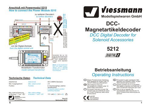
Anschluß mit Powermodul 5215<br />
How to connect the Power Module 5215<br />
von der <strong>Digital</strong>-Zentrale<br />
from the digital central unit<br />
Technische Daten<br />
Technical Data<br />
Datenformat Data format<br />
<strong>DCC</strong> (NMRA-Standard)<br />
Max. Ausgangsstrom Max. output current 2 A<br />
Funktion Function<br />
8 Impulsausgänge, positive<br />
Schaltimpulse<br />
8 impulse outputs, positive<br />
switching impulses<br />
Max. externe Spannung Max. extern voltage<br />
an Buchsen “~” und “ ~(E)” at sockets “~” and “~ (E)” 17V ~(eff) AC / 24 V = DC<br />
6<br />
braun brown<br />
~ ~ ( E)<br />
Adresse<br />
J K<br />
rot red<br />
4 3<br />
Viessmann<br />
Modellspielwaren GmbH<br />
Am Bahnhof 1<br />
D - 35116 Hatzfeld<br />
www.viessmann-modell.de<br />
viessmann<br />
<strong>DCC</strong> - 5 212<br />
<strong>Magnetartikeldecoder</strong><br />
1 2<br />
<strong>DCC</strong> (NMRA)-System<br />
<strong>DCC</strong> (NMRA) system<br />
Primär<br />
230 V ~<br />
zu weiteren <strong>Decoder</strong>n<br />
to further decoders<br />
E<br />
Viessmann<br />
Lichttransformator 5200<br />
Primär 230 V 50/60 Hz<br />
Sekundär 52 VA max. 3,25 A<br />
IP 40 ta 25°C<br />
Nur für trockene Räume<br />
Gefertigt nach<br />
VDE 0551<br />
EN 60742<br />
E<br />
Sekundär<br />
16 V ~<br />
zu den <strong>Decoder</strong>n<br />
Powermodul 5215<br />
Braune Massebuchsen nicht koppeln!<br />
max. 24V ~<br />
gelb<br />
yellow<br />
Modellbahn-Transformator<br />
model railroad transformer<br />
braun<br />
brown<br />
Never connect the both<br />
brown sockets of the<br />
Power Module !<br />
Die beiden braunen Buchsen des<br />
Powermoduls dürfen niemals miteinander<br />
verbunden werden!<br />
Verwenden Sie zur Versorgung<br />
des Powermoduls<br />
nicht den Versorgungstrafo<br />
Ihres <strong>Digital</strong>systems,<br />
sondern einen separaten<br />
Trafo!!<br />
Never use the transformer<br />
from your digital system.<br />
Always use a separate<br />
transformer to supply the<br />
Power Module!<br />
Stand 02<br />
Sachnummer 98777<br />
Viessmann<br />
Modellspielwaren GmbH<br />
<strong>DCC</strong>-<br />
<strong>Magnetartikeldecoder</strong><br />
<strong>DCC</strong> <strong>Digital</strong> <strong>Decoder</strong> for<br />
Solenoid Accessories<br />
<strong>5212</strong><br />
<strong>Betriebsanleitung</strong><br />
Operating Instructions<br />
D Dieses Produkt ist kein Spielzeug.<br />
Nicht geeignet für Kinder unter 14<br />
Jahren! Anleitung aufbewahren!<br />
GB This product is not a toy.<br />
Not suitable for children under 14<br />
years! Keep instructions!<br />
F Ce produit n'est pas un jouet. Ne<br />
convient pas aux enfants de moins<br />
de 14 ans! Conservez cette notice<br />
d’instructions!<br />
gemäß<br />
EG-Richtlinie<br />
89/336/EWG<br />
NL Dit produkt is geen speelgoed. Niet<br />
geschikt voor kinderen onder 14 jaar!<br />
Gebruiksaanwijzing bewaren!<br />
I Questo prodotto non è un giocattolo.<br />
Non adatto a bambini al di sotto dei 14<br />
anni! Conservare instruzioni per l’uso!<br />
E Esto no es un juguete. No<br />
recomendado para menores de 14<br />
años! Conserva las instrucciones de<br />
servicio!<br />
1
Der <strong>DCC</strong>-<strong>Magnetartikeldecoder</strong> <strong>5212</strong> von viessmann besitzt 8 separat ansteuerbare, kurzschlußsichere<br />
Impulsausgänge, welche zum Schalten von z.B. Formsignalen, Entkupplungsgleisen<br />
oder Weichen eingesetzt werden können.<br />
Der <strong>Magnetartikeldecoder</strong> <strong>5212</strong> versteht sowohl das <strong>DCC</strong>(NMRA)- als auch das Märklin-Motorola-Datenformat<br />
und kann somit vom Märklin <strong>Digital</strong>~ - System, dem alten Märklin <strong>Digital</strong>= -<br />
System, Arnold digital neu und alt (jeweils mit dem Keyboard, Switchboard oder auch dem<br />
Interface), Lenz DIGITAL plus, Digitrax, der Intellibox von Uhlenbrock sowie allen anderen<br />
<strong>DCC</strong>- und Märklin-Motorola-kompatiblen <strong>Digital</strong>systemen angesteuert werden .<br />
Hierzu muß der <strong>Decoder</strong> auf eine Adresse eingestellt werden, welche ihn 4 aufeinanderfolgenden<br />
Tastenpaaren eines Switch- oder Keyboards oder der Intellibox zuordnet, siehe Abschnitt<br />
“Adreßeinstellung” ab Seite 3.<br />
Wichtig! Die Buchsen<br />
“~” immer anschließen!<br />
Important! The “~”sockets<br />
always have to<br />
be connected!<br />
von der<br />
Zentraleinheit<br />
bzw. vom Gleis<br />
from the central<br />
unit resp. from the<br />
rail<br />
Je zwei Impulsausgänge sind zu einem Ausgangspaar (rot/grün) zusammengefaßt. Die Ausgangspaare<br />
1 bis 4 werden über je ein Tastenpaar des Keyboards angesteuert. Ein Druck auf<br />
eine grüne Taste erzeugt einen Spannungsimpuls an der jeweiligen grünen Buchse des <strong>Magnetartikeldecoder</strong>s,<br />
ein Druck auf die rote Taste hingegen an der entsprechenden roten Buchse.<br />
Die jeweilige mittlere (gelbe) Buchse ist der gemeinsame Rückleiter.<br />
Als Besonderheit des viessmann-<strong>Magnetartikeldecoder</strong>s wird die Schaltspannung über die<br />
Zusatzbuchsen "~" separat in den <strong>Decoder</strong> eingespeist. Diese kann nun wahlweise vom <strong>Digital</strong>stromkreis<br />
abgezweigt (Abbildung 1) oder einem separaten Transformator entnommen<br />
werden (Abbildung 2). Die letztere Möglichkeit entlastet Ihren Booster und gewährleistet, daß<br />
die Weichen und Signale auch bei vielen gleichzeitig fahrenden Zügen noch sicher schalten.<br />
Zur Erzielung der optimalen Schaltleistung ist es jedoch empfehlenswert, als separate Spannungsquelle<br />
eine Gleichspannung zu nehmen bzw. die Versorgung der “E”-Buchse über das<br />
Powermodul 5215 vorzunehmen (siehe Seite 6). Die Polarität ist der Abbildung 2 zu entnehmen<br />
(”~” = "+" = braun, “ ~ ( E)” = "-" = rot, das ist kein Druckfehler!).<br />
2<br />
rot red<br />
schwarz black<br />
~ ~ ( E)<br />
Achtung!<br />
Bei separater Schaltspannungseinspeisung (nach Abbildung 2) die Leitungen zur<br />
Spannungsversorgung und die Kabel des <strong>Digital</strong>stromkreises nicht zusammenschalten!<br />
Allerdings müssen die Buchsen "~" immer entweder nach Abbildung 1 oder Abbildung<br />
2 angeschlossen sein, da ansonsten vom <strong>Decoder</strong> keine Spannungsimpulse<br />
an dessen Ausgängen erzeugt werden können.<br />
Adresse<br />
4 3<br />
viessmann<br />
<strong>DCC</strong> -<br />
<strong>5212</strong><br />
<strong>Magnetartikeldecoder</strong><br />
J K<br />
1<br />
2<br />
grün green<br />
weiß white<br />
gelb yellow<br />
1<br />
Weiche<br />
Turnout<br />
How to set the Address<br />
You can set the address with the red button named “Adresse” on the top of the decoder housing.<br />
At first you have to connect the decoder to your digital system like it is shown in figure 1 on<br />
page 2. It also would help you to connect a turnout to output 1 like it is shown in the same figure<br />
(in this example the wire colours from Trix are used).To set a <strong>DCC</strong> address, you have to push<br />
the red “Adresse”-button one time. The turnout which you have connected to output 1 toggles<br />
slowly a few times. Now you can send an address by your <strong>DCC</strong> digital system, on which the decoder<br />
shall react (as if you want to swich a magnetic article). You can set the decoder only to a<br />
group of 4 succeeding addresses, for example 1 - 4, 5 - 8, 9 - 12. So it is not possible to set the<br />
decoder to the addresses 3 - 6, because they don’t belong to the same group . Which key you<br />
will press within the group is fully unimportant. Of course you can also send a switching command<br />
by a railroad control software from your computer (e.g. Viessmann 1011 WIN-DIGIPET).<br />
If the decoder has accepted the address, the turnout which you have connected to output 1<br />
toggles again slowly a few times. Then the programming of a <strong>DCC</strong> address is finished.<br />
If you push the red “Adresse” button a second time instead of sending a <strong>DCC</strong> command, the<br />
turnout toggles fast a few times. Now you can store a Motorola (Märklin digital~) address to the<br />
<strong>5212</strong> decoder. For this of course you must connect the decoder to a digital system which is<br />
compatible to the Motorola format (e.g. Märklin digital~) and send a Motorola command. A<br />
successfull programming also in this case will be confirmed by the turnout at output 1 - it toggles<br />
slowly a few times.<br />
With a third push on the red decoder button you can leave the address programming mode<br />
without any changes.<br />
Wichtiger Hinweis für Minitrix-Anwender!<br />
Important Hint for Minitrix Users!<br />
Bei Verwendung von Weichenantrieben der Marke<br />
Minitrix kann es zu Problemen kommen. Diese haben<br />
im Schaltmoment eine Stromaufnahme von 2,2<br />
Ampere! Hier spricht natürlich die Überlastsicherung<br />
des <strong>5212</strong> an, um die Endstufen vor dem Überhitzungstod<br />
zu bewahren.<br />
Die Lösung des Problems: Zunächst schließen<br />
Sie die "E"-Buchse jedes <strong>Decoder</strong>s an einem Viessmann-Powermodul<br />
5215 an (es reicht wohlgemerkt<br />
ein Powermodul für alle angeschlossenen <strong>Decoder</strong><br />
<strong>5212</strong> aus). Dieses Powermodul versorgen Sie mit<br />
16 Volt Wechselspannung, wie sie vom Viessmann-<br />
Lichttransformator 5200 geliefert wird.<br />
Nun das Wichtigste: In die weiße Zuleitung (gemeinsamer<br />
Pol beider Antriebsspulen) jeder Minitrixweiche,<br />
welche ja am gelben (mittleren) Pol der<br />
Ausgangsbuchsen-Dreiergruppen des <strong>Magnetartikeldecoder</strong>s<br />
<strong>5212</strong> angeschlossen wird, schalten<br />
Sie einen Widerstand von 5,6 Ohm und einer Leistung<br />
von 1 W.<br />
Achtung!<br />
Attention!<br />
grün green<br />
5,6 Ohm<br />
1 Watt<br />
gelb yellow<br />
Minitrix-Weiche Minitrix-Turnout<br />
If you want to switch a Minitrix turnout you will get a<br />
problem because normally it needs about 2,2 A in<br />
the switching moment. Then of course the overload<br />
protection unit of the <strong>5212</strong> disables the output.<br />
The solution of the problem: At first you have to<br />
connect the “E”-socket of every decoder to one<br />
Viessmann-Powermodul 5215 (one Powermodul is<br />
enough for all your decoders). This Powermodul<br />
you have to connect to a 16 V AC model railroad<br />
transformer, e.g. the Viessmann-Lighttransformer<br />
5200. The most important thing: In the white common<br />
wire of every Minitrix turnout you have to put a<br />
5,6 Ohm/1 W resistor.<br />
Alle Anschlußarbeiten sind nur bei abgeschalteter Betriebsspannung<br />
durchzuführen!<br />
Make sure that the power supply is switched off when you connect the wires!<br />
Die Stromquellen müssen so abgesichert sein, daß es im Falle eines Kurzschlusses<br />
nicht zum Kabelbrand kommen kann. Verwenden Sie nur<br />
handelsübliche und nach VDE/EN gefertigte Modellbahntransformatoren!<br />
The power sources must be protected to prevent the risk of burning wires. Only use<br />
VDE/EN tested special model train transformers for the power supply!<br />
5
The decoder viessmann <strong>5212</strong> has got eight separately switchable, short circuit proof impulse<br />
outputs which can be used for example to switch semaphores, turnouts or uncoupling tracks.<br />
The decoder understands the <strong>DCC</strong> and the Motorola data format and so it can be used with the<br />
system Märklin <strong>Digital</strong>~, the old Märklin <strong>Digital</strong>=, Arnold digital new and old (controllable by the<br />
Interface, the Keyboard or the Switchboard), Lenz DIGITAL plus, Digitrax, the Uhlenbrock Intellibox<br />
and all other <strong>DCC</strong>- and Märklin-Motorola-compatible digital systems.<br />
The <strong>5212</strong> has to be set to an address, which classes it with 4 succeeding pairs of switches of a<br />
Switchboard, a Keyboard or the Intellibox. This is described in chapter “How to set the address”.<br />
Wichtig! Die Buchsen<br />
“~” immer anschließen!<br />
Important! The “~”sockets<br />
always have to<br />
be connected!<br />
~ ~ ( E)<br />
rot red<br />
E<br />
von der<br />
Zentraleinheit<br />
bzw. vom Gleis<br />
zum Trafo<br />
to a transformer<br />
()16 + V _~<br />
(-) AC/DC<br />
from the central<br />
unit resp. from<br />
the rail<br />
schwarz black<br />
Always two impulse outputs are combined to a pair (red/green). The output pairs 1 to 4 are each<br />
controlled by a push button pair of the Keyboard. A push on the green button will case an impulse<br />
at the corresponding green socket of the decoder, a push on the red button generates an<br />
impulse at the red output. The yellow socket is the common pole.<br />
A special feature of the viessmann-decoder is the possibility to supply the switching power separately<br />
at the extra sockets "~”. You have the choice to use either the digital current (see<br />
picture 1) or the current from an extra transformer (see picture 2).The second possibility relieves<br />
your digital booster and assures a reliable switching of the turnouts and semaphores,<br />
even if a lot of trains are driving simultaneously.<br />
To get the optimum of switching power you should use a DC transformer or the Viessmann<br />
Power Module 5215 for the extern power supply. This is shown on page 6. Then you must take<br />
care of the polarity (”~” = "+" = brown, “~ (E)” = "-" = red, that’s no printing error! ).<br />
Attention!<br />
If you use a separate transformer (like in picture 2) don't connect the wires “~” for the<br />
power supply to the wires of the digital current circuit.<br />
Adresse<br />
E<br />
4 3<br />
viessmann<br />
<strong>DCC</strong> -<br />
<strong>5212</strong><br />
<strong>Magnetartikeldecoder</strong><br />
J K<br />
1<br />
2<br />
But the sockets “~” always must be connected like it is shown in picture 1 and 2. If<br />
you don't do this, the decoder isn't able to generate the power impulses at its<br />
outputs.<br />
Adreßeinstellung<br />
rot red<br />
braun braun<br />
Die Adreßeinstellung erfolgt über den mit “Adresse” bezeichneten roten Drucktaster am <strong>Magnetartikeldecoder</strong>.<br />
Dazu wird der <strong>Decoder</strong> zunächst gemäß Abbildung 1 am <strong>Digital</strong>system angeschlossen.<br />
Hilfreich ist außerdem eine am Ausgang 1 angeschlossene Weiche, wie es in Abbildung<br />
1 anhand einer Trix-Weiche (Kabelfarben) exemplarisch dargestellt ist. Um nun eine<br />
<strong>DCC</strong>-Adresse zu programmieren, drücken Sie den roten Taster am <strong>Magnetartikeldecoder</strong> einmal.<br />
Die an Ausgang 1 angeschlossene Weiche schaltet langsam hin und her. Nun können Sie<br />
an Ihrem <strong>DCC</strong>-<strong>Digital</strong>system eine der Adressen senden, auf die der <strong>Decoder</strong> reagieren soll (als<br />
ob Sie einen Magnetartikel schalten wollten). Der <strong>Decoder</strong> läßt sich nur auf eine Gruppe von<br />
2<br />
3<br />
4 aufeinanderfolgenden Weichenadressen programmieren, z.B. 1 - 4, 5 - 8, 9 - 12. Es ist also<br />
nicht möglich, den <strong>Decoder</strong> auf die Adressen 3 - 6 zu programmieren, da diese Adressen 2 verschiedenen<br />
Gruppen angehören. Welche Taste innerhalb der Vierergruppe Sie bei der Programmierung<br />
drücken, ist völlig gleich. Alternativ können Sie auch einen Weichenschaltbefehl<br />
über ein Modellbahn-Steuerungsprogramm Ihres Computers (z.B. Viessmann 1011 WIN-DIGI-<br />
PET) auslösen.<br />
Hat der <strong>Decoder</strong> die Adresse akzeptiert, schaltet die an Ausgang 1 angeschlossene Weiche<br />
noch einmal langsam hin und her. Die Programmierung ist damit abgeschlossen.<br />
Drücken Sie, anstatt eine <strong>DCC</strong>-Adresse zu senden, ein zweites Mal auf den roten Taster des<br />
<strong>5212</strong>, so schaltet die an Ausgang 1 angeschlossene Weiche schnell hin und her. Nun können<br />
Sie den <strong>Decoder</strong> auf eine Motorola-Adresse programmieren. Hierzu muß der <strong>Decoder</strong><br />
natürlich an ein Motorola-kompatibles <strong>Digital</strong>system (z.B. Märklin <strong>Digital</strong> ~) angeschlossen<br />
sein und eine Motorola-Adresse ausgesendet werden. Eine erfolgreiche Programmierung wird<br />
auch hier durch ein langsames Hin- und Herschalten der angeschlossenen Weiche bestätigt.<br />
Mit einem dritten Druck auf den roten Taster des <strong>Decoder</strong>s verlassen Sie ohne Veränderung<br />
der Adresse den Adreß-Programmiermodus.<br />
Anschluß von viessmann-Formsignalen<br />
How to Connect viessmann Semaphores<br />
zum Trafo to a transformer<br />
16 V _~<br />
AC/DC<br />
4<br />
braun<br />
braun<br />
Adresse<br />
E<br />
~ ~ ( E)<br />
4 3<br />
viessmann<br />
<strong>DCC</strong> -<br />
<strong>5212</strong><br />
<strong>Magnetartikeldecoder</strong><br />
J K<br />
1<br />
2<br />
rot red<br />
braun brown<br />
rot<br />
red<br />
blau blue<br />
gelb yellow<br />
blau blue<br />
blau blue<br />
Mittelleiter - Trennstellen<br />
third rail insulations<br />
z.B. 4502<br />
und alle anderen viessmann-<br />
Formsignale mit zwei Antrieben<br />
e.g. 4502<br />
and all other viessmann sema-<br />
phores with<br />
two motors<br />
z.B. 4500<br />
und alle anderen<br />
Viessmann-Formsignale<br />
mit einem Antrieb<br />
16 V _~ (AC/DC)<br />
zum Lichttrafo<br />
to the light transformer<br />
1,5 kOhm<br />
1/4 Watt<br />
zum Gleis<br />
to the rail<br />
e.g. 4500<br />
and all other<br />
viessmann semaphores<br />
with only<br />
one motor<br />
16 V _~ (AC/DC)<br />
zum Lichttrafo<br />
to the light<br />
transformer<br />
1,5 kOhm<br />
1/4 Watt