Magnetartikeldecoder 5212 Betriebsanleitung DCC Digital Decoder ...
Magnetartikeldecoder 5212 Betriebsanleitung DCC Digital Decoder ...
Magnetartikeldecoder 5212 Betriebsanleitung DCC Digital Decoder ...

Erfolgreiche ePaper selbst erstellen
Machen Sie aus Ihren PDF Publikationen ein blätterbares Flipbook mit unserer einzigartigen Google optimierten e-Paper Software.
Der <strong>DCC</strong>-<strong>Magnetartikeldecoder</strong> <strong>5212</strong> von viessmann besitzt 8 separat ansteuerbare, kurzschlußsichere<br />
Impulsausgänge, welche zum Schalten von z.B. Formsignalen, Entkupplungsgleisen<br />
oder Weichen eingesetzt werden können.<br />
Der <strong>Magnetartikeldecoder</strong> <strong>5212</strong> versteht sowohl das <strong>DCC</strong>(NMRA)- als auch das Märklin-Motorola-Datenformat<br />
und kann somit vom Märklin <strong>Digital</strong>~ - System, dem alten Märklin <strong>Digital</strong>= -<br />
System, Arnold digital neu und alt (jeweils mit dem Keyboard, Switchboard oder auch dem<br />
Interface), Lenz DIGITAL plus, Digitrax, der Intellibox von Uhlenbrock sowie allen anderen<br />
<strong>DCC</strong>- und Märklin-Motorola-kompatiblen <strong>Digital</strong>systemen angesteuert werden .<br />
Hierzu muß der <strong>Decoder</strong> auf eine Adresse eingestellt werden, welche ihn 4 aufeinanderfolgenden<br />
Tastenpaaren eines Switch- oder Keyboards oder der Intellibox zuordnet, siehe Abschnitt<br />
“Adreßeinstellung” ab Seite 3.<br />
Wichtig! Die Buchsen<br />
“~” immer anschließen!<br />
Important! The “~”sockets<br />
always have to<br />
be connected!<br />
von der<br />
Zentraleinheit<br />
bzw. vom Gleis<br />
from the central<br />
unit resp. from the<br />
rail<br />
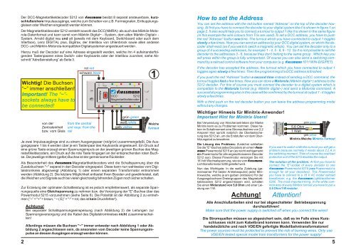
Je zwei Impulsausgänge sind zu einem Ausgangspaar (rot/grün) zusammengefaßt. Die Ausgangspaare<br />
1 bis 4 werden über je ein Tastenpaar des Keyboards angesteuert. Ein Druck auf<br />
eine grüne Taste erzeugt einen Spannungsimpuls an der jeweiligen grünen Buchse des <strong>Magnetartikeldecoder</strong>s,<br />
ein Druck auf die rote Taste hingegen an der entsprechenden roten Buchse.<br />
Die jeweilige mittlere (gelbe) Buchse ist der gemeinsame Rückleiter.<br />
Als Besonderheit des viessmann-<strong>Magnetartikeldecoder</strong>s wird die Schaltspannung über die<br />
Zusatzbuchsen "~" separat in den <strong>Decoder</strong> eingespeist. Diese kann nun wahlweise vom <strong>Digital</strong>stromkreis<br />
abgezweigt (Abbildung 1) oder einem separaten Transformator entnommen<br />
werden (Abbildung 2). Die letztere Möglichkeit entlastet Ihren Booster und gewährleistet, daß<br />
die Weichen und Signale auch bei vielen gleichzeitig fahrenden Zügen noch sicher schalten.<br />
Zur Erzielung der optimalen Schaltleistung ist es jedoch empfehlenswert, als separate Spannungsquelle<br />
eine Gleichspannung zu nehmen bzw. die Versorgung der “E”-Buchse über das<br />
Powermodul 5215 vorzunehmen (siehe Seite 6). Die Polarität ist der Abbildung 2 zu entnehmen<br />
(”~” = "+" = braun, “ ~ ( E)” = "-" = rot, das ist kein Druckfehler!).<br />
2<br />
rot red<br />
schwarz black<br />
~ ~ ( E)<br />
Achtung!<br />
Bei separater Schaltspannungseinspeisung (nach Abbildung 2) die Leitungen zur<br />
Spannungsversorgung und die Kabel des <strong>Digital</strong>stromkreises nicht zusammenschalten!<br />
Allerdings müssen die Buchsen "~" immer entweder nach Abbildung 1 oder Abbildung<br />
2 angeschlossen sein, da ansonsten vom <strong>Decoder</strong> keine Spannungsimpulse<br />
an dessen Ausgängen erzeugt werden können.<br />
Adresse<br />
4 3<br />
viessmann<br />
<strong>DCC</strong> -<br />
<strong>5212</strong><br />
<strong>Magnetartikeldecoder</strong><br />
J K<br />
1<br />
2<br />
grün green<br />
weiß white<br />
gelb yellow<br />
1<br />
Weiche<br />
Turnout<br />
How to set the Address<br />
You can set the address with the red button named “Adresse” on the top of the decoder housing.<br />
At first you have to connect the decoder to your digital system like it is shown in figure 1 on<br />
page 2. It also would help you to connect a turnout to output 1 like it is shown in the same figure<br />
(in this example the wire colours from Trix are used).To set a <strong>DCC</strong> address, you have to push<br />
the red “Adresse”-button one time. The turnout which you have connected to output 1 toggles<br />
slowly a few times. Now you can send an address by your <strong>DCC</strong> digital system, on which the decoder<br />
shall react (as if you want to swich a magnetic article). You can set the decoder only to a<br />
group of 4 succeeding addresses, for example 1 - 4, 5 - 8, 9 - 12. So it is not possible to set the<br />
decoder to the addresses 3 - 6, because they don’t belong to the same group . Which key you<br />
will press within the group is fully unimportant. Of course you can also send a switching command<br />
by a railroad control software from your computer (e.g. Viessmann 1011 WIN-DIGIPET).<br />
If the decoder has accepted the address, the turnout which you have connected to output 1<br />
toggles again slowly a few times. Then the programming of a <strong>DCC</strong> address is finished.<br />
If you push the red “Adresse” button a second time instead of sending a <strong>DCC</strong> command, the<br />
turnout toggles fast a few times. Now you can store a Motorola (Märklin digital~) address to the<br />
<strong>5212</strong> decoder. For this of course you must connect the decoder to a digital system which is<br />
compatible to the Motorola format (e.g. Märklin digital~) and send a Motorola command. A<br />
successfull programming also in this case will be confirmed by the turnout at output 1 - it toggles<br />
slowly a few times.<br />
With a third push on the red decoder button you can leave the address programming mode<br />
without any changes.<br />
Wichtiger Hinweis für Minitrix-Anwender!<br />
Important Hint for Minitrix Users!<br />
Bei Verwendung von Weichenantrieben der Marke<br />
Minitrix kann es zu Problemen kommen. Diese haben<br />
im Schaltmoment eine Stromaufnahme von 2,2<br />
Ampere! Hier spricht natürlich die Überlastsicherung<br />
des <strong>5212</strong> an, um die Endstufen vor dem Überhitzungstod<br />
zu bewahren.<br />
Die Lösung des Problems: Zunächst schließen<br />
Sie die "E"-Buchse jedes <strong>Decoder</strong>s an einem Viessmann-Powermodul<br />
5215 an (es reicht wohlgemerkt<br />
ein Powermodul für alle angeschlossenen <strong>Decoder</strong><br />
<strong>5212</strong> aus). Dieses Powermodul versorgen Sie mit<br />
16 Volt Wechselspannung, wie sie vom Viessmann-<br />
Lichttransformator 5200 geliefert wird.<br />
Nun das Wichtigste: In die weiße Zuleitung (gemeinsamer<br />
Pol beider Antriebsspulen) jeder Minitrixweiche,<br />
welche ja am gelben (mittleren) Pol der<br />
Ausgangsbuchsen-Dreiergruppen des <strong>Magnetartikeldecoder</strong>s<br />
<strong>5212</strong> angeschlossen wird, schalten<br />
Sie einen Widerstand von 5,6 Ohm und einer Leistung<br />
von 1 W.<br />
Achtung!<br />
Attention!<br />
grün green<br />
5,6 Ohm<br />
1 Watt<br />
gelb yellow<br />
Minitrix-Weiche Minitrix-Turnout<br />
If you want to switch a Minitrix turnout you will get a<br />
problem because normally it needs about 2,2 A in<br />
the switching moment. Then of course the overload<br />
protection unit of the <strong>5212</strong> disables the output.<br />
The solution of the problem: At first you have to<br />
connect the “E”-socket of every decoder to one<br />
Viessmann-Powermodul 5215 (one Powermodul is<br />
enough for all your decoders). This Powermodul<br />
you have to connect to a 16 V AC model railroad<br />
transformer, e.g. the Viessmann-Lighttransformer<br />
5200. The most important thing: In the white common<br />
wire of every Minitrix turnout you have to put a<br />
5,6 Ohm/1 W resistor.<br />
Alle Anschlußarbeiten sind nur bei abgeschalteter Betriebsspannung<br />
durchzuführen!<br />
Make sure that the power supply is switched off when you connect the wires!<br />
Die Stromquellen müssen so abgesichert sein, daß es im Falle eines Kurzschlusses<br />
nicht zum Kabelbrand kommen kann. Verwenden Sie nur<br />
handelsübliche und nach VDE/EN gefertigte Modellbahntransformatoren!<br />
The power sources must be protected to prevent the risk of burning wires. Only use<br />
VDE/EN tested special model train transformers for the power supply!<br />
5