Licht-Sperrsignal 4027, 4028 (H0) 4447, 4448 (N) 4947
Licht-Sperrsignal 4027, 4028 (H0) 4447, 4448 (N) 4947
Licht-Sperrsignal 4027, 4028 (H0) 4447, 4448 (N) 4947

Erfolgreiche ePaper selbst erstellen
Machen Sie aus Ihren PDF Publikationen ein blätterbares Flipbook mit unserer einzigartigen Google optimierten e-Paper Software.
Viessmann<br />
Modellspielwaren GmbH<br />
Am Bahnhof 1<br />
D - 35116 Hatzfeld<br />
Hobby<br />
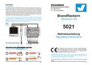
<strong>Licht</strong>-<strong>Sperrsignal</strong><br />
Colour Light Blocked Signal<br />
<strong>4027</strong>, <strong>4028</strong> (<strong>H0</strong>)<br />
<strong>4447</strong>, <strong>4448</strong> (N)<br />
<strong>4947</strong>, <strong>4028</strong> (TT)<br />
Betriebsanleitung<br />
Operating Instructions<br />
Nicht bestimmt für Kinder unter 14 Jahren. Enthält Kleinteile.<br />
Bei unsachgemäßem Gebrauch besteht Verletzungsgefahr<br />
durch funktionsbedingte scharfe Kanten und Spitzen! Bitte<br />
diese Betriebsanleitung gut verwahren.<br />
Not intended for children under 14 years of age. Contains small parts. At an<br />
incorrect use there exists danger of hurting because of cutting edges and<br />
tips! Please keep these Instructions in safe place.<br />
Ne convient pas aux enfants de moins de 14 ans. Contient des petites<br />
piéces.<br />
1
Einleitung<br />
Introduction<br />
Die Hobby -<strong>Licht</strong>-<strong>Sperrsignal</strong>e von Viessmann zeichnen sich durch ihr hervorragendes Preis-<br />
Lei-stungsverhältnis sowie durch einfache Montage und Anschlußmöglichkeit aus! Im am<br />
Signal angesetzten Antriebskasten befinden sich die elektronische Steuerung für die<br />
realistische An-steuerung der einzelnen <strong>Licht</strong>signalbilder sowie die Relais für die<br />
Zugbeeinflussung. Dieses macht den Anschluß der Signale so einfach. Das Motto heißt<br />
“Auspacken, Anschließen und Losfahren”. Elektronische Vorkenntnisse sind nicht notwendig!<br />
The Hobby colour light blocked signals from Viessmann convince by an excellent price-service<br />
relation and by an easy mounting and connecting. The foot box contains the electronic for a realistic<br />
controlling of the aspects as well as the relays for the train stop. For that reason the connection<br />
of this signals is so easy. The slogan is: unwrap, connect and go! There is no electronic<br />
previous know-how necessary.<br />
Aufstellung von <strong>Licht</strong>-<strong>Sperrsignal</strong>en<br />
Putting-up of Colour Light Blocked Signals<br />
<strong>Sperrsignal</strong>e gehören der Kategorie der Schutzsignale an und haben einen vielfältigen Aufgabenbereich.<br />
Sie stehen - in Fahrtrichtung gesehen - rechts vom Gleis. Ein großes Einsatzgebiet<br />
der <strong>Sperrsignal</strong>e liegt in Rangierbereichen. In der Praxis werden Güterwagen nach<br />
Richtungen beladen. Das heißt, ein Wagen muß eventuell in verschiedene Gleise einfahren<br />
und wird dort mit den jeweiligen Gütern für sein Fahrtziel beladen (siehe Abbildung 1). Der Wagen<br />
wird also z.B. von Gleis 1 aus bis hinter die Weiche von Gleis 4 befördert und dann auf Gleis<br />
4 geschoben. Der Rangierauftrag von einem Gleis zum anderen wird durch <strong>Sperrsignal</strong>e geregelt.<br />
<strong>Licht</strong>-<strong>Sperrsignal</strong>e gibt es in hoher und in niedriger Ausführung. Wo welche Bauform aufgestellt<br />
wird, hängt von der darzustellenden Epoche sowie von den örtlichen Gegebenheiten ab.<br />
In den fünfziger und sechziger Jahren gab es nur die hohe Ausführung der <strong>Licht</strong>-<strong>Sperrsignal</strong>e.<br />
Diese liegt jedoch im <strong>Licht</strong>raumprofil, d.h. in dem Bereich, in welchem ausschwenkende Waggons<br />
es umreißen könnten. Damit die verfügbare Gleislänge optimal genutzt werden kann,<br />
muß das <strong>Sperrsignal</strong> so nah wie möglich an die Weiche gesetzt werden - gerade in diesem Bereich<br />
kommt es aber verstärkt zu ausschwenkenden Waggons. Aus diesem Grund wurde ab<br />
ca. 1968 die niedrige Ausführung, der sogenannte “(Schotter-) Zwerg” eingeführt. Dieser steht<br />
außerhalb des <strong>Licht</strong>raumprofils. Heutzutage wird in der Regel nur noch die niedrige Ausführung<br />
aufgestellt. Hier noch einmal die Regeln in Kurzform:<br />
- Epoche III (bis 1968): Nur die hohe Ausführung der <strong>Sperrsignal</strong>e aufstellen. Im Bereich von<br />
Weichen und engen Kurven Aufstellung vermeiden oder nur in weitem<br />
Abstand zum Gleis (ca. 3,8 reale Meter von der Gleismitte) positionieren.<br />
- ab Epoche IV: In unmittelbarer Nähe von Weichen oder in Bereichen mit engen Kurven:<br />
niedrige Ausführung verwenden. Auch in anderen Fällen kann die<br />
niedrige Ausführung aufgestellt werden.<br />
Gleis 1<br />
track 1<br />
Gleis 2<br />
track 2<br />
Gleis 3<br />
track 3<br />
Gleis 4<br />
track 4<br />
2<br />
Abbildung 1<br />
Figure 1
The correct conventional connection of a blocked signal is shown in figure 2. The power supply<br />
occurs by the brown and the yellow wire. The blue wires with the coloured marks are switched<br />
by contacts (single keys, reed-contacts, switching rails or push button panels) to the brown<br />
wire. Depending on the key you press, you can see the signal aspect “shunting stop” or “shunting<br />
stop cancelled”. The two red wires of the Hobby-signal switch the power at the insulated<br />
stop track off, if the signal displays “shunting stop”.<br />
Abbildung 2<br />
Figure 2<br />
Das rechte<br />
Schienenprofil<br />
entspricht bei<br />
Märklin dem<br />
Mittelleiter!<br />
The right rail<br />
corresponds with<br />
the third rail of<br />
Märklin!<br />
ca. 2<br />
Loklängen<br />
approx. 2<br />
locomotive<br />
lengths<br />
Achtung!<br />
<strong>4027</strong><br />
<strong>4028</strong><br />
<strong>4447</strong><br />
<strong>4448</strong><br />
<strong>4947</strong><br />
Attention!<br />
Alle Anschlußarbeiten sind nur bei abgeschalteter<br />
Betriebsspannung durchzuführen!<br />
Make sure that the power supply is switched off when you connect the<br />
wires !<br />
Dieses Symbol kennzeichnet einen Schaltkontakt,<br />
z.B. einen Reed- (Magnet-) Schalter, Schaltgleis,<br />
Einzeltaster oder Tastenstellpult.<br />
This sign is used for a momentary switching contact<br />
like a reed contact, a switching track, a single momentary<br />
switch or a push button panel.<br />
In den Anschlußplänen dieser Anleitung finden Sie<br />
häufig das obenstehende Symbol. Es kennzeichnet<br />
eine Leitungsverbindung. Die sich hier kreuzenden<br />
Leitungen müssen an einer beliebigen Stelle ihres<br />
Verlaufs elektrisch leitend miteinander in Verbindung<br />
stehen. Der Verbindungspunkt muß also nicht<br />
exakt an der eingezeichneten Stelle sitzen, sondern<br />
kann z.B. zu einem Stecker, welcher sich an einer<br />
der kreuzenden Leitungen befindet, verlagert werden.<br />
Sh0<br />
Sh1<br />
Sekundär<br />
16 V ~<br />
Gefertigt nach<br />
VDE 0551<br />
EN 60742<br />
Primär 230 V 50/60 Hz<br />
Sekundär 52 VA max. 3,25 A<br />
IP 40 ta 25°C<br />
Nur für trockene Räume<br />
<strong>Licht</strong>transformator 5200<br />
Primär<br />
230 V ~<br />
Fahrstrom<br />
konventionell oder digital<br />
Track Power<br />
analog or digital<br />
Dieses Symbol neben dem Gleis kennzeichnet eine<br />
in Fahrtrichtung rechtsseitige Trennstelle (z.B. mit<br />
Isolierschienenverbindern). Bei Märklin-Gleisen entspricht<br />
dieses einer Mittelleiter-Trennstelle.<br />
This sign beside the track indicates a track insulation<br />
on the right rail (if you look in driving direction). If you<br />
use the Märklin system this must be a third rail insulation.<br />
In the connection diagrams of this instruction you<br />
can often see the above shown symbol. It describes<br />
a wire connection. The wires which here are crossing<br />
themselves have to be connected electrically at<br />
any point on their way. So the connection point<br />
doesn’t need to be exactly at the shown location. It<br />
can be moved e.g. to a plug which is connected to<br />
one of the crossing wires.<br />
5
Before mounting you have to make a functional test.To test the blocked signal you have to connect<br />
the yellow and the brown wire, each to one pole of a 14-16 V model train transformer<br />
(AC/DC) - for example Viessmann 5200. By alternating connection of the blue wires to the pole<br />
of the model train transformer on which the brown wire has been connected to, you get the<br />
following functions:<br />
Kabelfarbensystem<br />
Wire colour system<br />
Anschluß<br />
Connection<br />
Der konventionelle Anschluß der <strong>Sperrsignal</strong>e ist in Abbildung 2 dargestellt. Die Stromversorgung<br />
erfolgt über die beiden braunen und gelben Anschlußkabel. Die mit farbigen Markierungen<br />
versehenen blauen Kabel werden über Kontakte (Einzeltaster, Gleiskontakte, Schaltgleise<br />
oder Tastenstellpulte) gegen das braune Anschlußkabel geschaltet. Hiermit kann zwischen<br />
den Signalbildern “Halt! Fahrverbot” oder “Fahrverbot aufgehoben” umgeschaltet werden. Die<br />
beiden roten Anschlußkabel des Hobby-Signals schalten je nach Signalstellung den Strom im<br />
isolierten Halteabschnitt zu oder ab.<br />
4<br />
Blau mit roter Markierung<br />
blue with a red mark<br />
Sh0 (Halt! Fahrverbot)<br />
Sh0 (shunting stop)<br />
Blau mit gelber Markierung<br />
blue with a yellow mark<br />
Sh1 (Fahrverbot aufgehoben)<br />
Sh1 (shunting stop cancelled)<br />
Signal auf Sh0 (“Halt! Fahrverbot”)<br />
Shunting stop (red)<br />
Signal auf Sh1 (“Fahrverbot aufgehoben”)<br />
Shunting stop cancelled (yellow)<br />
Betriebsspannung “Phase”<br />
Power supply<br />
Betriebsspannung “Masse”<br />
Power supply “ground”<br />
Zugbeeinflussungskontakt<br />
Train stop contact<br />
Zugbeeinflussungskontakt<br />
Train stop contact<br />
Die Stromquellen müssen so abgesichert sein, daß es im Falle eines Kurzschlusses<br />
nicht zum Kabelbrand kommen kann. Verwenden Sie nur<br />
handelsübliche und nach VDE/EN gefertigte Modellbahntransformatoren!<br />
The power sources must be protected to prevent the risk of burning wires. Only use<br />
VDE/EN tested special model train transformers for the power supply!
Die <strong>Sperrsignal</strong>e werden in diesen Ausführungen jedoch auch für andere Einsatzzwecke verwendet,<br />
z.B. als Einfahr-<strong>Sperrsignal</strong> oder Falschfahr-Auftragssignal (nur niedrige Ausführung),<br />
an Gleiswagen, auf Drehbrücken von Drehscheiben, als Brückendeckungssignale sowie<br />
bei Abdeckung der unteren weißen bzw. hellgelben LED auch als Zugdeckungssignale an<br />
Bahnsteigen.<br />
Blocked signals are part of the group of protective signals and have got a wide range of responsibility.<br />
They are placed as a rule at the right side of the tracks. One application field of the<br />
blocked signals is using in shunting areas. The freight cars are loaded according to the direction<br />
of their destination. So one waggon has to enter several tracks and is loaded there with<br />
the goods (see figure 1). The waggon can be pulled from track 1 behind the turnout of track 4.<br />
Then it is pushed on track 4. The shunting instruction from one track to another is organized by<br />
the blocked signals.<br />
Colour blocked signals are available as dwarf and raised type. Where you have to use which<br />
kind of type, depends on the epoch you want to show and the local circumstances, too. In the<br />
fifties and sixties there only existed the raised type of the blocked signals. But this type normally<br />
stands in the provided clearance around the track, so the signal could be hurt by waggons<br />
which swing out. To exploit the track length best, you have to put the blocked signal very close to<br />
the turnout - the area, where waggons normally swing out. For this reason about 1968 the dwarf<br />
type of the blocked signal was developed. This type doesn’t touch the provided clearance<br />
around the track. Nowadays only this dwarf type is installed. Here is a short form of the rules for<br />
you:<br />
- epoch III (till 1968): Install only the raised blocked signal. Please avoid the insallation of<br />
these types near turnouts and sharp bends or put it in a distance of<br />
about 3.8 (real) meters near the track.<br />
- from epoch IV up: Near turnouts or in areas with sharp curves you should use the dwarf<br />
blocked signal. In other areas you can use both types.<br />
This type of blocked signals is also used for other tasks, for example as an entry blocked signal<br />
or reverse drive signal (only the dwarf type), beside waggon balances, on turntables, as bridge<br />
protect signal and as a train protect signal for platforms .<br />
Bezeichnung von <strong>Sperrsignal</strong>en<br />
Nomenclature for Blocked Signals<br />
<strong>Sperrsignal</strong>e, werden mit der Gleisnummer des Gleises bezeichnet, an dessen Ausfahrt sie<br />
stehen.<br />
Blocked signals are labeled by the same number as the track, at which exit they are placed.<br />
Funktionskontrolle<br />
Functional Test<br />
Vor der Montage ist eine Funktionskontrolle durchzuführen. Zum Testen des <strong>Sperrsignal</strong>es<br />
sind das gelbe und das braune Kabel vom Signal an je einem Pol eines 14-16<br />
V - Modellbahntransformators<br />
(AC/DC) - z.B. Viessmann 5200 - anzuschließen. Beim kurzzeitigen (abwechselnden!)<br />
Anschluß der blauen Kabel an den Pol des Trafos, an dem sich das braune Signalanschlußkabel<br />
befindet, ergeben sich folgende Funktionen:<br />
3
Ansteuerung über Digitalsysteme<br />
Controlling by digital systems<br />
Die Hobby-Signale können auch mit einem Digitalsystem angesteuert werden (Abbildung 3).<br />
Beim Anschluß der Signale an einen Digital-Decoder wie z.B. Viessmann 5211 (für Märklin-<br />
Digital bzw. das Motorola-Format) oder Viessmann 5212 für das NMRA (DCC)-Format ist<br />
darauf zu achten, daß die braune Signal-Masseleitung, welche am Versorgungstrafo der<br />
Hobby-Signale<br />
angeschlossen ist, auch mit der Digitalmasse verbunden ist. Der Decoder muß<br />
positive Schaltimpulse liefern! Dieses ist bei dem Decoder des Märklin-Digitalsystems (k83)<br />
sowie allen Viessmann-Decodern<br />
der Fall.<br />
Hobby signals can also be controlled by digital systems (see figure 3). If you connect the signals<br />
to digital decoders like Viessmann 5211 (for Märklin-Digital or the Motorola format) or the Viessmann<br />
5212 for the NMRA (DCC)-Format, it is necessary to connect the brown signal wire<br />
(ground), which is connected to the transformer, to the digital ground. The decoder has to send<br />
positive switching pulses. This is ensured by the Märklin digital decoder (k83) and all decoders<br />
made by Viessmann.<br />
ca. 2<br />
Loklängen<br />
approx. 2<br />
locomotive<br />
lengths<br />
Technische Daten<br />
Technical Data<br />
1 2 3 4 5 6 7 8<br />
Adresse<br />
E<br />
ON WnP<br />
Weichendecoder 5211<br />
Betriebsspannung Operating voltage<br />
14 - 16 V AC/DC<br />
Kontaktbelastbarkeit (der beiden roten Kabel) 2 A<br />
Max. contact load (the two red wires) 2 A<br />
4<br />
1<br />
Sh0<br />
3<br />
2<br />
Sh1<br />
Digitaldecoder mit<br />
positiven Schaltimpulsen<br />
Digital decoder with<br />
positive switching pulses<br />
Fahrstrom digital<br />
Track Power digital<br />
Maße des Antriebskastens (Länge x Breite x Höhe) 43 x 16 x 10,5 mm<br />
Size of the relay box (length x width x height) 43 x 16 x 10,5 mm<br />
6<br />
<strong>4027</strong><br />
<strong>4028</strong><br />
<strong>4447</strong><br />
<strong>4448</strong><br />
<strong>4947</strong><br />
Sekundär<br />
16 V ~<br />
Gefertigt nach<br />
VDE 0551<br />
EN 60742<br />
Primär 230 V 50/60 Hz<br />
Sekundär 52 VA max. 3,25 A<br />
IP 40 ta 25°C<br />
Nur für trockene Räume<br />
<strong>Licht</strong>transformator 5200<br />
Masseverbindung zwischen<br />
Signal und Digitalsystem!<br />
Ground connection between<br />
signal and digital system!<br />
Abbildung 3<br />
Figure 3<br />
Primär<br />
230 V ~<br />
Sachnummer 98655