Vollautomatische Bahnschranke H0 Fully Automatic Gate H0 5100 ...
Vollautomatische Bahnschranke H0 Fully Automatic Gate H0 5100 ...
Vollautomatische Bahnschranke H0 Fully Automatic Gate H0 5100 ...

Erfolgreiche ePaper selbst erstellen
Machen Sie aus Ihren PDF Publikationen ein blätterbares Flipbook mit unserer einzigartigen Google optimierten e-Paper Software.
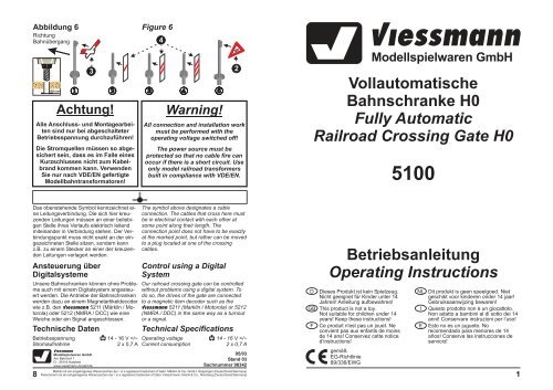
Abbildung 6<br />
Richtung<br />
Bahnübergang<br />
8<br />
Ø4 mm<br />
Das obenstehende Symbol kennzeichnet eine<br />
Leitungsverbindung. Die sich hier kreuzenden<br />
Leitungen müssen an einer beliebigen<br />
Stelle ihres Verlaufs elektrisch leitend<br />
miteinander in Verbindung stehen. Der Verbindungspunkt<br />
muss nicht exakt an der eingezeichneten<br />
Stelle sitzen, sondern kann<br />
z.B. zu einem Stecker an einer der kreuzenden<br />
Leitungen verlagert werden.<br />
Unsere <strong>Bahnschranke</strong>n können ohne Probleme<br />
auch mit einem Digitalsystem angesteuert<br />
werden. Die Antriebe der <strong>Bahnschranke</strong>n<br />
werden dazu an einem Magnetartikeldecoder<br />
wie z.B. den Viessmann 5211 (Märklin / Mo-<br />
torola) oder 5212 (NMRA / DCC) wie eine<br />
Weiche oder ein Signal angeschlossen.<br />
Technische Daten Technical Specifications<br />
Betriebsspannung 14 - 16 V =/~<br />
Stromaufnahme 2 x 0,7 A<br />
3<br />
Achtung!<br />
Alle Anschluss- und Montagearbeiten<br />
sind nur bei abgeschalteter<br />
Betriebsspannung durchzuführen!<br />
Die Stromquellen müssen so abgesichert<br />
sein, dass es im Falle eines<br />
Kurzschlusses nicht zum Kabelbrand<br />
kommen kann. Verwenden<br />
Sie nur nach VDE/EN gefertigte<br />
Modellbahntransformatoren!<br />
Ansteuerung über<br />
Digitalsysteme<br />
Figure 6<br />
Control using a Digital<br />
System<br />
Our railroad crossing gate can be controlled<br />
without problems using a digital system. To<br />
do so, the drives of the gate are connected<br />
to a magnetic item decoder such as the<br />
Viessmann 5211 (Marklin / Motorola) or 5212<br />
(NMRA / DDC) in the same way as a turnout<br />
or a signal.<br />
Operating voltage 14 - 16 V =/~<br />
Current consumption 2 x 0,7 A<br />
Viessmann<br />
Modellspielwaren GmbH<br />
Am Bahnhof 1<br />
D - 35116 Hatzfeld<br />
www.viessmann-modell.de<br />
Märklin ist ein eingetragenes Warenzeichen der / is a registered trademark of Gebr. Märklin & Cie. GmbH, Göppingen (Deutschland/ Germany)<br />
Fleischmann ist ein eingetragenes Warenzeichen der / is a registered trademark of Gebr. Fleischmann GmbH & Co., Nürnberg (Deutschland/ Germany)<br />
4<br />
Warning!<br />
All connection and installation work<br />
must be performed with the<br />
operating voltage switched off!<br />
The power source must be<br />
protected so that no cable fire can<br />
occur if there is a short circuit. Use<br />
only model railroad transformers<br />
built in compliance with VDE/EN.<br />
The symbol above designates a cable<br />
connection. The cables that cross here must<br />
be in electrical contact with each other at<br />
some point along their length. The<br />
connection point does not have to be exactly<br />
at the marked point, but rather can be moved<br />
to a plug located at one of the crossing<br />
cables.<br />
2<br />
05/03<br />
Stand 03<br />
Sachnummer 98342<br />
D Dieses Produkt ist kein Spielzeug.<br />
Nicht geeignet für Kinder unter 14<br />
Jahren! Anleitung aufbewahren!<br />
GB This product is not a toy.<br />
Not suitable for children under 14<br />
years! Keep these instructions!<br />
F Ce produit n'est pas un jouet. Ne<br />
convient pas aux enfants de moins<br />
de 14 ans! Conservez cette notice<br />
d’instructions!<br />
gemäß<br />
EG-Richtlinie<br />
89/336/EWG<br />
Viessmann<br />
Modellspielwaren GmbH<br />
<strong>Vollautomatische</strong><br />
<strong>Bahnschranke</strong> <strong>H0</strong><br />
<strong>Fully</strong> <strong>Automatic</strong><br />
Railroad Crossing <strong>Gate</strong> <strong>H0</strong><br />
<strong>5100</strong><br />
Betriebsanleitung<br />
Operating Instructions<br />
NL Dit produkt is geen speelgoed. Niet<br />
geschikt voor kinderen onder 14 jaar!<br />
Gebruiksaanwijzing bewaren!<br />
I Questo prodotto non è un giocattolo.<br />
Non adatto a bambini al di sotto dei 14<br />
anni! Conservare instruzioni per l’uso!<br />
E Esto no es un juguete. No<br />
recomendado para menores de 14<br />
años! Conserva las instrucciones de<br />
servicio!<br />
1
Lesen Sie vor der ersten Benutzung des Produktes<br />
bzw. dessen Einbau diese Bedienungsanleitung<br />
aufmerksam durch.<br />
Das Produkt richtig verwenden<br />
Dieses Schrankenmodell ist bestimmt<br />
- zum Einbau in Modelleisenbahnanlagen<br />
- zum Anschluss an einen zugelassenen Modellbahntransformator<br />
bzw. an einer damit<br />
versorgten elektrischen Steuerung<br />
- zum Betrieb in trockenen Räumen<br />
Jeder darüber hinausgehende Gebrauch gilt<br />
als nicht bestimmungsgemäß. Für hieraus<br />
resultierende Schäden haftet der Hersteller<br />
nicht; das Risiko hierfür trägt allein der Benutzer.<br />
2<br />
D GB<br />
Wichtige Hinweise! Important Information!<br />
Zur Sicherung von Bahnübergängen durch<br />
Schrankenwärter wurden früher wie heute<br />
<strong>Bahnschranke</strong>n verwendet. Diese Schranken<br />
wurden über Seilzüge durch den Schrankenwärter<br />
fernbedient. Bis in die heutige Zeit haben<br />
sich diese Bahnübergänge beim Vorbild<br />
halten können, allerdings werden es immer<br />
weniger, da alle handbetätigten Bahnübergänge<br />
nach und nach durch moderne Blinkzeichenanlagen<br />
ersetzt werden.<br />
Read the operating instructions carefully<br />
before using the product for the first time or<br />
installing it.<br />
Using the product correctly<br />
Einleitung Introduction<br />
Das Modell The Model<br />
Das Viessmann - Modell einer <strong>Bahnschranke</strong><br />
gibt die Vorbildsituation modellgerecht wieder<br />
und ist ein Schmuckstück auf jeder Anlage.<br />
Die beiden Schrankenbäume werden<br />
durch je einen Unterflur-Kompaktantrieb angetrieben,<br />
welche diese vorbildgerecht langsam<br />
heben und senken.<br />
Da jeder Schrankenbaum einzeln angetrieben<br />
wird, kann die Schranke freizügig eingesetzt<br />
und jeder Betriebssituation angepasst<br />
werden. Übergänge im Winkel von 45°,<br />
mehrgleisige Übergänge oder der Einsatz<br />
von vier Schrankenbäumen als gegenschlägige<br />
Schranke für sehr breite Straßen sind<br />
kein Problem (Widerlager sind nicht notwendig,<br />
Schrankenbäume stehen ohne Stütze in<br />
der Endlage waagerecht).<br />
Ein Gleisfüllstück sowie Rampen auf das<br />
Gleisniveau liegen bei. Durch die Rampenfüße<br />
(6) kann das Niveau der Rampe für<br />
Bettungsgleise noch erhöht werden.<br />
Die beiliegenden Verkehrsschilder sind be-<br />
This model of a railroad gate is intended<br />
- for installation in model railroad layouts.<br />
- for connection to an authorized model<br />
railroad transformer or an electrical control<br />
system connected to one.<br />
- for operation in a dry area.<br />
Using the product for any other purpose is<br />
not approved and is considered incorrect.<br />
The manufacturer cannot be held responsible<br />
for any damage resulting from the<br />
improper use of this product; liability in such<br />
a case rests with the user.<br />
Today, as in the past, attendants use railroad<br />
gates to secure railroad crossings. These<br />
gates are operated remotely by the<br />
attendants via cables. These railroad<br />
crossings have kept their original<br />
appearance to this very day, although there<br />
are fewer today because manually operated<br />
railroad crossings have been replaced by<br />
modern flashing light systems.<br />
The viessmann model of a railroad crossing<br />
gate is a true representation of the actual<br />
situation and is an enrichment to any model<br />
layout. Driven by a compact drive installed<br />
underneath each cross beam, the cross<br />
beams rise and lower at a representative<br />
slow speed.<br />
Because each cross beam is driven<br />
individually, the gate can be installed as<br />
desired and adapted to any operating<br />
situation. Crossings at an angle of 45°,<br />
multiple-track crossings, or the use of four<br />
cross beams across from each other as a<br />
gate for very wide streets is no problem<br />
(rests are not necessary, the cross beams<br />
remain horizontal in the end position without<br />
support).<br />
A track filler piece as well as ramps for the<br />
track level are included. For roadbed tracks<br />
you can adjust the high of the ramps by the<br />
ramp sockets (6).<br />
The included traffic signs are already printed.<br />
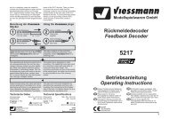
Abbildung 6 Figure 6<br />
2 Andreaskreuze mit Blinkelektronik 5065<br />
2 warning lights with blinking electronics<br />
9) Die Antriebe der <strong>Bahnschranke</strong> verfügen<br />
über jeweils einen zusätzlichen Schaltkontakt.<br />
Dieser kann genutzt werden um z.B.<br />
eine Blinkelektronik für Andreaskreuze<br />
(z.B. 5835) zu steuern. Hierzu wird eine<br />
der beiden Stromversorgungsleitungen der<br />
Blinkelektronik über den Kontakt von<br />
einem Antrieb geführt.<br />
Montage der<br />
Verkehrsschilder<br />
1) Für die Verwendung der Schilder in den<br />
Epochen II und III kürzen Sie zunächst die<br />
Warnbaken (4) und die Andreaskreuze (3)<br />
an den vorgegebenen Bruchkanten auf<br />
der Rückseite der Schilder. Eventuell mit<br />
einem scharfen Messer vorritzen!<br />
2) Kleben Sie die Andreaskreuze mit handelsüblichem<br />
Polystyrolkleber an die entsprechenden<br />
Masten. Beachten Sie hierbei,<br />
dass in den Epochen II und III das Andreaskreuz<br />
(3) um 90° gedreht am Mast<br />
befestigt wurde, wobei die kurzen Schenkel<br />
nach unten zeigten.<br />
3) Bohren Sie an den dafür vorgesehenen<br />
Stellen Löcher mit einem Durchmesser<br />
von 4 mm und montieren Sie die Schilder<br />
in der richtigen Reihenfolge (siehe Abbildung<br />
6). Der Regelabstand zwischen<br />
den Warnbaken beträgt beim Vorbild 80 m<br />
(in <strong>H0</strong> also 92 cm). Wenn die örtlichen Gegebenheiten<br />
es erfordern, sind aber auch<br />
kürzere Abstände erlaubt.<br />
4) Bei beengten Platzverhältnissen können<br />
Sie auch die dreistreifige Warnbake (4) mit<br />
einem Messer vom eigenen Mast abtrennen<br />
und unten an den Mast des Verkehrsschildes<br />
(2) kleben.<br />
B<br />
1 2 3 4<br />
5065<br />
Trafo<br />
14-16V<br />
AC/DC<br />
Installing the Traffic Signs<br />
1) To use the signs in periods II and III, first<br />
shorten the warning sign (4) and the St.<br />
Andrew's crosses (3) at the specified<br />
breaking edges on the rear of the signs. If<br />
necessary, first cut an indentation with a<br />
sharp knife!<br />
2) Glue the Andrew's crosses with standard<br />
polystyrene glue to their respective poles.<br />
Please note that in periods II and III the St.<br />
Andrew's cross (3) was attached at a 90°<br />
angle on the pole, with the short shanks<br />
pointing downwards.<br />
3) Drill holes with a diameter of 4 mm at the<br />
positions desired and install the signs in<br />
the correct sequence (see Figure 6). The<br />
standard distance between the warning<br />
signs in reality is 80 m (92 cm in <strong>H0</strong><br />
scale). Shorter distances are also permitted<br />
when the local situation requires it.<br />
4) If space is tight, you can also remove the<br />
warning sign with three stripes (4) from its<br />
pole using a knife and glue it at the bottom<br />
on the pole of the traffic sign (2).<br />
4-fach-Blinkgerät 5065<br />
A<br />
16 V AC/DC<br />
B<br />
zum<br />
Schaltkontakt<br />
to the<br />
switching<br />
contact<br />
9) The drive units of the railroad crossing<br />
gates are including an additional switching<br />
contact. This can be used to control the<br />
blinking electronics of warning lights (f.ex.<br />
5835). For that please connect one of the<br />
wires for the electric current of the blinking<br />
electronic with the contact of the drive<br />
unit.<br />
7
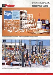
Anschluss Connection<br />
Abbildung 4 Figure 4<br />
Abbildung 5 Figure 5<br />
6<br />
öffnen<br />
open<br />
braun / brown<br />
mindestens<br />
eine Zuglänge<br />
at least one<br />
train length<br />
öffnen<br />
open<br />
schließen<br />
close<br />
blau mit roter Markierung / blue (red marking)<br />
mindestens eine<br />
Zuglänge<br />
at least<br />
one train length<br />
schließen<br />
close<br />
blau / blue<br />
blau / blue<br />
blau mit roter Markierung<br />
blue with red marking<br />
blau mit roter Markierung / blue (red marking)<br />
blau mit grüner Markierung / blue (green marking)<br />
blau mit grüner Markierung<br />
blue with green marking<br />
Elektr. Relais Relais 5552<br />
gelb / yellow<br />
braun / brown<br />
blau / blue<br />
gelb / yellow<br />
braun / brown<br />
gelb / yellow<br />
mindestens<br />
eine Zuglänge<br />
at least one<br />
train length<br />
mindestens<br />
eine Zuglänge<br />
at least one<br />
train length<br />
blau / blue<br />
schließen<br />
close<br />
schließen<br />
close<br />
braun / brown<br />
öffnen<br />
open<br />
blau / blue<br />
öffnen<br />
open<br />
16 V~ AC/DC<br />
16 V~ AC/DC<br />
reits fertig bedruckt. Für den Einsatz der<br />
Schranke in den Epochen II - III sind an den<br />
Andreaskreuzen und den Warnbaken<br />
Bruchkanten angebracht, um diese den<br />
damaligen Straßenverkehrsvorschriften<br />
entsprechend kürzen zu können.<br />
Inhalt Contents<br />
Nehmen Sie die <strong>Bahnschranke</strong>n (1) vorsichtig<br />
aus der Verpackung.<br />
Vor der Montage ist eine Funktionskontrolle<br />
durchzuführen. Zum Testen der <strong>Bahnschranke</strong>n<br />
stecken Sie diese bitte zunächst gemäß<br />
Abbildung 2 (siehe Seite 4) vorsichtig auf die<br />
Anschlussstecker (15) auf. Dabei keine Gewalt<br />
anwenden! Das gelbe Kabel der Stecker<br />
schließen Sie nun an einen Pol eines 16 V-<br />
Modellbahntransformators (AC/DC) - z.B.<br />
Viessmann 5200 - an. Beim kurzzeitigen (abwechselnden!)<br />
Anschluss der blauen Kabel<br />
an den anderen Pol des Trafos ergeben sich<br />
folgende Funktionen:<br />
10<br />
Breaking edges are provided on the St.<br />
Andrew's crosses and the warning signs, so<br />
that is possible to shorten the signs<br />
appropriately to fit the traffic regulations of<br />
periods II - III.<br />
Bitte prüfen Sie vor dem Einbau, ob der Check the contents of the package to ensure<br />
Packungsinhalt vollständig ist! Es befinden that is complete before assembly!<br />
The<br />
sich folgende Teile in der Verpackung: following parts are included in the package:<br />
Pos. Bezeichnung Description<br />
Anzahl<br />
Pos.<br />
Quantity<br />
1 <strong>Bahnschranke</strong> mit Antrieb<br />
Crossing gate with drive unit 2<br />
2 Verkehrsschild mit Mast<br />
Traffic sign with post<br />
2<br />
3 Andreaskreuz mit Mast<br />
St. Andrew's cross with pole 2<br />
4 Warnbaken mit Mast<br />
Warning sign with pole<br />
12<br />
5 Rampe<br />
Ramp<br />
2<br />
6 Rampenfuß<br />
Ramp-socket<br />
4<br />
7 Gleiszwischenstück<br />
Infill Piece<br />
1<br />
8 Gleiszwischenstück mit Kabel Infill piece with cable<br />
1<br />
9 Befestigungsring für Antrieb Attachment ring for drive unit 2<br />
10 Schrankenbaumwiderlager<br />
Cross beam rest<br />
2<br />
11 Oberes Sockelstück für Widerlager Upper part of the base<br />
2<br />
12 Unteres Sockelstück für Widerlager Lower part of the base<br />
2<br />
13 Oberes Sockelstück für Bahnschr. Upper part of the gate socket 2<br />
14 Unteres Sockelstück für Bahnschr. Lower part of the gate socket 2<br />
15<br />
Anschlussstecker<br />
Connection plug<br />
2<br />
Funktionskontrolle Function Check<br />
Abbildung 1 Figure 1<br />
blaues Kabel mit roter Markierung<br />
blue cable with red marking<br />
Carefully remove the railroad gates (1) from<br />
the package.<br />
Check for proper functioning before<br />
assembly. To test the railroad gate, carefully<br />
insert the plug (15) as shown in Figure 2<br />
(page 4). Do not use force! Then connect the<br />
yellow cable of the plug to one pole of a 16V<br />
model train transformer (AC/DC), such as<br />
the Viessmann 5200. If you briefly connect<br />
(alternating!) the blue cable to the other pole<br />
of the transformer, the following functions are<br />
performed:<br />
blaues Kabel mit grüner Markierung<br />
blue cable with green marking<br />
1 Schranken öffnen<br />
Schranken schließen<br />
open gate<br />
close gate<br />
3
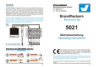
Abbildung 2 Figure 2<br />
Montage Assembly<br />
4<br />
1<br />
15<br />
10<br />
blau mit roter<br />
Markierung<br />
blue with red<br />
marking<br />
blau mit grüner<br />
Markierung<br />
blue with green<br />
marking<br />
gelb<br />
yellow<br />
1) Prüfen Sie vor dem Einbau der <strong>Bahnschranke</strong>n<br />
(1) wie im Punkt “Funktionskontrolle”<br />
beschrieben deren einwandfreie<br />
Funktion.<br />
2) Zeichnen Sie die Positionen der Bohrungen<br />
für die Schranken (1) und die Widerlager<br />
(10) mit Hilfe der rechts abgedruckten<br />
Schablone an. Die Mittelpunkte der<br />
Bohrungen müssen einen Abstand von 46<br />
mm haben.<br />
3) Bohren Sie an den angezeichneten Stellen<br />
jeweils zwei Löcher mit einem Durchmesser<br />
von 12 mm (für die Schranken)<br />
und 4 mm (für die Widerlager).<br />
4) Stecken Sie die Schranken mit dem Antrieb<br />
von oben durch die großen Bohrungen.<br />
Die Befestigungsringe (9) werden nun<br />
von unten so auf die Antriebe aufgeschoben,<br />
dass die Rastnasen um 90° zu<br />
der Riffelung am Gehäuse der Antriebe<br />
verdreht sind. Stehen nun die vier Kunststoff-Laschen<br />
des Befestigungsringes mit<br />
der Anlagenplatte unter mechanischer<br />
Spannung, wird der Ring so gedreht, dass<br />
die Nasen in der Riffelung des Antriebsgehäuses<br />
für einen festen Halt sorgen. Hierbei<br />
sollten Sie die Sockel der <strong>Bahnschranke</strong><br />
von oben festhalten.<br />
5) Die Widerlager werden in die 4 mm - Bohrungen<br />
eingesteckt.<br />
6) Das Gleisfüllstück (7 bzw. 8) wird auf die<br />
Schwellen zwischen den Schienenprofilen<br />
im Bereich des Bahnüberganges aufgeklebt.<br />
Bei Zweischienen-Gleisen (Fleischmann,<br />
Trix, Roco, Peco, Lima usw.) verwenden<br />
Sie bitte das Gleiszwischenstück (7) ohne<br />
Metallstreifen und ohne Anschlusskabel.<br />
Für Mittelleitergleise (Märklin C, M und K,<br />
Trix Express) verwenden Sie bitte das<br />
Schranke öffnen<br />
open crossing gates<br />
Schranke schließen<br />
close crossing gates<br />
Betriebsspannung Antrieb<br />
operating voltage for driving unit<br />
1) Check that the railroad gates (1) function<br />
properly as described under "Function<br />
check" before installing them.<br />
2) Mark the positions for the holes to be<br />
drilled for the gates (1) and the rests (10)<br />
using the pattern printed on the right side.<br />
The center points of the holes must be 46<br />
mm from each other.<br />
3) Drill two holes for each gate at the marked<br />
positions with a diameter of 12 mm (for the<br />
gates) and 4 mm (for the rests).<br />
4) Insert the gates with the drive from above<br />
through the large holes. Then place the<br />
attachment rings (9) on to the drives so<br />
that the catches are at a 90° angle to the<br />
ridges on the housing of the drives. When<br />
the four plastic straps of the attachment<br />
ring are mechanically clamped to the<br />
layout board, turn the ring so that the<br />
catches provide a firm hold in the ridges of<br />
the drive housing. You should hold the<br />
base of the railroad gate while doing so.<br />
5) Insert the rests into the 4 mm holes.<br />
6) Glue the track filling piece (7 resp. 8) on<br />
the ties between the tracks in the area of<br />
the railroad crossing. For two-rail-tracks<br />
(Fleischmann, Trix, Roco, Lima,...) please<br />
use the track filling piece 7 without metalstripe<br />
and without wire. For three-railtracks<br />
(Märklin C, M and K, Trix Express)<br />
please use the track filling piece 8 with<br />
metal-stripe and with red wire. The red<br />
connecting wire has to go between the<br />
sleepers to the lower side of the layout<br />
(first drill a hole). Than connect it to the<br />
third-rail-current (Märklin: red). To build<br />
railroad gate with more than one track, we<br />
offer the completition-sets 5101 (two-railtracks)<br />
and 5102 (three-rail-tracks). Both<br />
of them are including another track filling<br />
90º<br />
mit/ with 11<br />
Ø5mm<br />
46 mm<br />
mit/ with<br />
11 + 12<br />
Ø 5,5 mm<br />
Widerlager<br />
Ø12mm rest Ø4mm<br />
Schranke<br />
railroad gate<br />
Bohrschablone<br />
Drilling Pattern<br />
(lösen)<br />
9<br />
Gleiszwischenstück (8) mit Metallstreifen piece.<br />
und mit rotem Anschlusskabel. Das rote The ramps (5) allow model automobiles to<br />
Anschlusskabel führen Sie zwischen den reach track level.<br />
Schwellen nach unten (eventuell zuvor ein 7) Insert the connection plug (15) carefully<br />
Loch bohren) und schließen es am<br />
into the drive of the cross beam from<br />
Mittelleiter-Fahrstromanschluss (rot bei below as shown in Figure 2. Hold the<br />
Märklin) an. Zum Erstellen von breiteren cross beam firmly at its base from above<br />
oder mehrgleisigen Übergängen gibt es while doing this.<br />
unter der Art.-Nr. 5101 (Zweileiter) und 8) Now close the railroad gate as shown in<br />
Art.-Nr. 5102 (Mittelleiter) einen<br />
Figure 4 and Figure 5. An electronic relay<br />
Ergänzungssatz mit jeweils einem<br />
5552 is required for two-track operation.<br />
entsprechenden Gleiszwischenstück. This is necessary so that when two trains<br />
Die Rampen (5) dienen als Auffahrt für die approaching each other cross the railroad<br />
Modellautos auf das Gleisniveau.<br />
crossing at the same time, the beams do<br />
7) Stecken Sie die Anschlussstecker (15) ge- not open until both trains have left the<br />
mäß Abbildung 2 vorsichtig von unten auf crossing.<br />
die Antriebe der <strong>Bahnschranke</strong>n. Halten<br />
Sie diese dabei von oben am Sockel fest.<br />
8) Schließen Sie nun die <strong>Bahnschranke</strong> gemäß<br />
den Abbildungen 4 oder 5 an. Bei<br />
zweigleisigem Betrieb ist ein elektronisches<br />
Relais 5552 erforderlich. Dadurch<br />
wird erreicht, dass bei gleichzeitigem<br />
Überqueren des Bahnüberganges von<br />
zwei entgegenkommenden Zügen die<br />
Schranken erst wieder geöffnet werden,<br />
wenn beide Züge den Bahnübergang<br />
verlassen haben.<br />
Abbildung 3 Figure 3<br />
13<br />
14<br />
1<br />
6<br />
5<br />
12<br />
10<br />
11<br />
6<br />
1<br />
13<br />
14<br />
7<br />
6<br />
10<br />
Zum Mittelleiter<br />
To the centre rail<br />
6<br />
11<br />
5<br />
12<br />
8<br />
5