Vollautomatische Bahnschranke H0 Fully Automatic Gate H0 5100 ...
Vollautomatische Bahnschranke H0 Fully Automatic Gate H0 5100 ...
Vollautomatische Bahnschranke H0 Fully Automatic Gate H0 5100 ...

Erfolgreiche ePaper selbst erstellen
Machen Sie aus Ihren PDF Publikationen ein blätterbares Flipbook mit unserer einzigartigen Google optimierten e-Paper Software.
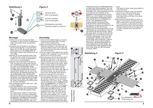
Abbildung 2 Figure 2<br />
Montage Assembly<br />
4<br />
1<br />
15<br />
10<br />
blau mit roter<br />
Markierung<br />
blue with red<br />
marking<br />
blau mit grüner<br />
Markierung<br />
blue with green<br />
marking<br />
gelb<br />
yellow<br />
1) Prüfen Sie vor dem Einbau der <strong>Bahnschranke</strong>n<br />
(1) wie im Punkt “Funktionskontrolle”<br />
beschrieben deren einwandfreie<br />
Funktion.<br />
2) Zeichnen Sie die Positionen der Bohrungen<br />
für die Schranken (1) und die Widerlager<br />
(10) mit Hilfe der rechts abgedruckten<br />
Schablone an. Die Mittelpunkte der<br />
Bohrungen müssen einen Abstand von 46<br />
mm haben.<br />
3) Bohren Sie an den angezeichneten Stellen<br />
jeweils zwei Löcher mit einem Durchmesser<br />
von 12 mm (für die Schranken)<br />
und 4 mm (für die Widerlager).<br />
4) Stecken Sie die Schranken mit dem Antrieb<br />
von oben durch die großen Bohrungen.<br />
Die Befestigungsringe (9) werden nun<br />
von unten so auf die Antriebe aufgeschoben,<br />
dass die Rastnasen um 90° zu<br />
der Riffelung am Gehäuse der Antriebe<br />
verdreht sind. Stehen nun die vier Kunststoff-Laschen<br />
des Befestigungsringes mit<br />
der Anlagenplatte unter mechanischer<br />
Spannung, wird der Ring so gedreht, dass<br />
die Nasen in der Riffelung des Antriebsgehäuses<br />
für einen festen Halt sorgen. Hierbei<br />
sollten Sie die Sockel der <strong>Bahnschranke</strong><br />
von oben festhalten.<br />
5) Die Widerlager werden in die 4 mm - Bohrungen<br />
eingesteckt.<br />
6) Das Gleisfüllstück (7 bzw. 8) wird auf die<br />
Schwellen zwischen den Schienenprofilen<br />
im Bereich des Bahnüberganges aufgeklebt.<br />
Bei Zweischienen-Gleisen (Fleischmann,<br />
Trix, Roco, Peco, Lima usw.) verwenden<br />
Sie bitte das Gleiszwischenstück (7) ohne<br />
Metallstreifen und ohne Anschlusskabel.<br />
Für Mittelleitergleise (Märklin C, M und K,<br />
Trix Express) verwenden Sie bitte das<br />
Schranke öffnen<br />
open crossing gates<br />
Schranke schließen<br />
close crossing gates<br />
Betriebsspannung Antrieb<br />
operating voltage for driving unit<br />
1) Check that the railroad gates (1) function<br />
properly as described under "Function<br />
check" before installing them.<br />
2) Mark the positions for the holes to be<br />
drilled for the gates (1) and the rests (10)<br />
using the pattern printed on the right side.<br />
The center points of the holes must be 46<br />
mm from each other.<br />
3) Drill two holes for each gate at the marked<br />
positions with a diameter of 12 mm (for the<br />
gates) and 4 mm (for the rests).<br />
4) Insert the gates with the drive from above<br />
through the large holes. Then place the<br />
attachment rings (9) on to the drives so<br />
that the catches are at a 90° angle to the<br />
ridges on the housing of the drives. When<br />
the four plastic straps of the attachment<br />
ring are mechanically clamped to the<br />
layout board, turn the ring so that the<br />
catches provide a firm hold in the ridges of<br />
the drive housing. You should hold the<br />
base of the railroad gate while doing so.<br />
5) Insert the rests into the 4 mm holes.<br />
6) Glue the track filling piece (7 resp. 8) on<br />
the ties between the tracks in the area of<br />
the railroad crossing. For two-rail-tracks<br />
(Fleischmann, Trix, Roco, Lima,...) please<br />
use the track filling piece 7 without metalstripe<br />
and without wire. For three-railtracks<br />
(Märklin C, M and K, Trix Express)<br />
please use the track filling piece 8 with<br />
metal-stripe and with red wire. The red<br />
connecting wire has to go between the<br />
sleepers to the lower side of the layout<br />
(first drill a hole). Than connect it to the<br />
third-rail-current (Märklin: red). To build<br />
railroad gate with more than one track, we<br />
offer the completition-sets 5101 (two-railtracks)<br />
and 5102 (three-rail-tracks). Both<br />
of them are including another track filling<br />
90º<br />
mit/ with 11<br />
Ø5mm<br />
46 mm<br />
mit/ with<br />
11 + 12<br />
Ø 5,5 mm<br />
Widerlager<br />
Ø12mm rest Ø4mm<br />
Schranke<br />
railroad gate<br />
Bohrschablone<br />
Drilling Pattern<br />
(lösen)<br />
9<br />
Gleiszwischenstück (8) mit Metallstreifen piece.<br />
und mit rotem Anschlusskabel. Das rote The ramps (5) allow model automobiles to<br />
Anschlusskabel führen Sie zwischen den reach track level.<br />
Schwellen nach unten (eventuell zuvor ein 7) Insert the connection plug (15) carefully<br />
Loch bohren) und schließen es am<br />
into the drive of the cross beam from<br />
Mittelleiter-Fahrstromanschluss (rot bei below as shown in Figure 2. Hold the<br />
Märklin) an. Zum Erstellen von breiteren cross beam firmly at its base from above<br />
oder mehrgleisigen Übergängen gibt es while doing this.<br />
unter der Art.-Nr. 5101 (Zweileiter) und 8) Now close the railroad gate as shown in<br />
Art.-Nr. 5102 (Mittelleiter) einen<br />
Figure 4 and Figure 5. An electronic relay<br />
Ergänzungssatz mit jeweils einem<br />
5552 is required for two-track operation.<br />
entsprechenden Gleiszwischenstück. This is necessary so that when two trains<br />
Die Rampen (5) dienen als Auffahrt für die approaching each other cross the railroad<br />
Modellautos auf das Gleisniveau.<br />
crossing at the same time, the beams do<br />
7) Stecken Sie die Anschlussstecker (15) ge- not open until both trains have left the<br />
mäß Abbildung 2 vorsichtig von unten auf crossing.<br />
die Antriebe der <strong>Bahnschranke</strong>n. Halten<br />
Sie diese dabei von oben am Sockel fest.<br />
8) Schließen Sie nun die <strong>Bahnschranke</strong> gemäß<br />
den Abbildungen 4 oder 5 an. Bei<br />
zweigleisigem Betrieb ist ein elektronisches<br />
Relais 5552 erforderlich. Dadurch<br />
wird erreicht, dass bei gleichzeitigem<br />
Überqueren des Bahnüberganges von<br />
zwei entgegenkommenden Zügen die<br />
Schranken erst wieder geöffnet werden,<br />
wenn beide Züge den Bahnübergang<br />
verlassen haben.<br />
Abbildung 3 Figure 3<br />
13<br />
14<br />
1<br />
6<br />
5<br />
12<br />
10<br />
11<br />
6<br />
1<br />
13<br />
14<br />
7<br />
6<br />
10<br />
Zum Mittelleiter<br />
To the centre rail<br />
6<br />
11<br />
5<br />
12<br />
8<br />
5