Licht-Einfahrsignal 4022 (H0) 4442 (N) 4942 (TT)
Licht-Einfahrsignal 4022 (H0) 4442 (N) 4942 (TT)
Licht-Einfahrsignal 4022 (H0) 4442 (N) 4942 (TT)

Sie wollen auch ein ePaper? Erhöhen Sie die Reichweite Ihrer Titel.
YUMPU macht aus Druck-PDFs automatisch weboptimierte ePaper, die Google liebt.
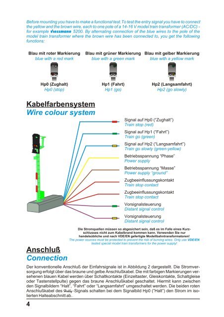
Before mounting you have to make a functional test.To test the entry signal you have to connect<br />
the yellow and the brown wire, each to one pole of a 14-16 V model train transformer (AC/DC) -<br />
for example Viessmann 5200. By alternating connection of the blue wires to the pole of the<br />
model train transformer where the brown wire has been connected to, you get the following<br />
functions:<br />
Kabelfarbensystem<br />
Wire colour system<br />
Anschluß<br />
Connection<br />
4<br />
Blau mit roter Markierung<br />
blue with a red mark<br />
Hp0 (Zughalt)<br />
Hp0 (stop)<br />
Blau mit grüner Markierung<br />
blue with a green mark<br />
Hp1 (Fahrt)<br />
Hp1 (go)<br />
Blau mit gelber Markierung<br />
blue with a yellow mark<br />
Hp2 (Langsamfahrt)<br />
Hp2 (go slowly)<br />
Signal auf Hp0 (“Zughalt”)<br />
Train stop (red)<br />
Signal auf Hp1 (“Fahrt”)<br />
Train go (green)<br />
Signal auf Hp2 (“Langsamfahrt”)<br />
Train go slowly (green-yellow)<br />
Betriebsspannung “Phase”<br />
Power supply<br />
Betriebsspannung “Masse”<br />
Power supply “ground”<br />
Zugbeeinflussungskontakt<br />
Train stop contact<br />
Zugbeeinflussungskontakt<br />
Train stop contact<br />
Vorsignalsteuerung<br />
Distant signal control<br />
Vorsignalsteuerung<br />
Distant signal control<br />
Die Stromquellen müssen so abgesichert sein, daß es im Falle eines Kurzschlusses<br />
nicht zum Kabelbrand kommen kann. Verwenden Sie nur<br />
handelsübliche und nach VDE/EN gefertigte Modellbahntransformatoren!<br />
The power sources must be protected to prevent the risk of burning wires. Only use VDE/EN<br />
tested special model train transformers for the power supply!<br />
Der konventionelle Anschluß der <strong>Einfahrsignal</strong>e ist in Abbildung 2 dargestellt. Die Stromversorgung<br />
erfolgt über das braune und gelbe Anschlußkabel. Die mit farbigen Markierungen versehenen<br />
blauen Kabel werden über Schaltkontakte (Einzeltaster, Gleiskontakte, Schaltgleise<br />
oder Tastenstellpulte) gegen das braune Anschlußkabel geschaltet. Hiermit kann zwischen<br />
den Signalbildern “Halt”, “Fahrt” oder “Langsamfahrt” umgeschaltet werden. Die beiden roten<br />
Anschlußkabel des Hobby-Signals schalten bei dem Signalbild Hp0 (”Halt”) den Strom im isolierten<br />
Halteabschnitt ab..