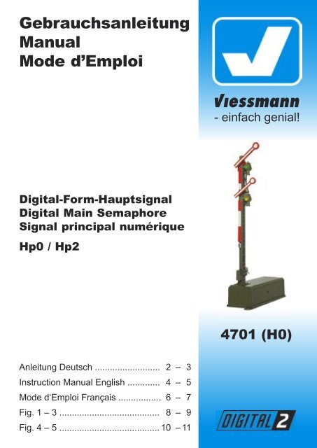
Gebrauchsanleitung Manual Mode d'Emploi
Gebrauchsanleitung Manual Mode d'Emploi
Gebrauchsanleitung Manual Mode d'Emploi

Create successful ePaper yourself
Turn your PDF publications into a flip-book with our unique Google optimized e-Paper software.
<strong>Gebrauchsanleitung</strong><br />
<strong>Manual</strong><br />
<strong>Mode</strong> d’Emploi<br />
Digital-Form-Hauptsignal<br />
Digital Main Semaphore<br />
Signal principal numérique<br />
Hp0 / Hp2<br />
Anleitung Deutsch .......................... 2 – 3<br />
Instruction <strong>Manual</strong> English ............. 4 – 5<br />
<strong>Mode</strong> d‘Emploi Français ................ . 6 – 7<br />
Fig. 1 – 3 ........................................ 8 – 9<br />
Fig. 4 – 5 ........................................ 10 – 11<br />
4701 (H0)
D<br />
2<br />
Digital-Form-Hauptsignal<br />
Hp0 / Hp2<br />
Lesen Sie vor der ersten Benutzung des<br />
Produktes bzw. dessen Einbau die Be dienungs<br />
anleitung aufmerksam durch. Das<br />
Produkt darf ausschließlich dieser Anleitung<br />
gemäß verwendet werden.<br />
Das Signalmodell ist konstruiert zum Einbau<br />
in <strong>Mode</strong>lleisenbahnanlagen und zum<br />
Anschluss an einen zugelassenen Mo dellbahn<br />
trans formator bzw. an einer damit versorgten<br />
elektrischen (digitalen) Steuerung in<br />
trockenen Räumen.<br />
Jeder darüber hinausgehende Gebrauch gilt<br />
als nicht bestimmungsgemäß. Für hieraus<br />
resultierende Schäden haftet der Hersteller<br />
nicht; das Risiko hierfür trägt allein der<br />
Benutzer.<br />
Einleitung<br />
Viessmann-Digital-Formsignale zeichnen sich<br />
durch ihr hervorragendes Preis-Leistungs-<br />
Verhältnis sowie durch einfache Montage und<br />
Anschlussmöglichkeit aus! Im angesetzten<br />
Antriebskasten befinden sich der Spezialantrieb<br />
zur Erzeugung der typischen langsamen<br />
Bewegung, der Digitaldecoder sowie der Kontakt<br />
für die Zugbeeinflussung. Das Motto heißt<br />
„Auspacken, Anschließen und Losfah ren“.<br />
Elektrische Vorkenntnisse sind nicht notwendig!<br />
Die Digital-Form-Haupt sig na le können so wohl<br />
separat, als auch in Kombi na tion mit Digital-Form-<br />
Vor- oder Sperr sig na len aufgestellt werden.<br />
Aufstellung von Form-<br />
Hauptsignalen<br />
Hauptsignale stehen in Deutschland in der Regel<br />
in Fahrtrichtung gesehen rechts vom Gleis.<br />
Zweiflügelige Form-Hauptsignale können als<br />
Ein- oder Ausfahrsignale im Bahnhofsbereich eingesetzt<br />
werden, wenn die Ein- bzw. Ausfahrt nicht<br />
mit der Strecken höchstgeschwindigkeit befahren<br />
werden darf. Das ist normalerweise dann gegeben,<br />
wenn der Zug über mindestens eine abzweigende<br />
Weiche fahren muss.<br />
Bezeichnung von Hauptsignalen<br />
Damit ein Lokführer Signale richtig zuordnen kann<br />
oder auch im Störungsfall die richtige Meldung<br />
machen kann, werden die Signale mit einer<br />
Buchstaben-Zahlenkombination gekennzeichnet.<br />
Die Bezeichnung des Signals gibt zusätzlich<br />
Auskunft über seinen Standort. Hier sind einige<br />
Richtlinien zur korrekten Beschrif tung von<br />
Blocksignalen und Ausfahrsignalen:<br />
Einfahrsignale:<br />
In Rich tung der Kilometrierung der Strecke<br />
werden die Signale mit den Buchstaben A bis<br />
E beschriftet, in der Gegenrichtung mit F bis K.<br />
Gibt es nur ein Einfahrgleis je Richtung, so tragen<br />
die zugehörigen Signale die Buchstaben A und F.<br />
Werden mehrere Gleise benutzt, fahren Sie in der<br />
Nomenklatur fort: bei z.B. drei Gleisen in Richtung<br />
der Kilometrierung und zwei in der Gegenrichtung<br />
lauten die Bezeichung A, B, C und F, G.<br />
Ausfahrsignale:<br />
In Rich tung der Kilometrierung der Strecke werden<br />
die Signale mit den Buchstaben N gekennzeichnet,<br />
die Ausfahrsignale der Gegenrichtung<br />
mit P. Hinter dem Buchstaben steht die Ziffer des<br />
Gleises, für welches das Signal gilt.<br />
Damit Sie Ihre Signale korrekt beschriften können,<br />
liegt dem Signal eine Tafel mit selbstklebenden<br />
Bezeichnungsschildern bei. Schnei den Sie das<br />
gewünschte Schild aus, ziehen Sie die Schutzfolie<br />
ab und kleben Sie es auf die Num merntafel am<br />
Mast des Signals (Fig. 5 auf Seite 11).<br />
Funktionskontrolle<br />
Bevor Sie das Signal in Ihre Anlage einbauen,<br />
sollten Sie eine Funk tionskontrolle durchführen.<br />
Dazu schließen Sie es provisorisch an die<br />
Digitalsteuerung an (siehe Fig. 1 auf Seite 8),<br />
programmieren seine Adresse und schalten es<br />
abwechselnd auf ‘rot’ und ‘grün’. Das Signal sollte<br />
dabei folgende Bilder zeigen:<br />
auf ‘rot’ geschaltet<br />
Hp0 „Halt“<br />
auf ‘grün’ geschaltet<br />
Hp2 „Fahrt<br />
mit begrenzter<br />
Geschwindigkeit“
Anschluss des Signals<br />
Das Digital-Signal ist mit einem Antrieb ausgerüstet,<br />
der einen Digitaldecoder enthält. Er<br />
eignet sich sowohl für das Märklin/Moto rola-<br />
Format als auch für das NMRA-DCC-Format.<br />
Dadurch ist der Anschluss des Signals beson ders<br />
einfach. Sie haben zwei Möglichkeiten für die<br />
Stromversorgung des Signals.<br />
Fig. 1 auf Seite 8 zeigt die Versorgung des<br />
Signals ausschließlich aus einem Digitalsystem.<br />
Fig. 2 auf Seite 9 benutzt zur Strom versorgung des<br />
Antriebs einen separaten Trafo. Das entlastet das<br />
Digitalsystem und wird zur Anwendung empfohlen.<br />
Dieser Trafo darf dann keine Digital-Zentrale<br />
oder Booster mit Strom versorgen!<br />
Der eingebaute Schaltkontakt (d.h. die beiden<br />
roten Anschlusskabel) der Digital-Formsignale<br />
kann für die Steuerung des Fahr stroms und damit<br />
zur automatischen Zug beein flussung genutzt<br />
werden.<br />
Programmierung der Adresse<br />
Ein digitales Zubehör benötigt eine Adresse, damit<br />
die Steuerung es von anderen unterscheiden und<br />
so gezielt ansprechen kann. Diese Adresse erhält<br />
das Digital-Signal durch die Programmierung.<br />
Dazu schließen Sie das Signal provisorisch an<br />
Ihre Digitalsteuerung an. Drücken Sie dann mit<br />
einem Kugelschrei ber in die kleine Öffnung links<br />
am Antriebs kas ten des Signals.<br />
Beim ersten Tastendruck ist der Decoder bereit<br />
für eine Program mierung im Märklin/Moto ro la-<br />
Format: Als Zeichen dafür schaltet das Signal<br />
drei Mal langsam hin und her. Nach dem zweiten<br />
Tastendruck ist es be reit für das NMRA-DCC-<br />
Format. Das Signal schaltet drei Mal schnell hin<br />
und her.<br />
Geben Sie jetzt mit Ihrer Digitalsteuerung mit der<br />
gewünschten Adresse einen Schaltbefehl für das<br />
Signal. Eine erfolgreiche Program mie rung bestätigt<br />
das Signal mit einem dreimaligen langsamen<br />
Hin- und Herschalten.<br />
Mit einem dritten Tastendruck, ohne vorheriges<br />
Senden eines Schaltbefehls, wird der Pro grammiermodus<br />
wieder verlassen – ohne Reaktion des<br />
Signals. Die alte Adresse bleibt dann erhalten.<br />
Beim NMRA-DCC-Modus gibt es auch die Möglichkeit,<br />
das Signal auf eine Lok adres se zu programmieren<br />
und es dann mit den Tasten F1 bis<br />
F4 zu schalten, z.B. bei der Lokmaus 2 von Roco.<br />
Für diesen Programmiermodus ist es wichtig,<br />
dass vor der Programmierung die Digi talzentrale<br />
aus- und wieder eingeschaltet wird, damit sich<br />
keine Loks mit eingeschalteter Funktion im<br />
Sendepuffer der Zentrale befinden. Ansonsten<br />
würde sich das Digital -Hauptsignal sofort nach<br />
Eintritt in den DCC-Adress pro gram miermodus<br />
auf den erstbesten Lokbefehl mit eingeschalteter<br />
F-Taste einstellen und wäre dadurch auf diese<br />
Adresse programmiert.<br />
Kombination mit einem<br />
Vorsignal<br />
Ein Vorsignal macht den Lokomotivführer bereits<br />
eine Weile vorher auf das Signalbild aufmerksam,<br />
welches ihn am nächsten im Fahrweg liegenden<br />
Hauptsignal erwartet. Das Vorsignal eines<br />
Hauptsignals mit zwei gekoppelten Flügeln zeigt<br />
also entweder „Fahrt mit Geschwindigkeitsbeschränkung<br />
erwarten“ (Vr2) oder „Halt erwarten“<br />
(Vr0) an. Beim Vorbild stehen Vorsignale entweder<br />
400 m, 700 m oder 1.000 m vor dem Hauptsignal,<br />
je nach zulässiger Höchstgeschwindigkeit und<br />
Be schaffenheit der Strecke.<br />
Das Digital-Form-Hauptsignal 4701 wird am besten<br />
in Kombination mit einem Digital-Vor si g nal<br />
4710 angeordnet (siehe Fig. 4 auf den Seiten<br />
10 und 11). Dazu werden beide Signale auf die<br />
gleiche Digi tal adresse programmiert. So werden<br />
sie gemeinsam mit nur einem Tastendruck gestellt<br />
und zeigen immer die richtigen Signalbilder an.<br />
Technische Daten<br />
Digitalformate: NMRA-DCC bzw.<br />
Märklin/Motorola<br />
Stromaufnahme im<br />
Schaltmoment (ca. 0,1 s): 0,7 A<br />
Maximale Belastbarkeit<br />
des Fahrstromkontaktes: 2,0 A<br />
Abmessungen des<br />
Antriebskastens: 49,6 x 20,4 x 13,1 mm 3<br />
(Länge x Breite x Höhe)<br />
D<br />
3
GB<br />
4<br />
Semaphore Main Signal Hp0 / Hp2<br />
Read the operating instructions and these<br />
supplementary instructions carefully before<br />
using the product for the fi rst time or installing<br />
it. This product may only be used for the<br />
intended purpose as outlined in this manual.<br />
This model of a railway signal has been<br />
designed for the installation in model train<br />
layouts and must be connected to an approved<br />
transformer for model trains or a<br />
digital command control system which is<br />
powered by such a transformer in rooms<br />
with low humidity. Any other use is considered<br />
unsuitable and the manufacturer is not<br />
liable for any consequential damage.<br />
Introduction<br />
Viessmann digital semaphore signals are affordable<br />
and easy to install mechanically and electrically.<br />
The special low-speed-drive is located in the<br />
housing fi xed to the signal which also contains the<br />
digital decoder as well as the contacts for switching<br />
the power to the insulated rail section in front<br />
of the signal. It is a true “plug-and-play” item; no<br />
electrical knowledge is required.<br />
The digital semaphore main signals can be used<br />
alone or in conjunction with digital semaphore<br />
distant signals or semaphore stop signals.<br />
Placement of Semaphore Main<br />
Signals<br />
In Germany main signals (home or exit signals)<br />
are generally located on the right hand side of<br />
the track when viewed in the direction of travel.<br />
Semaphore signals with two indicating arms may<br />
be used as home- or exit signals in a station<br />
whenever train movements have to be undertaken<br />
at reduced speed. Normally this is the case if the<br />
train travel over a point set to the diverging route.<br />
Description of Main Signals<br />
In order to enable the engineer to recognize<br />
signals correctly and to report any faults, all<br />
signals bear a combination of letters and numbers<br />
as identifi cation. This identifi cation also provides<br />
information regarding its location. Here are some<br />
guidelines for the appropriate naming/numbering<br />
of home signals and exit signals:<br />
Home signals:<br />
In the direction of increasing distance markers<br />
along the main line signals are marked with the<br />
letters ‘A‘ to ‘E‘, in the opposite direction with ‘F‘ to<br />
‘K‘. If there is only one home signal in each direction,<br />
these signals are marked with ‘A‘ and ‘F‘. If<br />
several signals are used for the same direction<br />
of travel add the appropriate subsequent letter:<br />
e.g. if there are three tracks used in the direction<br />
of counting and two in the opposite direction the<br />
signals will be marked ‘A‘, ‘B‘, ‘C‘ and ‘F‘, ‘G‘.<br />
Exit signals:<br />
Exit signals located in the direction of counting<br />
are marked with ‘N‘. Exit signals facing the other<br />
way are marked with ‘P‘. After the letter ‘N‘ or ‘P‘<br />
follows the track number to which the signal is<br />
assigned. To be able to mark your signals as per<br />
prototype rules adhesive signs are supplied with<br />
the signal. Cut out the appropriate sign, remove<br />
the protective cover and stick it onto the number<br />
plate on the signal mast (see fi g. 5 on page 11).<br />
Function test<br />
Prior to installing the signal you should test all<br />
functions of the signal. Connect the signal to the<br />
DCC system temporarily (see fi g. 1 on page 8),<br />
program the desired address and switch from red<br />
to green and vice versa several times. The signal<br />
should show the following aspects:<br />
set to ‘red’<br />
Hp0 ‘stop‘<br />
Connecting the Signal<br />
set to ‘green’<br />
Hp2 ‘reduced<br />
speed‘<br />
The main signal 4701 is equipped with a slowspeed-drive<br />
and the digital decoder. The decoder<br />
is suitable for operation with the Märklin-/Motorola<br />
format as well as with any DCC system as per<br />
NMRA. Therefore connecting the signal is almost<br />
child’s play. There are two options for supplying<br />
power to the signal solely from the digital system<br />
as shown in fi g. 1 on page 8 or you may choose<br />
the better option as shown in fi g. 2, namely to<br />
utilize a separate power supply and thus reduce<br />
the load drawn from the digital system.<br />
This transformer may not be used as the<br />
power supply for the digital command station<br />
or a booster!
The integral contact connected to the two red<br />
wires can be used for switching the track power<br />
and therefore for automatic train control.<br />
Programming of the address<br />
Every digital device requires an address in order<br />
to allow the command control station or any other<br />
input device to send specifi c commands. The<br />
desired address has to be programmed. In order<br />
to do this, connect the signal to the digital system<br />
temporarily. Now you have to switch the decoder<br />
into programming mode. Push a ball point pen into<br />
the small opening of the signal drive.<br />
If you push once the decoder is ready for programming<br />
in the Märklin-/Motorola format: The signal<br />
slowly changes its aspect three times as confi rmation.<br />
A second push with the pen and the decoder<br />
is ready for the NMRA-DCC format. The signal<br />
changes ist aspect three times – this time very<br />
rapidly.<br />
Enter the desired address and switch the signal.<br />
Now the signal has been programmed and<br />
confi rms this by slowly changing its aspect three<br />
times.<br />
If you use the pen a third time, without sending a<br />
switching command beforehand, the signal returns<br />
to normal operating mode. The address is not<br />
changed.<br />
In the NMRA-DCC mode the signal can also be<br />
programmed to a locomotive address which can<br />
then be activated by pushing one of the function<br />
buttons ‘F1‘ – ‘F4‘. This may be used with the<br />
Roco Lokmaus 2. To avoid any unwanted side<br />
effects it is important to switch off the command<br />
station prior to programming. Otherwise the digital<br />
signal would respond to the fi rst command for a<br />
locomotive with active ‘F‘ button and would be<br />
programmed to this particular address.<br />
Main signal and distant signal<br />
The distant signal alerts the engineer about the<br />
aspect of the main signal long before the latter can<br />
be seen. The distant signal of a main signal with<br />
two linked indicating arms shows either “proceed<br />
at reduced speed (Vr2)” or “stop at main signal<br />
(Vr0)”. Depending on the permitted maximum<br />
speed and the general condition of the line,<br />
prototype distant signals are located either 400 m,<br />
700 m or 1,000 m before the main signal to which<br />
they are assigned.<br />
It is recommended to use the digital main signal<br />
4701 in conjunction with a digital distant signal<br />
4710 (see fi g. 4 on the pages 10 and 11). Both signals<br />
are programmed to the same address. Thus<br />
they are controlled by the same button and always<br />
show the corresponding aspect.<br />
Technical Specifications<br />
Digital formats: NMRA-DCC and<br />
Märklin/Motorola<br />
Current consumption<br />
in the moment<br />
of action (< 0,1 s): 0.7 A<br />
Maximum load for<br />
the relay contacts: 2.0 A<br />
Dimensions of the<br />
signal motor box: 49.6 x 20.4 x 13.1 mm 3<br />
(length x width x height)<br />
GB<br />
5
F<br />
6<br />
Sémaphore principal à commande<br />
numérique Hp0 / Hp2<br />
Lisez attentivement ce mode d’emploi avant<br />
de monter et d’exploiter ce produit pour la<br />
première fois.<br />
L’utilisation de ce produit doit absolument<br />
être conformément à ce mode d’emploi.<br />
Ce modèle réduit de signal est conçu en<br />
vue d’une installation sur des réseaux de<br />
trains miniatures dans des pièces sèches<br />
et d’un raccordement à une unité centrale<br />
numérique raccordée à un transformateur<br />
agréé pour des réseaux de trains miniatures.<br />
Tout autre usage n’est pas conforme<br />
aux dispositions. La responsabilité du fabricant<br />
n’est pas engagée en cas d’utilisation<br />
non conforme à ce mode d’emploi.<br />
Préface<br />
Les sémaphores à commande numérique de<br />
« Viessmann » se caractérisent par un excellent<br />
rapport qualité-prix, de même que par un assemblage<br />
et raccordement simple ! L’entraînement<br />
spécial qui génère le mouvement typiquement<br />
lent, le décodeur numérique et le contact pour la<br />
commande de l’arrêt automatique des trains, se<br />
trouvent dans le boîtier de commande au sol. Le<br />
slogan est: « déballer, raccorder et démarrer ! ».<br />
Des connaissances préliminaires en électricité ne<br />
sont pas nécessaires ! Les sémaphores d’arrêt<br />
à commande numérique peuvent être implantés,<br />
soit associés à un sémaphore d‘avertissement ou<br />
à un sémaphore d’arrêt à commande numérique,<br />
soit séparément.<br />
L’emplacement des sémaphores<br />
signaux principaux<br />
En Allemagne, les signaux principaux se trouvent<br />
normalement à droite de la ligne, regardant dans<br />
le sens de la marche. En ligne, les sémaphores<br />
principaux à deus ailes peuvent être installés en<br />
qualité de signaux de bloc et aux abords de la<br />
gare en qualité de signaux d’entrée ou de sortie,<br />
dans le cas ou la circulation sur la voie de départ<br />
est autorisé à vitesse limitée. C’est normalement<br />
le cas, si le train doit passer par un aiguillage.<br />
Identifi cation des signaux principaux<br />
Afin que le conducteur de locomotive puisse bien<br />
identifier le type de signal rencontré ou transmettre<br />
un message approprié en cas d’incident,<br />
les signaux sont marqués d’une combinaison de<br />
lettres et de chiffres. Les indications sur le signal<br />
donnent en outre des informations sur l’endroit où<br />
il se trouve.<br />
Voilà quelques directives pour l’étiquetage approprié<br />
de signaux d’entrée ou de sortie :<br />
Voilà quelques directives pour l’étiquetage approprié<br />
de signaux d’entrée et de sortie :<br />
Les signaux d’entrée :<br />
implantés dans le sens du kilométrage de lignes,<br />
sont marqués de lettres de A à E, et ceux en sens<br />
inverse de lettres de F à K.<br />
Dans le cas ou il n’y a qu’une seule voie d’entrée<br />
par direction, les signaux qui y sont attribués<br />
sont marqués d’un « A » et d’un « F ». Dans une<br />
exploitation de plusieurs voies, vous continuez la<br />
nomenclature. Exemple : en cas de 3 voies dans<br />
le sens du kilométrage de lignes et de 2 voies<br />
en sens inverse, la désignation sera « A », « B »,<br />
« C » et « F », « G »<br />
Les Signaux de sortie :<br />
implantés dans le sens du kilométrage de lignes,<br />
sont marqués d’un « N ».<br />
Les signaux de sortie en sens inverse, sont marqués<br />
d’un « P ».<br />
Le chiffre après la lettre, désigne la voie à laquelle<br />
le signal est affecté. En vue d’un étiquetage correct<br />
de vos signaux, des étiquettes autocollantes<br />
et une plaque font part de la fourniture. Découpez<br />
l’étiquette appropriée, enlevez la pellicule protectrice,<br />
et collez-la sur la plaque d’identification,<br />
qui est accolée au mat du signal (voir l’illustration<br />
n o 5, page 11).<br />
Contrôle du fonctionnement<br />
Contrôlez toujours le fonctionnement du signal<br />
avant de le monter. A ces fins vous le raccordez<br />
provisoirement à la commande numérique (voir<br />
l’illustration n o 1, page 8). Programmez ensuite<br />
son adresse et commutez- le à tour de rôle sur<br />
« rouge » et « vert ». Le signal devrait alors représenter<br />
les indications suivantes :<br />
Commuté sur «rouge»<br />
Hp0 «arrêt absolu»<br />
commuté sur «vert»<br />
Hp2 «marche à<br />
vitesse réduite»
Le raccordement du signal<br />
L’entraînement du signal principal, réf. 4701 est<br />
muni d’un décodeur à commande numérique.<br />
Il reconnaît aussi bien le protocole du format<br />
« Märklin/Motorola », que celui du format normalisé<br />
NMRA « DCC ». Le raccordement du signal est<br />
donc très simple. Quant à l’alimentation en courant<br />
de votre signal vous avez deux possibilités.<br />
L’illustration n o 1 à la page 8, figure l’alimentation<br />
du signal, qui est exclusivement effectuée par le<br />
système à commande numérique. L’illustration<br />
n o 2 à la page 9 représente une meilleure solution,<br />
c’est-à-dire l’alimentation de l’entraînement<br />
du signal par un transformateur autonome, en vue<br />
de décharger le système à commande numérique.<br />
Impératifs : ce transformateur ne doit pas être utilisé<br />
pour l’alimentation d’une commande numérique<br />
ou bien d’un amplificateur complémentaire.<br />
L’entraînement dispose d’un interrupteur de fin de<br />
course. Un contact de commande incorporé (les<br />
deux câbles de raccordements rouges), peut être<br />
exploité pour la commande du courant de traction<br />
en vue d’un pilotage en mode d’exploitation<br />
« arrêt automatique des trains ».<br />
La programmation de l’adresse<br />
Un accessoire à commande numérique doit<br />
avoir sa propre adresse, afin que l’unité centrale<br />
puisse différencier les appareils et communiquer<br />
directement avec eux. Une programmation assure<br />
l’assignation d’adresse au signal d’arrêt, réf.4701.<br />
À ces fins vous raccordez le signal provisoirement<br />
à la commande numérique. Vous enfoncez<br />
ensuite un stylo dans le petit trou qui est sur la<br />
face latérale droite du boîtier de commande du<br />
signal. Le premier<br />
appui sur<br />
la touche incorporée<br />
commute<br />
le décodeur au<br />
mode de programmation<br />
du<br />
format « Märklin/<br />
Motorola ». En signe de confirmation, le signal<br />
exécute un triple changement lent des positions.<br />
Le deuxième appui commute le décodeur au<br />
mode de programmation du format « DCC »<br />
NMRA. Le signal commute trois fois rapidement.<br />
Entrez ensuite, par votre système à commande<br />
numérique, une instruction d’enclenchement pour<br />
le signal, en utilisant l’adresse prévue. Le signal<br />
confirmera une programmation correcte par un<br />
triple changement lent des aspects. Afin de quitter<br />
le mode de programmation, sans modification,<br />
vous appuyez une troisième fois sur la touche<br />
– le signal ne réagira pas. L’ancienne adresse<br />
subsiste.<br />
En programmation au format « DCC » NMRA,<br />
vous avez en outre la possibilité de programmer le<br />
signal sur une adresse de locomotive et de l’activer<br />
en appuyant sur les touches fonctions F1 – F4, p.e<br />
par la Lokmaus 2 (Loc-Souris type 2) de ROCO.<br />
Ce mode de programmation exige que vous<br />
éteigniez d’abord l’unité centrale numérique et la<br />
rallumiez ensuite, avant de commencer la programmation<br />
proprement dite, ceci afin d’éviter que<br />
des locomotives dont les fonctions supplémentaires<br />
activées se trouvent dans la bande d’émission<br />
de la mémoire tapon de l’unité centrale. Car en ce<br />
cas, le sémaphore principal numérique répondrait<br />
à la première commutation d’une locomotive avec<br />
la fonction F activée. Le signal serait alors automatiquement<br />
programmé sur cette adresse.<br />
L’interconnexion avec un sémaphore<br />
d’avertissement<br />
Un sémaphore d’avertissement prévient le conducteur<br />
un certain temps d’avance de l’aspect affiché<br />
au prochain signal principal qu’il rencontrera.<br />
L’avertissement qui est associé à un signal principal<br />
à une aile, annoncera alors « voie libre au prochain<br />
signal »(Vr1) ou « prochain signal fermé »(Vr0).<br />
Dans la réalité ferroviaire la distance entre un<br />
signal principal et son avertissement se porte à<br />
400m, 700m ou 1.000m, en fonction de la limite de<br />
vitesse en ligne et des conditions de la ligne.<br />
Le sémaphore principal commande numérique,<br />
réf.4701, se prête surtout à une interconnexion<br />
avec le sémaphore d’avertissement commande<br />
numérique, réf.4710 (voir l’illustration n o 4, pages<br />
10/11). A ces fins vous programmez les deux<br />
signaux sur la même adresse. Un seul appui sur<br />
une touche les activera tous les deux simultanément<br />
et leurs aspects seront toujours coordonnés.<br />
Caractéristiques techniques<br />
Format de régime : «DCC» / NMRA<br />
ou «Märklin/Motorola»<br />
Consommation lors de<br />
la commutation<br />
(env. 0,1 sec.) : 0,7 A<br />
Capacité maximale de<br />
charge du contact pour<br />
le courant de traction : 2,0 A<br />
Dimensions du boîtier<br />
de commande : 49,6 x 20,4 x 13,1 mm 3<br />
(longueur x largeur x<br />
hauteur)<br />
F<br />
7
8<br />
Alle Anschluss- und Montagearbeiten dürfen nur bei abgeschalteter Betriebsspannung durchgeführt<br />
werden! Die Stromquellen müssen so abgesichert sein, dass es im Falle eines Kurzschlusses<br />
nicht zum Kabelbrand kommen kann. Verwenden Sie nur nach VDE / EN gefertigte <strong>Mode</strong>llbahntransformatoren<br />
und Kabel mit ausreichendem Querschnitt!<br />
Installation and electrical connection must only be carried out if the digital system and any other<br />
powered device on the layout is disconnected! Any power supply must be protected in such a<br />
manner that the wiring cannot burn even in the event of a short circuit. Only use transformers<br />
suitable for model trains which comply with VDE / EN standards or the appropriate standar in<br />
your country. Please bear in mind that ELV wiring generally requires bigger cable sizes and make<br />
sure that you use suitable cables!<br />
Le réseau entier doit être mis hors tension, avant d’effectuer des travaux d’assemblage et de<br />
raccordement quelconque.<br />
Les sources de courant doivent être protégées afin d’éviter un incendie en cas de court-circuit.<br />
N’utilisez qu’un transformateur conçu pour les trains miniatures construit selon les normes professionnelles<br />
« VDE/EN » et des câbles à section<br />
Fig. 1<br />
ca. 2 Lok-Längen<br />
approx. two locomotive<br />
lengths<br />
Approx. double<br />
longueur d’une<br />
locomotive<br />
System Märklin<br />
Märklin system<br />
Le système Märklin<br />
Digital-Zentrale<br />
digital command<br />
station<br />
Centrale numérique
Fig. 2<br />
ca. 2 Lok-Längen<br />
approx. two locomotive<br />
lengths<br />
Approx. double<br />
longueur d’une<br />
locomotive<br />
Fig. 3<br />
rot / red / rouge<br />
rot / red / rouge<br />
braun / brown / brun<br />
gelb / yellow / jaune<br />
rot<br />
red<br />
rouge<br />
rot / red / rouge +<br />
gelb / yellow / jaune<br />
braun<br />
brown<br />
brun<br />
gelb<br />
yellow<br />
jaune<br />
braun / brown / brun<br />
Viessmann 5200<br />
16 V AC<br />
Digital-Zentrale<br />
digital command<br />
station<br />
Centrale numérique<br />
Digitalsignal / digital signal / signal à commende<br />
numérique<br />
Zugbeeinfl ussungskontakt / train stop contact /<br />
contact pour l’arrêt automatique des trains<br />
Zugbeeinfl ussungskontakt / train stop contact /<br />
contact pour l’arrêt automatique des trains<br />
Betriebsspannung + Digitalsignal / power supply<br />
+ digital signal / tension de service + signal à<br />
commende numérique<br />
Betriebsspannung / power supply / tension de<br />
service<br />
9
10<br />
Fig. 4<br />
75 m<br />
4710<br />
4701<br />
75 m<br />
100 m<br />
Symbolische Darstellung<br />
Symbolic illustration<br />
Illustration fi gurative<br />
400 m<br />
oder / o<br />
700 m<br />
oder / o<br />
1000 m
ou<br />
r / ou<br />
Fig. 5<br />
11
Märklin ist ein eingetragenes Warenzeichen der Gebr. Märklin & Cie. GmbH, Göppingen (Deutschland)<br />
Motorola ist ein eingetragenes Warenzeichen der Motorola Inc., Tempe-Phoenix (Arizona, USA)<br />
Roco und Lokmaus 2 sind eingetragene Warenzeichen der Roco <strong>Mode</strong>llspielwaren GmbH, Salzburg (Österreich)<br />
Märklin is a registered trademark by Gebr. Märklin & Cie. GmbH, Göppingen (Germany)<br />
Motorola is a registered trademark by Motorola Inc., Tempe-Phoenix (Arizona, USA)<br />
Roco and Lokmaus 2 are registered trademarks by Roco <strong>Mode</strong>llspielwaren GmbH, Salzburg (Austria)<br />
Le nom « Märklin » est une marque déposée de la société Gebr. Märklin & Cie. à Göppingen/Allemagne<br />
Le nom MOTOROLA est une marque déposée de la société Motorola Inc. à Tempe-Phoenix (Arizona, États Unis)<br />
Les noms ROCO et Lokmaus 2 (Loco-Souris type 2) sont des marques déposées de la société Roco <strong>Mode</strong>llspielwaren à Salzburg<br />
Dieses Produkt ist kein Spielzeug. Nicht geeignet<br />
für Kinder unter 14 Jahren! Anleitung aufbewahren!<br />
This product is not a toy. Not suitable for children<br />
under 14 years! Keep these instructions!<br />
Ce produit n’est pas un jouet. Ne convient pas aux<br />
enfants de moins de 14 ans ! Conservez ce mode<br />
d’emploi !<br />
Dit produkt is geen speelgoed. Niet geschikt voor kinderen<br />
onder 14 jaar! Gebruiksaanwijzing bewaren!<br />
Questo prodotto non è un giocattolo. Non adatto a<br />
bambini al di sotto dei 14 anni! Conservare instruzioni<br />
per l’uso!<br />
Esto no es un juguete. No recomendado para menores<br />
de 14 años! Conserva las instrucciones de servicio!<br />
1/2004<br />
Stand 01<br />
Sach-Nr. 92085<br />
Made in Europe