FRIDA Diamant-Wandsäge WS75, WS75H - WEKA Elektrowerkzeuge
FRIDA Diamant-Wandsäge WS75, WS75H - WEKA Elektrowerkzeuge
FRIDA Diamant-Wandsäge WS75, WS75H - WEKA Elektrowerkzeuge

You also want an ePaper? Increase the reach of your titles
YUMPU automatically turns print PDFs into web optimized ePapers that Google loves.
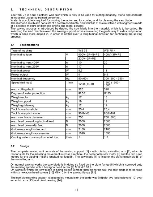
3. T E C H N I C A L D E S C R I P T I O N<br />
Your WS 75 is a full electrical wall saw which is only to be used for cutting masonry, stone and concrete<br />
in industrial usage by trained personnel.<br />
Water is absolutely required for cooling the motor and for cooling and for cleaning the saw blade.<br />
The diamond saw blade consists of a prestressed metal disk which is at its circuit fixed with segments made<br />
of a sintered mixture of diamond grains and metal powder.<br />
The sawing process is introduced by dipping the saw blade into the material, which is to be cutted. By<br />
switching the feed direction over, the sawing support moves now along the guide-way to a desired point on<br />
which is once more dipped in, in order to switch over to longitudinal direction for continuing the sawing<br />
process.<br />
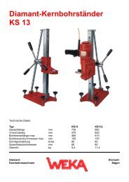
3.1 Specifications<br />
Type of machine WS 75 WS 75 H<br />
Nominal voltage V 400V3P+N+PE 400V3P+PE<br />
14<br />
230V3P+PE<br />
Nominal current 400V A 10 20<br />
Nominal current 230V A 17<br />
Nominal power W 5,5 11<br />
Power output W 4 9,5<br />
Nominal frequency Hz 50 (60) 300 (200 - 350)<br />
Speed (full load) 1/min<br />
1200 (1400)<br />
max. cutting depth mm 320 320<br />
Degree of water protection IP 55 IP 55<br />
Weight-motor kg 17 13<br />
Weight-support kg 19 19<br />
Weight-guide-way kg 12 12<br />
Tool fixture-borehole mm 25,4 25,4<br />
1500 (1200 -<br />
1800)<br />
Tool fixture-pitch circle mm 90/6xM8 90/6xM8<br />
max. saw blade diameter mm 750 750 (800)<br />
max. feed power-longitudinal feed N 2000 2000<br />
max. feed power-dip feed N 2000 2000<br />
Guide-way length-standard mm 2180 2180<br />
Guide-way length-accessories mm 1090 1090<br />
Cooling water consumption in full load l/min 1 1,5<br />
3.2 Design<br />
The complete sawing unit consists of the sawing support [1] - with rotating swivelling arm [2], which is<br />
responsible for the adjusting movement in cross direction - the detachable saw motor [3] and the two Feed<br />
motors for the dipping- [4] and longitudinal feed [5]. The saw blade [7] is fixed on the working spindle [6] of<br />
the swivelling arm.<br />
On normal sawing works the saw blade is in doing so fixed on the plate flange [8] which is screwed onto<br />
the working spindle with a hexagon head screw [9] M12x25 10.9.<br />
On works in which the saw blade is being guided almost flush along the wall the saw blade is to be fixed<br />
with six hexagon head screws [10] M8x10 on the sawing flange [11].<br />
The complete sawing support is assembled movable on the guide-way [15] with two locking levers [12] over<br />
eccentric axis [13] and pivot bearing [14].