Isetta 07 - Isotta 07 cerchi / Isotta Forno - Narvells
Isetta 07 - Isotta 07 cerchi / Isotta Forno - Narvells
Isetta 07 - Isotta 07 cerchi / Isotta Forno - Narvells

Create successful ePaper yourself
Turn your PDF publications into a flip-book with our unique Google optimized e-Paper software.
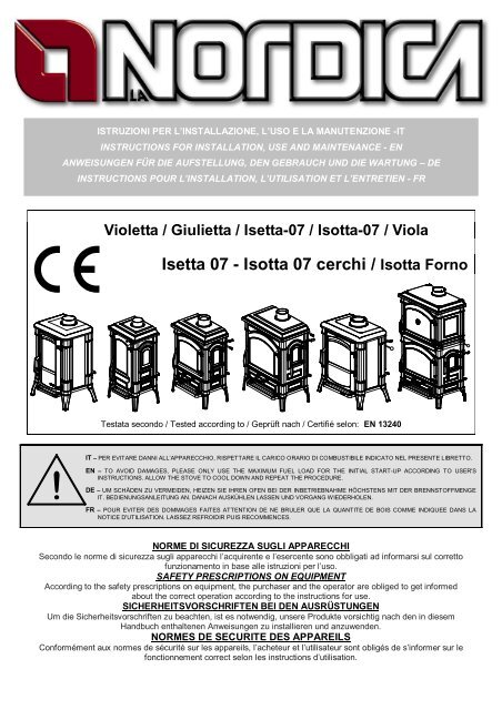
Violetta / Giulietta / <strong>Isetta</strong>-<strong>07</strong> / <strong>Isotta</strong>-<strong>07</strong> / Viola<br />
| <strong>Isetta</strong> <strong>07</strong> - <strong>Isotta</strong> <strong>07</strong> <strong>cerchi</strong> / <strong>Isotta</strong> <strong>Forno</strong><br />
!<br />
ISTRUZIONI PER L’INSTALLAZIONE, L’USO E LA MANUTENZIONE -IT<br />
INSTRUCTIONS FOR INSTALLATION, USE AND MAINTENANCE - EN<br />
ANWEISUNGEN FÜR DIE AUFSTELLUNG, DEN GEBRAUCH UND DIE WARTUNG – DE<br />
INSTRUCTIONS POUR L’INSTALLATION, L’UTILISATION ET L’ENTRETIEN - FR<br />
Testata secondo / Tested according to / Geprüft nach / Certifié selon: EN 13240<br />
IT – PER EVITARE DANNI ALL’APPARECCHIO, RISPETTARE IL CARICO ORARIO DI COMBUSTIBILE INDICATO NEL PRESENTE LIBRETTO.<br />
EN – TO AVOID DAMAGES, PLEASE ONLY USE THE MAXIMUM FUEL LOAD FOR THE INITIAL START-UP ACCORDING TO USER'S<br />
INSTRUCTIONS. ALLOW THE STOVE TO COOL DOWN AND REPEAT THE PROCEDURE.<br />
DE – UM SCHÄDEN ZU VERMEIDEN, HEIZEN SIE IHREN OFEN BEI DER INBETRIEBNAHME HÖCHSTENS MIT DER BRENNSTOFFMENGE<br />
IT. BEDIENUNGSANLEITUNG AN. DANACH AUSKÜHLEN LASSEN UND VORGANG WIEDERHOLEN.<br />
FR – POUR EVITER DES DOMMAGES FAITES ATTENTION DE NE BRULER QUE LA QUANTITE DE BOIS COMME INDIQUEE DANS LA<br />
NOTICE D'UTILISATION. LAISSEZ REFROIDIR PUIS RECOMMENCES.<br />
NORME DI SICUREZZA SUGLI APPARECCHI<br />
Secondo le norme di sicurezza sugli apparecchi l’acquirente e l’esercente sono obbligati ad informarsi sul corretto<br />
funzionamento in base alle istruzioni per l’uso.<br />
SAFETY PRESCRIPTIONS ON EQUIPMENT<br />
According to the safety prescriptions on equipment, the purchaser and the operator are obliged to get informed<br />
about the correct operation according to the instructions for use.<br />
SICHERHEITSVORSCHRIFTEN BEI DEN AUSRÜSTUNGEN<br />
Um die Sicherheitsvorschriften zu beachten, ist es notwendig, unsere Produkte vorsichtig nach den in diesem<br />
Handbuch enthaltenen Anweisungen zu installieren und anzuwenden.<br />
NORMES DE SECURITE DES APPAREILS<br />
Conformément aux normes de sécurité sur les appareils, l’acheteur et l’utilisateur sont obligés de s’informer sur le<br />
fonctionnement correct selon les instructions d’utilisation.
GIULIETTA – ISETTA-<strong>07</strong> – ISOTTA-<strong>07</strong> – ISOTTA FORNO – VIOLA – VIOLETTA<br />
DICHIARAZIONE DI CONFORMITA’ DEL COSTRUTTORE<br />
Oggetto: assenza di amianto e cadmio<br />
Si dichiara che tutti i nostri apparecchi vengono assemblati con materiali che non presentano parti di amianto o suoi<br />
derivati e che nel materiale d’apporto utilizzato per le saldature non è presente/utilizzato in nessuna forma il cadmio,<br />
come previsto dalla norma di riferimento.<br />
Oggetto: Regolamento CE n. 1935/2004<br />
Si dichiara che in tutti gli apparecchi da noi prodotti, i materiali destinati a venire a contatto con i cibi sono adatti<br />
all’uso alimentari, in conformità al Regolamento CE in oggetto.<br />
DECLARATION OF CONFORMITY OF THE MANUFACTURER<br />
Object: Absence of asbestos and cadmium<br />
We declare that the materials used for the assembly of all our appliances are without asbestos parts or asbestos<br />
derivates and that in the material used for welding, cadmium is not present, as prescribed in relevant norm.<br />
Object: CE n. 1935/2004 regulation.<br />
We declare that in all products we produce, the materials which will get in touch with food are suitable for alimentary<br />
use, according to the a.m. CE regulation.<br />
KONFORMITÄTSERKLÄRUNG DES HERSTELLERS<br />
Betreff: Fehlen von Asbest und Kadmium<br />
Wir bestätigen, dass die verwendeten Materialen oder Teilen für die Herstellung der La Nordica Geräte ohne Asbest<br />
und Derivat sind und auch das Lot für das Schweißen immer ohne Kadmium ist.<br />
Betreff: Ordnung CE n. 1935/2004. Wir erklären in alleiniger Verantwortung, dass die Materialien der Teile, die für<br />
den Kontakt mit Lebensmitteln vorgesehen sind, für die Nahrungsbenutzung geeignet sind und der Richtlinien CE n.<br />
1935/2004 erfüllen.<br />
DÉCLARATION DE CONFORMITÉ DU FABRICANT<br />
Objet: absence d'amiante et de cadmium<br />
Nous déclarons que tous nos produits sont assemblés avec des matériaux qui ne présentent pas de parties en<br />
amiante ou ses dérivés et que le matériel d'apport utilisé pour les soudures ne présente/utilise pas de cadmium, sous<br />
aucune forme, comme prévu par la norme de référence.<br />
Objet: Règlement CE n. 1935/2004. Nous déclarons que dans tous nos appareils, les matériaux destinés à entrer en<br />
contact avec les aliments sont aptes à l'usage alimentaire, conformément au Règlement CE en question<br />
2 1195300 Rev.08 – IT – EN – DE – FR
GIULIETTA – ISETTA-<strong>07</strong> – ISOTTA-<strong>07</strong> – ISOTTA FORNO – VIOLA – VIOLETTA<br />
ISOTTA FORNO<br />
PRIMA DELL’INSTALLAZIONE ESEGUIRE LE SEGUENTI VERIFICHE.<br />
BEFORE THE INSTALLATION PERFORM THE FOLLOWING CHECKS.<br />
VOR DER AUFSTELLUNG FOLGENDE PRÜFUNGEN AUSFÜHREN.<br />
AVANT L’INSTALLATION IL FAUT RÉALISER LES SUIVANTES VÉRIFICATIONS.<br />
NON INCLINARE LA STUFA<br />
DO NOT TILT THE STOVE<br />
DEN OFEN NICHT KIPPEN<br />
NE PAS INCLINER LE POÊLE<br />
1195300 Rev.08 – IT – EN – DE – FR 3
GIULIETTA – ISETTA-<strong>07</strong> – ISOTTA-<strong>07</strong> – ISOTTA FORNO – VIOLA – VIOLETTA<br />
INDICE IT<br />
1. DATI TECNICI ................................................................................................................................................... 6<br />
2. DESCRIZIONE TECNICA .................................................................................................................................. 7<br />
3. NORME PER L’INSTALLAZIONE ...................................................................................................................... 7<br />
4. SICUREZZA ANTINCENDIO ............................................................................................................................. 8<br />
4.1. PRONTO INTERVENTO ............................................................................................................................ 9<br />
5. CANNA FUMARIA ............................................................................................................................................. 9<br />
5.1. POSIZIONE DEL COMIGNOLO ................................................................................................................. 9<br />
6. COLLEGAMENTO AL CAMINO ....................................................................................................................... 11<br />
7. AFFLUSSO D’ARIA NEL LUOGO D’INSTALLAZIONE DURANTE LA COMBUSTIONE ................................... 11<br />
8. COMBUSTIBILI AMMESSI / NON AMMESSI ................................................................................................... 11<br />
9. ACCENSIONE ................................................................................................................................................. 12<br />
10. FUNZIONAMENTO NORMALE .................................................................................................................... 13<br />
11. USO DEL FORNO (dove presente) .............................................................................................................. 13<br />
12. FUNZIONAMENTO NEI PERIODI DI TRANSIZIONE ................................................................................... 14<br />
13. MANUTENZIONE E CURA .......................................................................................................................... 14<br />
13.1. PULIZIA CANNA FUMARIA .................................................................................................................. 14<br />
13.2. PULIZIA VETRO................................................................................................................................... 14<br />
13.3. PULIZIA CASSETTO CENERE ............................................................................................................ 14<br />
14. FERMO ESTIVO .......................................................................................................................................... 14<br />
15. COLLEGAMENTO ALLA CANNA FUMARIA DI UN CAMINETTO O FOCOLARE APERTO ......................... 15<br />
15. SCHEDA TECNICA – TECHNICAL DATA SHEETS – TECHNISCHE PROTOKOLLE .................................. 45<br />
INDEX EN<br />
1. TECHNICAL DATA .......................................................................................................................................... 16<br />
2. TECHNICAL DESCRIPTION ............................................................................................................................ 17<br />
3. RULES FOR INSTALLATION........................................................................................................................... 17<br />
4. FIRE SAFETY .................................................................................................................................................. 18<br />
4.1. FIRST-AID MEASURES ........................................................................................................................... 18<br />
5. FLUE ............................................................................................................................................................... 18<br />
5.1. CHIMNEY CAP ........................................................................................................................................ 19<br />
6. CONNECTION TO THE CHIMNEY .................................................................................................................. 20<br />
7. AIR ENTRANCE INTO THE INSTALLATION PLACE DURING COMBUSTION ................................................ 21<br />
8. ADMITTED/NOT ADMITTED FUEL ................................................................................................................. 21<br />
9. LIGHTING ........................................................................................................................................................ 22<br />
10. NORMAL OPERATION ................................................................................................................................ 22<br />
11. USE OF THE OVEN..................................................................................................................................... 23<br />
12. OPERATION IN TRANSITION PERIODS ..................................................................................................... 23<br />
13. MAINTENANCE AND CARE ........................................................................................................................ 23<br />
13.1. CLEANING OF THE FLUE ................................................................................................................... 23<br />
13.2. CLEANING OF THE GLASS ................................................................................................................. 24<br />
13.3. CLEANING OF THE ASH DRAWER ..................................................................................................... 24<br />
14. SUMMER STOP .......................................................................................................................................... 24<br />
15. CONNECTING A CHIMNEY OR OPEN FURNACE TO THE FLUE .............................................................. 24<br />
15. SCHEDA TECNICA – TECHNICAL DATA SHEETS – TECHNISCHE PROTOKOLLE .................................. 45<br />
4 1195300 Rev.08 – IT – EN – DE – FR
GIULIETTA – ISETTA-<strong>07</strong> – ISOTTA-<strong>07</strong> – ISOTTA FORNO – VIOLA – VIOLETTA<br />
INHALTSVERZEICHNIS DE<br />
1. TECHNISCHE ANGABEN................................................................................................................................ 25<br />
2. TECHNISCHE BESCHREIBUNG ..................................................................................................................... 26<br />
3. INSTALLATIONSVORSCHRIFTEN .................................................................................................................. 26<br />
4. BRANDSCHUTZ .............................................................................................................................................. 27<br />
4.1. NOTFALLMASSNAHMEN ........................................................................................................................ 28<br />
5. SCHORNSTEINROHR..................................................................................................................................... 28<br />
5.1. SCHORNSTEIN ....................................................................................................................................... 28<br />
6. KAMINANSCHLUSS ........................................................................................................................................ 30<br />
7. LUFTZUSTROM IN DEN AUFSTELLRAUM WÄHREND DER VERBRENNUNG.............................................. 30<br />
8. ZULÄSSIGE / UNZULÄSSIGE BRENNSTOFFE .............................................................................................. 31<br />
9. ANZÜNDEN ..................................................................................................................................................... 31<br />
10. NORMALBETRIEB....................................................................................................................................... 32<br />
11. BACKEN (wenn anwesend).......................................................................................................................... 33<br />
12. BETRIEB IN DER ÜBERGANGSZEIT .......................................................................................................... 33<br />
13. WARTUNG UND PFLEGE ........................................................................................................................... 33<br />
13.1. Reinigung des Schornsteins ................................................................................................................. 33<br />
13.2. Reinigung des Sichtfensters ................................................................................................................. 33<br />
13.3. Reinigung des Aschekastens ................................................................................................................ 34<br />
14. SOMMERPAUSE ......................................................................................................................................... 34<br />
15. ANSCHLUSS AN DEN RAUCHABZUG EINES OFFENEN KAMINS ............................................................ 34<br />
15. SCHEDA TECNICA – TECHNICAL DATA SHEETS – TECHNISCHE PROTOKOLLE .................................. 45<br />
TABLE DES MATIERES FR<br />
1. DONNÉES TECHNIQUES ............................................................................................................................... 35<br />
2. DESCRIPTION TECHNIQUE ........................................................................................................................... 36<br />
3. NORMES POUR L’INSTALLATION ................................................................................................................. 36<br />
4. SÉCURITÉ ANTI-INCENDIE ............................................................................................................................ 37<br />
4.1. INTERVENTION D'URGENCE ................................................................................................................. 38<br />
5. CONDUIT DE CHEMINEE ............................................................................................................................... 38<br />
5.1. POSITION DU TERMINAL DE CHEMINEE .............................................................................................. 38<br />
6. RACCORDEMENT A LA CHEMINEE............................................................................................................... 40<br />
7. ARRIVÉE D'AIR DANS LE LIEU D'INSTALLATION PENDANT LA COMBUSTION .......................................... 40<br />
8. COMBUSTIBLES ADMIS / NON ADMIS .......................................................................................................... 41<br />
9. ALLUMAGE ..................................................................................................................................................... 41<br />
10. FONCTIONNEMENT NORMAL .................................................................................................................... 42<br />
11. UTILISATION DU FOUR (où présent) .......................................................................................................... 43<br />
12. FONCTIONNEMENT AU COURS DES PÉRIODES DE TRANSITION ......................................................... 43<br />
13. MAINTENANCE ET ENTRETIEN ................................................................................................................. 43<br />
13.1. NETTOYAGE DU TUYAU D'ÉVACUATION DE LA FUMÉE .................................................................. 43<br />
13.2. NETTOYAGE DE LA VITRE ................................................................................................................. 43<br />
13.3. NETTOYAGE DU TIROIR DES CENDRES .......................................................................................... 44<br />
14. REPOS D'ETE ............................................................................................................................................. 44<br />
15. RACCORDEMENT OU D'UN FOYER OUVERT ........................................................................................... 44<br />
15. SCHEDA TECNICA – TECHNICAL DATA SHEETS – TECHNISCHE PROTOKOLLE .................................. 45<br />
1195300 Rev.08 – IT – EN – DE – FR 5
1. DATI TECNICI<br />
Definizione: Stufa-camino secondo EN 13240<br />
GIULIETTA – ISETTA-<strong>07</strong> – ISOTTA-<strong>07</strong> – ISOTTA FORNO – VIOLA – VIOLETTA<br />
VIOLA VIOLETTA GIULIETTA<br />
ISOTTA<br />
FORNO<br />
ISETTA <strong>07</strong> ISOTTA <strong>07</strong><br />
ISETTA <strong>07</strong><br />
con <strong>cerchi</strong><br />
ISOTTA <strong>07</strong><br />
con <strong>cerchi</strong><br />
Sistema costruttivo 1* 1* 1* 1* 1* 1*<br />
Potenza nominale in kW 7 6 6 11,5 7 9<br />
Rendimento in % 78,1 78,3 78,3 83,1 78,1 83<br />
Diametro tubo in mm 150 120 120 150 150 150<br />
Quantità max combustibile –<br />
legna in kg/h<br />
Depressione a rendimento<br />
calorifico nominale in mmH2O<br />
CO misurato al 13% di ossigeno<br />
in %<br />
Emissione gas di scarico in g/s –<br />
legna<br />
Temperatura gas di scarico nel<br />
mezzo in C° - legna<br />
Dimensioni apertura focolare in<br />
mm (L x P)<br />
Dimensioni corpo focolare /<br />
testata focolare in mm (L x H x P)<br />
2,1 1,8 1,8 3,2 2,1 2,5<br />
1,2 1 1,0 1,2 1,2 1,2<br />
0,09 0,11 0,11 0,10 0,09 0,09<br />
6,1 7 7 10,3 6,1 12,31<br />
313 255 253 231 314 190<br />
380 X 245 235 x 280 235x295 519 x 305 380x288 519x371<br />
480x300x220 350x290x225 350x290x250 597x360x290 467x300x293 597x360x350<br />
Tipo di griglia Griglia piana, girevole dall’esterno<br />
Altezza stufa in mm 706 706 706 1244<br />
467x380x293 597x422x350<br />
706 775<br />
760 830<br />
Larghezza stufa in mm 640 495 487 795 660 790<br />
Profondità stufa (con maniglie) in<br />
mm<br />
465 440 430 530<br />
Peso in Kg 154 117 105 296<br />
Distanze di sicurezza<br />
antincendio<br />
Capitolo 4<br />
Accessorio: guanto<br />
* la porta del focolare è a chiusura automatica.<br />
450 520<br />
590 660<br />
150 190<br />
165 210<br />
Il volume di riscaldamento delle stufe secondo EN 13240, per edifici il cui isolamento termico non corrisponde alle<br />
disposizioni sulla protezione del calore, è:<br />
GIULIETTA ISETTA-<strong>07</strong> ISOTTA-<strong>07</strong> <strong>Isotta</strong><br />
VIOLETTA VIOLA FORNO<br />
(30 Kcal/h x m 3 ) - tipo di costruzione favorevole: 172 m³ 200 m³ 258 m³ 330 m³<br />
(40 Kcal/h x m 3 ) - tipo di costruzione meno favorevole: 129 m³ 150 m³ 193 m³ 248 m³<br />
(50 Kcal/h x m 3 ) - tipo di costruzione sfavorevole: 103 m³ 120 m³ 155 m³ 198 m³<br />
Con un isolamento termico adeguato alle disposizioni sulla protezione del calore il volume di riscaldamento è<br />
maggiore. Con un riscaldamento temporaneo, in caso di interruzioni superiori a 8h, la capacità di riscaldamento<br />
diminuisce del 25% circa.<br />
6 1195300 Rev.08 – IT
GIULIETTA – ISETTA-<strong>07</strong> – ISOTTA-<strong>07</strong> – ISOTTA FORNO – VIOLA – VIOLETTA<br />
2. DESCRIZIONE TECNICA<br />
Le stufe camino La Nordica si addicono a riscaldare spazi abitativi per alcuni periodi, o a sostenere un riscaldamento<br />
centralizzato insufficiente. Esse sono ideali per appartamenti di vacanza e case del fine settimana oppure come<br />
riscaldamento ausiliario durante tutto l’anno. Come combustibili vengono utilizzati ceppi di legna.<br />
La stufa-camino è costituita da fusioni di ghisa grezza e smaltata e da lastre in lamiera d’acciaio. Il focolare è<br />
internamente rivestito di singole lastre in ghisa ed è dotato di una griglia girevole estraibile. Il modello GIULIETTA è<br />
provvisto di una parete interna estraibile. Grazie a dei fori calibrati, praticati su quest’ultima, viene garantito un<br />
apporto di aria pre-riscaldata all’interno del focolare, ottenendo così una post-combustione che aumenta il rendimento<br />
e riduce le emissioni dei gas incombusti .<br />
Il focolare è dotato di una porta panoramica con vetro ceramico (resistente fino a 700°C). Questo cons ente<br />
un’affascinante vista delle fiamme ardenti ed impedisce ogni possibile fuoriuscita di scintille e fumo.<br />
Il riscaldamento dell’ambiente avviene:<br />
per irraggiamento: attraverso il vetro panoramico e le<br />
superfici esterne calde della stufa.<br />
La stufa-camino è dotata di registri aria primaria e<br />
secondaria, per mezzo dei quali viene regolata l’aria per la<br />
combustione.<br />
Registro d’aria PRIMARIA<br />
(termostato B Figura 2) (valvola B1 Figura 1)<br />
Con il termostato (<strong>Isetta</strong>-<strong>07</strong>, <strong>Isotta</strong>-<strong>07</strong>) o valvola (Giulietta),<br />
situati posteriormente sul lato destro della stufa, viene<br />
regolato il passaggio d’aria attraverso il cassetto cenere e<br />
la griglia in direzione del combustibile. L’aria primaria è<br />
necessaria per il processo di combustione. Il cassetto<br />
cenere deve essere svuotato regolarmente in modo che la<br />
cenere non possa ostacolare l’entrata d’aria primaria.<br />
Attraverso l’aria primaria viene anche mantenuto vivo il<br />
fuoco.<br />
Durante la combustione di legna, il registro aria primaria<br />
deve essere aperto solo un poco, altrimenti la legna arde<br />
troppo e la stufa si può surriscaldare. Per la disposizione<br />
corretta vedere tabella al paragrafo 10.<br />
Registro aria SECONDARIA<br />
(A Figura 2) (A1 Figura 1)<br />
Sopra la porta del focolare si trova il registro aria<br />
secondaria. Questa valvola deve essere aperta (quindi<br />
spostata verso destra) in particolare per la combustione di<br />
legna, in modo che il carbonio incombusto possa subire<br />
una post-combustione. Vedi paragrafo 10. Attraverso<br />
questo registro è possibile regolare l’andamento della<br />
Stufa. Lasciandolo leggermente aperto, a seconda del<br />
tiraggio del camino, è possibile mantenere il vetro pulito.<br />
Registro di accensione (C Figura 2) vedere paragrafo 9<br />
3. NORME PER L’INSTALLAZIONE<br />
La stufa è assemblata e pronta per l’allacciamento e deve<br />
essere collegata mediante un raccordo all’esistente canna<br />
fumaria della casa. Il raccordo deve essere possibilmente<br />
corto, rettilineo, orizzontale o posizionato leggermente in<br />
salita. I collegamenti devono essere a tenuta stagna.<br />
Figura 1<br />
Figura 2<br />
E’ obbligatorio rispettare norme nazionali ed europee, disposizioni locali o in materia di legislazione edilizia,<br />
nonché regolamentazioni antincendio. Pertanto vi consigliamo di informarvi preventivamente presso il Vs. capo<br />
spazzacamino distrettuale.<br />
Bisogna inoltre verificare il sufficiente afflusso d’aria necessario alla combustione, a tale proposito è fondamentale<br />
prestare attenzione a finestre e porte con chiusura stagna (guarnizioni di tenuta).<br />
1195300 Rev.08 – IT 7<br />
A<br />
A1<br />
Scuoti<br />
griglia<br />
GIULIETTA – VIOLETTA<br />
ISETTA <strong>07</strong> – ISOTTA <strong>07</strong> – VIOLA C<br />
<strong>Isotta</strong> FORNO<br />
B<br />
B1<br />
Scuoti griglia
GIULIETTA – ISETTA-<strong>07</strong> – ISOTTA-<strong>07</strong> – ISOTTA FORNO – VIOLA – VIOLETTA<br />
Non è consentito il collegamento di più apparecchi allo stesso camino. Il diametro dell’apertura della canna fumaria<br />
per il collegamento deve corrispondere per lo meno al diametro del tubo fumo.<br />
L’apertura dovrebbe essere dotata di una connessione a muro per la ricezione del tubo di scarico e di un rosone.<br />
Prima dell’installazione verificare se la portata della sottostruttura regge il peso del vostro apparecchio. In caso di<br />
portata insufficiente è necessario adottare opportune misure (ad es. piastra per la distribuzione del peso) per<br />
raggiungere la stessa.<br />
La NORDICA S.p.A. non è responsabile del prodotto modificato senza autorizzazione e tanto meno per l’uso<br />
di ricambi non originali.<br />
I FOCOLARI NON DEVONO ESSERE MODIFICATI !<br />
4. SICUREZZA ANTINCENDIO<br />
Nell’installazione della stufa devono essere osservate le seguenti misure di sicurezza:<br />
a) al fine di assicurare un sufficiente isolamento termico, rispettare la distanza minima di sicurezza dal retro e da<br />
entrambi i lati da elementi costruttivi ed oggetti infiammabili e sensibili al calore (mobili, rivestimenti di legno,<br />
stoffe ecc.) (Figura 3 A). Tutte le distanze minime di sicurezza sono indicate sulla targhetta tecnica del<br />
prodotto e NON si deve scendere al di sotto dei valori indicati;<br />
b) davanti alla stufa-camino non deve esserci alcun oggetto o materiale di costruzione infiammabile e sensibile al<br />
calore a meno di 100 cm di distanza; Tale distanza può essere ridotta a 40 cm qualora venga installata una<br />
protezione, retroventilata e resistente al calore, davanti all’intero componente da proteggere.<br />
c) qualora il prodotto venga installato su un pavimento di materiale infiammabile, bisogna prevedere un sottofondo<br />
ignifugo, per esempio una pedana d'acciaio (dimensioni secondo l’ordinamento regionale). Il sottofondo deve<br />
sporgere frontalmente di almeno 50 cm e lateralmente di almeno altri 30 cm oltre all’apertura della porta di carico<br />
(Figura 3 B).<br />
d) sopra al prodotto non devono essere presenti componenti infiammabili (es. mobili - pensili).<br />
100<br />
A B<br />
Figura 3<br />
La stufa-camino deve funzionare esclusivamente con il cassetto cenere inserito. I residui solidi della combustione<br />
(ceneri) devono essere raccolti in un contenitore ermetico e resistente al fuoco. La stufa non deve mai essere accesa<br />
in presenza di emissioni gassose o vapori (per esempio colla per linoleum, benzina ecc.). Non depositate materiali<br />
infiammabili nelle vicinanze della stufa.<br />
Durante la combustione viene sprigionata energia termica che comporta un marcato riscaldamento delle superfici,<br />
della porta e del vetro del focolare, delle maniglie delle porte o di comando, del tubo fumi ed eventualmente della<br />
parte anteriore dell’apparecchio. Evitate il contatto con tali elementi senza un corrispondente abbigliamento protettivo<br />
o senza utensili accessori (guanti resistenti al calore, dispositivi di comando).<br />
Fate in modo che i bambini siano consapevoli di questi pericoli e teneteli lontani dal focolare durante il suo<br />
funzionamento.<br />
Quando si utilizza un combustibile errato o troppo umido si potrebbero formare dei depositi (creosoto) nella canna<br />
fumaria con possibile incendio della canna fumaria stessa.<br />
8 1195300 Rev.08 – IT<br />
30<br />
50<br />
30
GIULIETTA – ISETTA-<strong>07</strong> – ISOTTA-<strong>07</strong> – ISOTTA FORNO – VIOLA – VIOLETTA<br />
4.1. PRONTO INTERVENTO<br />
Se si manifesta un incendio nel collegamento o nella canna fumaria :<br />
a) Chiudere la porta di caricamento e del cassetto cenere.<br />
b) Chiudere i registri dell’aria comburente<br />
c) Spegnere tramite l’uso di estintori ad anidride carbonica ( CO2 a polveri )<br />
d) Richiedere l’immediato intervento dei Vigili del Fuoco<br />
NON SPEGNERE IL FUOCO CON L’USO DI GETTI D’ACQUA.<br />
Quando la canna fumaria smette di bruciare, farla verificare da uno specialista per individuare eventuali crepe o punti<br />
permeabili.<br />
5. CANNA FUMARIA<br />
Requisiti fondamentali per un corretto funzionamento<br />
dell’apparecchio:<br />
• la sezione interna deve essere preferibilmente<br />
circolare;<br />
• essere termicamente isolata ed impermeabile e<br />
costruita con materiali idonei a resistere al calore, ai<br />
prodotti della combustione ed alle eventuali condense;<br />
• essere priva di strozzature ed avere andamento<br />
verticale con deviazioni non superiori a 45°;<br />
• se già usata deve essere pulita;<br />
• rispettare i dati tecnici del manuale di istruzioni;<br />
Qualora le canne fumarie fossero a sezione quadrata o<br />
rettangolare gli spigoli interni devono essere arrotondati con<br />
raggio non inferiore a 20 mm. Per la sezione rettangolare il<br />
rapporto massimo tra i lati deve essere ≤ 1,5.<br />
Una sezione troppo piccola provoca una diminuzione del<br />
tiraggio. Si consiglia un’altezza minima di 4 m.<br />
Sono vietate e pertanto pregiudicano il buon funzionamento<br />
dell’apparecchio: fibrocemento, acciaio zincato, superfici<br />
interne ruvide e porose. In Figura 4 sono riportati alcuni esempi<br />
di soluzione.<br />
La sezione minima deve essere di 4 dm 2 (per esempio<br />
20x20cm) per gli apparecchi il cui diametro di condotto è<br />
inferiore a 200mm, o 6,25dm 2 (per esempio 25x25cm) per<br />
gli apparecchi con diametro superiore a 200mm.<br />
Il tiraggio creato dalla vostra canna fumaria deve essere<br />
sufficiente ma non eccessivo.<br />
Una sezione della canna fumaria troppo importante può<br />
presentare un volume troppo grande da riscaldare e dunque<br />
provocare delle difficoltà di funzionamento dell’apparecchio; per<br />
evitare ciò provvedete ad intubare la stessa per tutta la sua altezza. Una sezione troppo piccola provoca una<br />
diminuzione del tiraggio.<br />
La canna fumaria deve essere adeguatamente distanziata da materiali infiammabili o combustibili mediante<br />
un opportuno isolamento o un’intercapedine d’aria.<br />
E’ vietato far transitare all’interno della stessa tubazioni di impianti o canali di adduzione d’aria. E’ proibito inoltre<br />
praticare aperture mobili o fisse, sulla stessa, per il collegamento di ulteriori apparecchi diversi.<br />
5.1. POSIZIONE DEL COMIGNOLO<br />
(1) (2)<br />
(1) Canna fumaria in acciaio AISI 316 con doppia<br />
camera isolata con materiale resistente a<br />
400°C. Efficienza 100% ottima.<br />
(2) Canna fumaria in refrattario con doppia<br />
camera isolata e rivestimento esterno in<br />
calcestruzzo alleggerito. Efficienza 100%<br />
ottima.<br />
(3) Canna fumaria tradizionale in argilla sezione<br />
quadrata con intercapedini. Efficienza 80%<br />
ottima.<br />
(4) Evitare canne fumarie con sezione<br />
rettangolare interna il cui rapporto sia diverso<br />
dal disegno. Efficienza 40% mediocre.<br />
Figura 4<br />
Il tiraggio della canna fumaria dipende anche dall’idoneità del comignolo.<br />
È pertanto indispensabile che, se costruito artigianalmente, la sezione di uscita sia più di due volte la sezione interna<br />
della canna fumaria.<br />
Dovendo sempre superare il colmo del tetto, il comignolo dovrà assicurare lo scarico anche in presenza di vento<br />
(Figura 5).<br />
Il comignolo deve rispondere ai seguenti requisiti:<br />
• avere sezione interna equivalente a quella del camino.<br />
• avere sezione utile d’uscita doppia di quella interna della canna fumaria.<br />
1195300 Rev.08 – IT 9<br />
(3)<br />
(4)<br />
Max.<br />
A+1/2A<br />
A+1/2A<br />
A
GIULIETTA – ISETTA-<strong>07</strong> – ISOTTA-<strong>07</strong> – ISOTTA FORNO – VIOLA – VIOLETTA<br />
• essere costruito in modo da impedire la penetrazione nella canna fumaria di pioggia, neve e di qualsiasi<br />
corpo estraneo.<br />
• essere facilmente ispezionabile, per eventuali operazioni di manutenzione e pulizia.<br />
Inclinazione del tetto<br />
COMIGNOLI DISTANZE E POSIZIONAMENTO UNI 10683/98<br />
Distanza tra il colmo e il<br />
camino<br />
10 1195300 Rev.08 – IT<br />
Figura 5<br />
Figura 6<br />
Figura 7<br />
Altezza minima del camino (misurata dallo<br />
sbocco)<br />
α A (m) H (m)<br />
15°<br />
30°<br />
45°<br />
60°<br />
(1) Comignolo industriale<br />
ad elementi prefabbricati,<br />
consente un ottimo<br />
smaltimento dei fumi.<br />
50 cm (1) In caso di canne fumarie affiancate un comignolo dovrà<br />
sovrastare l’altro d’almeno 50 cm al fine d’evitare trasferimenti<br />
di pressione tra le canne stesse.<br />
2 m 10 m<br />
1<br />
m<br />
(2) Comignolo artigianale.<br />
La giusta sezione di uscita<br />
deve essere minimo 2 volte<br />
la sezione interna della<br />
canna fumaria, ideale 2,5<br />
volte.<br />
(1) Il comignolo non deve avere ostacoli entro i 10 m da muri,<br />
falde ed alberi. In caso contrario innalzare lo stesso d’almeno<br />
1 m sopra l’ostacolo.<br />
Il comignolo deve oltrepassare il colmo del tetto d’almeno 1 m.<br />
< 1,85 m 0,50 m oltre il colmo<br />
> 1,85 m 1,00 m dal tetto<br />
< 1,50 m 0,50 m oltre il colmo<br />
> 1,50 m 1,30 m dal tetto<br />
< 1,30 m 0,50 m oltre il colmo<br />
> 1,30 m 2,00 m dal tetto<br />
< 1,20 m 0,50 m oltre il colmo<br />
> 1,20 m 2,60 m dal tetto<br />
(3) Comignolo per<br />
canna fumaria in<br />
acciaio deflettore dei<br />
fumi a forma di cono.
GIULIETTA – ISETTA-<strong>07</strong> – ISOTTA-<strong>07</strong> – ISOTTA FORNO – VIOLA – VIOLETTA<br />
H min.<br />
6. COLLEGAMENTO AL CAMINO<br />
La stufa-camino è dotata di scarico fumi superiore e posteriore a pag. 50 è rappresentato il montaggio dei particolari.<br />
Il tubo di congiunzione per il collegamento al camino deve essere più corto possibile ed i punti d’unione dei singoli<br />
tubi devono essere ermetici. Il collegamento al camino deve essere eseguito con tubi stabili e robusti (Vi consigliamo<br />
uno spessore di 2 mm). Il tubo di scarico fumi deve essere fissato ermeticamente al camino. Il diametro interno del<br />
tubo di collegamento deve corrispondere al diametro esterno del tronchetto di scarico fumi della stufa. Ciò viene<br />
garantito dai tubi secondo DIN 1298.<br />
ATTENZIONE: qualora il collegamento attraversi particolari composti da materiali infiammabili, nel raggio di 20cm<br />
attorno al tubo tutti i materiali infiammabili devono essere sostituiti da materiali ignifughi e resistenti al calore.<br />
Per un buon funzionamento dell’apparecchio è essenziale che nel luogo d’installazione venga immessa sufficiente<br />
aria per la combustione. Ciò significa che, attraverso apposite aperture, deve poter circolare aria per la combustione<br />
anche a porte e finestre chiuse (vedi paragrafo 7).<br />
La depressione al camino dovrebbe essere di 12 Pa (=1.2 mm di colonna d’acqua). La misurazione deve essere fatta<br />
sempre ad apparecchio caldo (resa calorifica nominale). Quando la depressione supera i 17 PA (1,7 mm di colonna<br />
d’acqua) è necessario ridurre la stessa con l’installazione di un regolatore di tiraggio supplementare (valvola a<br />
farfalla) sul tubo di scarico o nel camino.<br />
7. AFFLUSSO D’ARIA NEL LUOGO D’INSTALLAZIONE DURANTE LA COMBUSTIONE<br />
Poiché le stufe ricavano la loro aria di combustione dal locale di installazione, è essenziale che nel luogo stesso<br />
venga immessa una sufficiente quantità d’aria. In caso di finestre e porte a tenuta stagna (es .case costruite con il<br />
criterio di risparmio energetico) è possibile che l’ingresso di aria fresca non venga più garantito e questo compromette<br />
il tiraggio dell’apparecchio, il vostro benessere e la vostra sicurezza. Bisogna pertanto garantire una alimentazione<br />
aggiuntiva di aria fresca mediante una presa d’aria esterna posta nelle vicinanze dell’apparecchio oppure tramite la<br />
posa di una conduttura per l’aria di combustione che porti verso l’esterno od in un vicino locale areato, ad eccezione<br />
del locale caldaia o garage (VIETATO).<br />
Il tubo di collegamento deve essere liscio con un diametro minimo di 120 mm, deve avere una lunghezza massima di<br />
4 m e presentare non più di tre curve. Qualora questo sia collegato direttamente con l’esterno deve essere dotato di<br />
un apposito frangivento.<br />
L’entrata d’aria per la combustione nel luogo d’installazione non deve essere ostruita durante il funzionamento della<br />
stufa. E’ assolutamente necessario che negli ambienti, in cui vengono fatte funzionare stufe con un tiraggio naturale<br />
del camino, venga immessa tanta aria quanta ne è necessaria per la combustione, ossia fino a 20 m 3 /h. Il naturale<br />
riciclo d’aria deve essere garantito da alcune aperture fisse sull’esterno. La grandezza delle necessarie aperture per<br />
l’aria è fissata dalle relative prescrizioni. Chiedete informazioni al Vostro spazzacamino di fiducia. Le aperture<br />
dovrebbero essere protette con delle griglie e non dovrebbero mai essere otturate.<br />
Una cappa di estrazione (aspirante) installata nella stessa stanza od in una confinante provoca depressione<br />
nell’ambiente. Questo porta alla fuoriuscita di gas combusti (fumo denso, odore); é dunque necessario assicurare un<br />
maggiore afflusso di aria fresca.<br />
La depressione di una cappa aspirante può, nella peggiore delle ipotesi, trasformare la canna fumaria della<br />
stufa in presa d’aria esterna risucchiando i fumi nell’ambiente con conseguenze gravissime per le persone.<br />
8. COMBUSTIBILI AMMESSI / NON AMMESSI<br />
α<br />
>A<br />
><br />
_ A<br />
(1)Asse colmo<br />
(2)Tetto<br />
Figura 8<br />
I combustibili ammessi sono ceppi di legna da ardere. Si devono utilizzare esclusivamente ceppi di legna secca<br />
(contenuto d’acqua max 20%). Si dovrebbero caricare al massimo 2 o 3 ceppi di legna per volta o 4-5 pezzi di lignite.<br />
I pezzi di legna dovrebbero avere una lunghezza di ca. 30 – 40 cm ed una circonferenza di massimo 30 – 35 cm.<br />
La legna usata come combustibile deve avere un contenuto d’umidità inferiore al 20% e la si ottiene con un tempo di<br />
essiccazione di almeno un anno (legno tenero) o di due anni (legno duro) collocandola in un luogo asciutto e ventilato<br />
(per esempio sotto una tettoia). La legna umida rende l’accensione più difficile, poiché è necessaria una maggiore<br />
quantità d’energia per far evaporare l’acqua presente. Il contenuto umido ha inoltre lo svantaggio, con l’abbassarsi<br />
1195300 Rev.08 – IT 11<br />
0,5 m
GIULIETTA – ISETTA-<strong>07</strong> – ISOTTA-<strong>07</strong> – ISOTTA FORNO – VIOLA – VIOLETTA<br />
della temperatura, di far condensare l’acqua prima nel focolare e quindi nel camino. La legna fresca contiene circa il<br />
60% di H2O, perciò non è adatta ad essere bruciata.<br />
Tra gli altri non possono essere bruciati: resti di carbone, ritagli, cascami di corteccia e pannelli, legna umida<br />
o trattata con vernici, materiali di plastica; in tal caso decade la garanzia sull’apparecchio.<br />
Carta e cartone devono essere utilizzati solo per l’accensione. La combustione di rifiuti è VIETATA e<br />
danneggerebbe inoltre la stufa e la canna fumaria, provocando inoltre danni alla salute ed in virtù del disturbo olfattivo<br />
a reclami da parte del vicinato.<br />
La legna non è un combustibile a lunga durata e pertanto non è possibile un riscaldamento continuo della stufa<br />
durante la notte.<br />
Specie Kg/mc KWh/Kg Umidità 20%<br />
Faggio 750 4,0<br />
Cerro 900 4,2<br />
Olmo 640 4,1<br />
Pioppo 470 4,1<br />
Larice * 660 4,4<br />
Abete rosso * 450 4,5<br />
Pino silvestre * 550 4,4<br />
* LEGNI RESINOSI POCO ADATTI PER UNA STUFA<br />
ATTENZIONE: l’uso continuo e prolungato di legna particolarmente ricca di oli aromatici (p.e. Eucalipto, Mirto, etc.)<br />
provoca il deterioramento (sfaldamento) repentino dei componenti in ghisa che compongono il prodotto.<br />
9. ACCENSIONE<br />
IMPORTANTE: alla prima accensione è inevitabile che venga prodotto un odore sgradevole (dovuto all’essiccamento<br />
dei collanti nella cordicella di guarnizione o delle vernici protettive), che sparisce dopo un breve utilizzo. Deve<br />
comunque essere assicurata una buona ventilazione dell’ambiente. Alla prima accensione Vi consigliamo di<br />
caricare una quantità ridotta di combustibile e di aumentare lentamente la resa calorifica dell’apparecchio.<br />
Per effettuare una corretta prima accensione dei prodotti trattati con vernici per alte temperature, occorre sapere<br />
quanto segue:<br />
i materiali di costruzione dei prodotti in questione non sono omogenei, infatti vengono utilizzate parti in ghisa e in<br />
acciaio.<br />
la temperatura alla quale il corpo del prodotto è sottoposto non è omogenea: da zona a zona si registrano<br />
temperature variabili dai 300°C ai 500°C;<br />
durante la sua vita, il prodotto è sottoposto a cicli alternati di accensioni e di spegnimento durante la stessa<br />
giornata e a cicli di intenso utilizzo o di assoluto riposo al variare delle stagioni;<br />
la stufa nuova, prima di potersi definire rodata, dovrà essere sottoposta a diversi cicli di avviamento per poter<br />
consentire a tutti i materiali ed alla vernice di completare le varie sollecitazioni elastiche;<br />
in particolare inizialmente si potrà notare l’emissione di odori tipici dei metalli sottoposti a grande sollecitazione<br />
termica e di vernice ancora fresca. Tale vernice, sebbene in fase di costruzione venga cotta a 250 °C per<br />
qualche ora, dovrà superare più volte e per una certa durata la temperatura di 350°C, prima di incorpo rarsi<br />
perfettamente con le superfici metalliche.<br />
Diventa quindi importante seguire questi piccoli accorgimenti in fase di accensione:<br />
1. Assicuratevi che sia garantito un forte ricambio d'aria nel luogo dove è installato l'apparecchio.<br />
2. Nelle prime accensioni, caricare non eccessivamente la camera di combustione (circa metà della quantità<br />
indicata nel manuale d'istruzioni) e tenere il prodotto acceso per almeno 6-10 ore di continuo, con i registri<br />
meno aperti di quanto indicato nel manuale d'istruzioni.<br />
3. Ripetere questa operazione per almeno 4-5 volte o più, secondo la Vostra disponibilità.<br />
4. Successivamente caricare sempre più ( seguendo comunque quanto descritto sul libretto di istruzione<br />
relativamente al massimo carico) e tenere possibilmente lunghi i periodi di accensione evitando, almeno in<br />
questa fase iniziale, cicli di accensione-spegnimento di breve durata.<br />
5. Durante le prime accessioni nessun oggetto dovrebbe essere appoggiato sulla stufa ed in particolare<br />
sulle superfici laccate. Le superfici laccate non devono essere toccate durante il riscaldamento.<br />
6. Una volta superato il "rodaggio" si potrà utilizzare il prodotto come il motore di un’auto, evitando bruschi<br />
riscaldamenti con eccessivi carichi.<br />
12 1195300 Rev.08 – IT
GIULIETTA – ISETTA-<strong>07</strong> – ISOTTA-<strong>07</strong> – ISOTTA FORNO – VIOLA – VIOLETTA<br />
Per accendere il fuoco consigliamo di usare piccoli listelli di legno con carta oppure altri mezzi di accensione in<br />
commercio, ESCLUSE tutte le sostanze liquide come per es. alcool, benzina, petrolio e simili.<br />
Funzionamento con legna:<br />
Aprire il registro aria secondaria (A , A1), aprire il termostato (B , B1), aprire il registro di tiraggio diretto (C),<br />
accendere il fuoco.<br />
Dopo circa 10 minuti , quando il fuoco è avviato, chiudere il termostato (B , B1) e il registro tiraggio (C) e regolare<br />
l’andatura con il registro (A , A1)<br />
Le aperture per l’aria (primaria e secondaria) devono essere aperte contemporaneamente solo un po' (si deve aprire<br />
anche l’eventuale valvola a farfalla posta sul tubo di scarico fumi). Quando la legna comincia ad ardere regolare l’aria<br />
per la combustione secondo le indicazioni del paragrafo 10.<br />
Mai sovraccaricare la stufa (confrontate la tabella tecnica – quantità max. di combustibile caricabile).<br />
Troppo combustibile e troppa aria per la combustione possono causare surriscaldamento e quindi<br />
danneggiare la stufa, in particolare si potrebbero verificare delle rotture sulla parte inferiore della facciata. La<br />
garanzia non copre i danni dovuti al surriscaldamento dell’apparecchio.<br />
10. FUNZIONAMENTO NORMALE<br />
IMPORTANTE: poiché la porta del focolare ha dimensioni notevoli, vi consigliamo di aprire la porta molto lentamente<br />
per evitare l’uscita di fumi. Per motivi di sicurezza la porta del focolare può essere aperta solo durante il<br />
caricamento di combustibile. Il focolare deve rimanere chiuso durante il funzionamento ed i periodi di nonutilizzo.<br />
Prima di aprire la porta del focolare, aprire il registro di tiraggio diretto (C), caricare il combustibile, chiudere la porta, e<br />
dopo circa 5 o 10 minuti il registro (C).<br />
Con i registri posti sulla facciata della stufa-camino viene regolata l’emissione di calore della stufa. Essi devono<br />
essere aperti secondo il bisogno calorifico. La migliore combustione (con emissioni minime) viene raggiunta quando,<br />
caricando legna, la maggior parte dell’aria per la combustione passa attraverso il registro d’aria secondaria.<br />
Non si deve mai sovraccaricare la stufa (vedi quantità max nella tabella sottostante).<br />
Troppo combustibile e troppa aria per la combustione possono causare surriscaldamento e quindi<br />
danneggiare la stufa, in particolare si potrebbero verificare delle rotture sulla parte inferiore della facciata. La<br />
garanzia non copre i danni dovuti al surriscaldamento dell’apparecchio.<br />
Bisogna pertanto usare la stufa sempre con la porta chiusa per evitare l’effetto forgia.<br />
La regolazione dei registri necessaria per l’ottenimento della resa calorifica nominale con una depressione al camino<br />
è la seguente:<br />
Carica oraria Aria Secondaria (A) Termostato (B) Aria Terziaria<br />
GIULIETTA 1.8 kg/h APERTO (A1) CHIUSO Valvola (B1) Pretarata<br />
ISETTA-<strong>07</strong> 2.1 kg/h APERTO APERTO 5 mm /<br />
ISOTTA-<strong>07</strong> 2.5 kg/h APERTO APERTO 5 mm /<br />
ISOTTA -<strong>07</strong> FORNO 3.2 kg/h APERTO APERTO 5 mm<br />
VIOLA 2.1 kg/h APERTO APERTO /<br />
VIOLETTA 1.8 kg/h APERTO APERTO Pretarata<br />
Oltre che dalla regolazione dell’aria per la combustione, l’intensità della combustione e quindi la resa calorifica della<br />
Vostra stufa è influenzata dal camino. Un buon tiraggio del camino richiede una regolazione più ridotta dell’aria per la<br />
combustione, mentre uno scarso tiraggio necessita maggiormente di un’esatta regolazione dell’aria per la<br />
combustione.<br />
Per verificare la buona combustione della stufa, controllate se il fumo che esce dal camino è trasparente. Se è bianco<br />
significa che la stufa non è regolata correttamente o la legna è troppo bagnata; se invece il fumo è grigio o nero è<br />
segno che la combustione non è completa (è necessaria una maggior quantità di aria secondaria).<br />
11. USO DEL FORNO (dove presente)<br />
Dopo aver pulito la griglia, caricate del combustibile. Grazie all’apporto d’aria per la combustione la<br />
temperatura del forno può essere sensibilmente influenzata. Un sufficiente tiraggio al camino e dei canali<br />
ben puliti per il flusso dei fumi roventi attorno al forno sono fondamentali per un buon risultato di cottura.<br />
La padella forno può essere collocata su diversi piani. Torte spesse e arrosti grandi sono da inserire al<br />
livello più basso. Torte piatte e biscotti vanno al livello medio. Il livello superiore può essere utilizzato per<br />
riscaldare o rosolare.<br />
1195300 Rev.08 – IT 13
12. FUNZIONAMENTO NEI PERIODI DI TRANSIZIONE<br />
GIULIETTA – ISETTA-<strong>07</strong> – ISOTTA-<strong>07</strong> – ISOTTA FORNO – VIOLA – VIOLETTA<br />
Durante il periodo di transizione, ovvero quando le temperature esterne sono più elevate, in caso di improvviso<br />
aumento della temperatura si possono avere dei disturbi alla canna fumaria che fanno si che i gas combusti non<br />
vengono aspirati completamente. I gas di scarico non fuoriescono più completamente (odore intenso di gas).<br />
In tal caso scuotete più frequentemente la griglia e aumentate l’aria per la combustione. Caricate in seguito una<br />
quantità ridotta di combustibile facendo sì che questo bruci più rapidamente (con sviluppo di fiamme) e si stabilizzi<br />
così il tiraggio della canna fumaria. Controllate quindi che tutte le aperture per la pulizia e i collegamenti al camino<br />
siano ermetici. In caso di incertezza rinunciate all’utilizzo della stufa.<br />
13. MANUTENZIONE E CURA<br />
Fate controllare dal Vostro spazzacamino responsabile di zona la regolare installazione della stufa, il collegamento al<br />
camino e l’aerazione.<br />
Per la pulizia delle parti smaltate usare acqua saponata o detergenti non abrasivi o chimicamente non aggressivi.<br />
IMPORTANTE : si possono usare esclusivamente parti di ricambio espressamente autorizzate ed offerte da La<br />
Nordica. In caso di bisogno Vi preghiamo di rivolgerVi al Vs rivenditore specializzato.<br />
L’ APPARECCHIO NON PUÒ ESSERE MODIFICATO!<br />
13.1. PULIZIA CANNA FUMARIA<br />
La corretta procedura di accensione, l’utilizzo di quantità e tipi di combustibili idonei, il corretto posizionamento del<br />
registro dell’aria secondaria, il sufficiente tiraggio del camino e la presenza d’aria comburente sono indispensabili per<br />
il funzionamento ottimale dell’apparecchio. Almeno una volta l’anno è consigliabile eseguire una pulizia completa, o<br />
qualora sia necessario (problemi di malfunzionamento con scarsa resa). Questa operazione, fatta esclusivamente a<br />
stufa fredda, dovrebbe essere svolta da uno spazzacamino che contemporaneamente può effettuare un’ispezione.<br />
Durante la pulizia bisogna togliere dalla stufa il cassetto cenere ed il tubo fumi.<br />
Si può pulire il vano di raccolta fumi dal focolare e, dopo aver tolto il tubo fumi, anche dal tronchetto di scarico con<br />
l’aiuto di una spazzola e di un aspiratore.<br />
Fate attenzione che dopo la pulizia tutte le parti smontate vengano reinstallate in modo ermetico.<br />
13.2. PULIZIA VETRO<br />
Tramite uno specifico ingresso dell’aria secondaria la formazione di deposito di sporco, sul vetro della porta, viene<br />
efficacemente rallentata. Non può comunque mai essere evitata con l’utilizzo dei combustibili solidi (es. legna umida )<br />
e questo non è da considerarsi come un difetto dell’apparecchio .<br />
IMPORTANTE: la pulizia del vetro panoramico deve essere eseguita solo ed esclusivamente a stufa fredda<br />
per evitare l’esplosione. Non usare comunque panni, prodotti abrasivi o chimicamente aggressivi.<br />
ROTTURA DEI VETRI: i vetri essendo in vetroceramica resistenti fino ad uno sbalzo termico di 750°C, no n<br />
sono soggetti a shock termici. La loro rottura può essere causata solo da shock meccanici (urti o chiusura<br />
violenta della porta ecc.). Pertanto la sostituzione non è in garanzia .<br />
13.3. PULIZIA CASSETTO CENERE<br />
Tutte le stufe La NORDICA sono dotate di una griglia focolare e di un cassetto per la raccolta delle ceneri.<br />
Vi consigliamo di svuotare periodicamente il cassetto cenere e di evitarne il riempimento totale, per non surriscaldare<br />
la griglia. Inoltre Vi consigliamo di lasciare sempre 3-4 cm di cenere nel focolare.<br />
ATTENZIONE: le ceneri tolte dal focolare vanno riposte in un recipiente di materiale ignifugo dotato di un coperchio<br />
stagno.<br />
Il recipiente va posto su di un pavimento ignifugo, lontano da materiali infiammabili fino allo spegnimento e<br />
raffreddamento completo.<br />
14. FERMO ESTIVO<br />
Dopo aver effettuato la pulizia del focolare, del camino e della canna fumaria, provvedendo all’eliminazione totale<br />
della cenere ed altri eventuali residui, è opportuno chiudere tutte le porte con i relativi registri focolare. Nel caso in cui<br />
l’apparecchio venga disconnesso dal camino, è opportuno chiuderne il foro di uscita.<br />
E’ consigliabile effettuare l’operazione di pulizia della canna fumaria almeno una volta all’anno; verificando nel<br />
contempo l’effettivo stato delle guarnizioni che se non risultassero perfettamente integre - cioè non più aderenti alla<br />
stufa - non garantirebbero il buon funzionamento dell’apparecchio! Si renderebbe quindi necessaria la loro<br />
sostituzione.<br />
In caso di umidità del locale dove è posto l’apparecchio, sistemare dei sali assorbenti all’interno del focolare di<br />
quest’ultimo.<br />
14 1195300 Rev.08 – IT
GIULIETTA – ISETTA-<strong>07</strong> – ISOTTA-<strong>07</strong> – ISOTTA FORNO – VIOLA – VIOLETTA<br />
Proteggere le parti in ghisa interne alla stufa, se si vuole mantenere inalterato nel tempo l’aspetto estetico, con della<br />
vaselina neutra.<br />
15. COLLEGAMENTO ALLA CANNA FUMARIA DI UN CAMINETTO O FOCOLARE APERTO<br />
Il canale fumi è il tratto di tubo che collega il prodotto alla canna fumaria, nel collegamento devono essere rispettati<br />
questi semplici ma importantissimi principi:<br />
• per nessuna ragione si dovrà usare il canale fumo avente un diametro inferiore a quello del collarino di uscita<br />
di cui è dotato il prodotto;<br />
• ogni metro di percorso orizzontale del canale fumo provoca una sensibile perdita di carico che dovrà<br />
eventualmente essere compensata con un innalzamento della canna fumaria;<br />
• il tratto orizzontale non dovrà comunque mai superare i 2m (UNI 10683-2005);<br />
• ogni curva del canale fumi riduce sensibilmente il tiraggio della canna fumaria che dovrà essere<br />
eventualmente compensata innalzandola adeguatamente;<br />
• la Normativa UNI 10683-2005 – ITALIA prevede che le curve o variazioni di direzione non devono in nessun<br />
caso essere superiori a 2 compresa l’immissione in canna fumaria.<br />
Volendo usare la canna fumaria di un caminetto o focolare aperto, sarà necessario chiudere ermeticamente la cappa<br />
al di sotto del punto di imbocco del canale fumo pos.A Figura 9.<br />
Se poi la canna fumaria è troppo grande (p.e. cm 30x40 oppure 40x50) è necessario intubarla con un tubo di acciaio<br />
inox di almeno 200mm di diametro, pos.B, avendo cura di chiudere bene lo spazio rimanente fra il tubo stesso e la<br />
canna fumaria immediatamente sotto al comignolo pos. C.<br />
Figura 9<br />
C - Tamponamento<br />
A - Chiusura ermetica<br />
Sportello di<br />
ispezione<br />
Per ulteriori informazioni Vi preghiamo cortesemente di rivolgerVi al Vostro rivenditore di fiducia.<br />
1195300 Rev.08 – IT 15<br />
B
1. TECHNICAL DATA<br />
Definition: Chimney stove tested according to: EN 13240<br />
GIULIETTA – ISETTA-<strong>07</strong> – ISOTTA-<strong>07</strong> – ISOTTA FORNO – VIOLA – VIOLETTA<br />
VIOLA VIOLETTA GIULIETTA<br />
ISOTTA<br />
FORNO<br />
ISETTA <strong>07</strong> ISOTTA <strong>07</strong><br />
ISETTA <strong>07</strong><br />
con <strong>cerchi</strong><br />
ISOTTA <strong>07</strong><br />
con <strong>cerchi</strong><br />
Constructive System 1* 1* 1* 1* 1* 1*<br />
Rating power in kW 7 6 6 11,5 7 9<br />
Efficiency in % 78.1 78.3 78.3 83,1 78.1 83<br />
Pipe diameter in mm 150 120 120 150 150 150<br />
Maximum quantity of fuel -<br />
wood in kg<br />
Depression by rating calorific<br />
value in mmH2O - wood<br />
Mean content of CO to 13%<br />
O2 in %<br />
Emission of exhaust gases in<br />
g/s - wood<br />
Temperature of exhaust gas<br />
in C° - wood<br />
Size of hearth opening in mm<br />
(L x P)<br />
Hearth body size / hearth<br />
head in mm (L x H x P)<br />
2.1 1.8 1.8 3,2 2.1 2.5<br />
1.2 1 1,0 1,2 1.2 1,2<br />
0.09 0.11 0.11 0,10 0.09 0.09<br />
6.1 7 7 10,3 6.1 12.31<br />
313 255 253 231 314 190<br />
380 X 245 235 x 280 235x295 519 x 305 380x288 519x371<br />
480x300x220 350x290x225 350x290x250 597x360x290<br />
Grate type Flat grate<br />
Stove height in mm 706 706 706 1244<br />
467x300x293 597x360x350<br />
467x380x293 597x422x350<br />
706 775<br />
760 830<br />
Stove width in mm 640 495 487 795 660 790<br />
Stove depth (with handles) in<br />
mm<br />
465 440 430 530<br />
Weight in Kg 154 117 105 296<br />
Safety measures Chapter 4<br />
Accessory: glove<br />
*the door of the hearth closes automatically<br />
450 520<br />
590 660<br />
150 190<br />
165 210<br />
The heating volume of the stoves according to EN 13240, for those buildings in which the thermal insulation does not<br />
correspond to the instructions on heat protection is:<br />
GIULIETTA ISETTA-<strong>07</strong> ISOTTA-<strong>07</strong> <strong>Isotta</strong><br />
VIOLETTA VIOLA FORNO<br />
(30 Kcal/h x m 3 ) - type of favourable construction: 172 m³ 200 m³ 258 m³ 330 m³<br />
(40 Kcal/h x m 3 ) - type of less favourable construction: 129 m³ 150 m³ 193 m³ 248 m³<br />
(50 Kcal/h x m 3 ) - type of unfavourable construction: 103 m³ 120 m³ 155 m³ 198 m³<br />
With a suitable thermal insulation, corresponding to the provisions on heat protection, the heating volume is greater.<br />
In case of a temporary heating, with interruptions of more than 8 hours, the heating volume decreases of 25%<br />
16 1195300 Rev.08 – EN
GIULIETTA – ISETTA-<strong>07</strong> – ISOTTA-<strong>07</strong> – ISOTTA FORNO – VIOLA – VIOLETTA<br />
2. TECHNICAL DESCRIPTION<br />
The chimney stoves of La Nordica are suitable to heat living spaces for some periods or to support an insufficient<br />
centralized heating system. They are ideal for holiday apartments and weekend houses or as an auxiliary heating<br />
system during the whole year. As fuel, it is possible to use wood logs. The chimney stove is made of raw and<br />
enamelled meltings of cast iron and plates of steel metal sheet. The hearth is internally sheathed with single sheets in<br />
cast iron and inside it there is a turning and extractable grate. The model GIULIETTA is provided with an internal side<br />
of the hearth, which is extractable and pierced. Thanks to the calibrated holes of that side, a contribution of preheated<br />
air inside the hearth is guaranteed, obtaining a post-combustion, which increases the yield and reduces the<br />
exhaust gases emissions.<br />
The hearth is equipped with a panoramic door with ceramic<br />
glass (resistant up to 700 °C). This allows a wonde rful view<br />
GIULIETTA – VIOLETTA<br />
on the burning flames and avoids any possible output of<br />
sparks and smoke.<br />
A1<br />
The heating of the environment is made:<br />
by irradiation: through the panoramic glass and the<br />
external hot surfaces of the stove, the heat is radiated into<br />
the environment.<br />
The chimney stove is equipped with registers of primary<br />
and secondary air by which it is adjusted the combustion<br />
air.<br />
PRIMARY air control<br />
(thermostat B Picture 2), (valve B1 Picture 1)<br />
With the thermostat (<strong>Isetta</strong> <strong>07</strong>, <strong>Isotta</strong> <strong>07</strong>) or valve (Giulietta)<br />
placed on the back of the right side of the stove, it is<br />
adjusted the passage of air through the ash drawer and the<br />
grate in the fuel direction. The primary air is necessary for<br />
the combustion process. The ash drawer must be regularly<br />
emptied, so that the ash does not obstruct the primary air<br />
entry. Through the primary air the fire is also kept alive.<br />
During wood combustion, the register of primary air must<br />
be opened only for a while, because otherwise the wood<br />
burns fast and the stove may overheat. For the correct<br />
arrangement, see the table on chapter 10.<br />
SECONDARY air control<br />
(A Picture 2) (A1 Picture 1)<br />
Over the door of the hearth there is the secondary air<br />
control. Also this valve must be opened (then moved to the<br />
right), especially for wood combustion, so that un-burnt<br />
carbon does not undergo a post-combustion. See<br />
chapter10. Through this register it is possible to adjust the<br />
combustion course of the stove.<br />
Leaving it slightly open, according to the flue of the<br />
chimney, it is possible to keep the glass clean.<br />
Ignition control (C Picture 2) see chapter 9.<br />
Picture 1<br />
3. RULES FOR INSTALLATION<br />
Picture 2<br />
The stove, assembled and ready for the installation, must<br />
be connected with a junction to the existing flue of the house. The junction must be possibly short, straight, horizontal<br />
or positioned a little uphill. The connections must be tight. It is obligatory to respect the National and European<br />
rules, local regulations concerning building matter and also fireproofs rules. Please apply to your chimney<br />
sweeper for all information.<br />
You should verify the sufficient air entrance for the combustion in the installation place, with particular attention to<br />
windows and doors with tight closing (seal ropes). It is not allowed the connection of various appliances to the same<br />
chimney. The diameter of the opening for the connection must correspond at least to the diameter of the smokes pipe.<br />
The opening should be equipped with a wall connection for the reception of the exhaust pipe and a rose window.<br />
Before installation, verify if your floor can support the weight of the stove (for ex. distributing weight plate).<br />
LA NORDICA is not responsible in case of modification of the product and for the use of not original spare<br />
parts. THE HEARTHS MUST NOT BE MODIFIED.<br />
1195300 Rev.08 – EN 17<br />
Scuoti<br />
griglia<br />
A<br />
Flat<br />
grate<br />
B<br />
B1<br />
ISETTA <strong>07</strong> – ISOTTA <strong>07</strong> – VIOLA<br />
<strong>Isotta</strong> FORNO<br />
C
4. FIRE SAFETY<br />
GIULIETTA – ISETTA-<strong>07</strong> – ISOTTA-<strong>07</strong> – ISOTTA FORNO – VIOLA – VIOLETTA<br />
In the installation of the stove the following safety measures are to be followed:<br />
a) In order to ensure sufficient thermal insulation, respect the minimum safety distance from objects or furnishing<br />
components flammable and sensitive to heat (furniture, wood sheathings, fabrics. etc.) and from materials with<br />
flammable structure (Picture 3 A). All the minimum safety distances are shown on the product data plate<br />
and lower values must NOT be used.<br />
b) in front of the chimney stove there must not be any flammable object or building material, sensitive to heat, at less<br />
then 100 cm’s. of distance. This distance can be reduced to 40 cm’s if you will install in front of the element to<br />
protect a retro ventilated and heat resistant protection.<br />
c) if the product is installed on a non totally refractory floor, one must foresee a fireproof background, for example a<br />
steel platform dimensions according to the local regulations. The platform must stick out 30 cm’s sideways and<br />
50 cm’s on the front side over the loading door (Picture 3 B)<br />
d) no flammable components (e.g. wall units) must be present above the product.<br />
The chimney stove must operate exclusively with the ash drawer inserted. The solid residue of the combustion<br />
(ashes) must be collected in a hermetic container, resistant to fire. The stove must never be ignited when there are<br />
gas or steam emissions (e.g. glue for linoleum, gasoline, etc.). Never deposit flammable materials near the stove.<br />
During the combustion will be spread thermal energy which warms up the surfaces, the door, the fireplace glass, the<br />
handles and knobs, the smoke pipe and the front side of the stove. Please avoid the contact of these parts without<br />
gloves or the relevant tools.<br />
Warn children of the danger and keep them away during the operation of the stove.<br />
The use of a wrong or wet fuel causes the formation of creosote deposits in the flue and will fuel a chimney fire.<br />
4.1. FIRST-AID MEASURES<br />
Should any fire arise in the stack or in the flue:<br />
a) Close the feeding door and the ash drawer door;<br />
b) Close the controls of combustion air;<br />
c) Extinguish the fire using carbon dioxide fire-fighting means (CO2 dust);<br />
d) Seek immediate intervention of FIRE BRIGADE.<br />
DO NOT EXTINGUISH FIRE USING WATER JETS.<br />
When the fire has been extinguished, let the flue check by an expert to find possible cracks and permeable points.<br />
5. FLUE<br />
100<br />
A B<br />
Picture 3<br />
Essential requirements for a correct operation of the appliance:<br />
• the internal section must be preferably circular;<br />
• be thermally insulated and water-proof and produced with materials suitable to resist to heat, combustion<br />
products and possible condensates;<br />
18 1195300 Rev.08 – EN<br />
30<br />
50<br />
30
GIULIETTA – ISETTA-<strong>07</strong> – ISOTTA-<strong>07</strong> – ISOTTA FORNO – VIOLA – VIOLETTA<br />
• not be throttled and show a vertical arrangement with deviations not greater than 45°;<br />
• if already used, it must be clean;<br />
• observe the technical data of the instructions manual;<br />
Should the flues have a square or rectangular section, internal edges must be rounded with a radius not lower than 20<br />
mm. For the rectangular section, the maximum ratio between the sides must be ≤ 1.5.<br />
(1) (2)<br />
(3)<br />
A+1/2A<br />
(4)<br />
Max.<br />
A+1/2A<br />
A too small section causes a decrease of the draught. It is suggested a minimum height of 4 m.<br />
The following features are forbidden and therefore they endanger the good operation of the appliance: asbestos<br />
cement, galvanized steel, rough and porous internal surfaces. Picture 4 gives some examples of execution.<br />
The minimum section must be 4 dm 2 (for example 20 x 20 cm) for appliances whose duct diameter is lower<br />
than 200 mm, or 6.25 dm 2 (for example 25 x 25 cm) for appliances with diameter greater than 200 mm.<br />
The draught created by the flue must be sufficient, but not excessive.<br />
A too big flue section can feature a too big volume to be heated and consequently cause difficulties in the operation of<br />
the appliance; to avoid this, tube the flue along its whole height. A too small section causes a decrease of the draught.<br />
The flue must be properly spaced from any flammable materials or fuels through a proper insulation or an air<br />
cavity. It is forbidden to let plant piping or air feeding channels pass in the same flue. Moreover, it is forbidden to<br />
create movable or fixed openings on the same for the connection of further other appliances.<br />
5.1. CHIMNEY CAP<br />
The draught of the flue depends also on the suitability of the chimney cap.<br />
Therefore, if it is handicraft constructed, the output section must be more than twice as big as the internal section of<br />
the flue.<br />
Should it be necessary to exceed the ridge of the roof, the chimney cap must assure the discharge also in case of<br />
windy weather (Picture 5).<br />
The chimney cap must meet the following requirements:<br />
• have internal section equivalent to that of the stack.<br />
• have a useful output section twice as big as the flue internal one.<br />
• be manufactured in such a way as to prevent the penetration of rain, snow, and any other foreign body in the<br />
flue.<br />
• be easily checkable, for any possible maintenance and cleaning operation.<br />
(1) Industrial chimney cap<br />
with pre-fabricated<br />
elements – it allows an<br />
excellent discharge of the<br />
smokes.<br />
50 cm<br />
A<br />
(1) AISI 316 steel flue with double chamber insulated with material resistant to 400°C. Efficiency<br />
100% excellent.<br />
(2) Refractory flue with insulated double chamber and external coating in lightweight concrete.<br />
Efficiency 100% excellent.<br />
(3) Traditional clay flue showing a square section with cavities. Efficiency 80% excellent.<br />
(4) Avoid flues with rectangular internal section whose ratio differs from the drawing.<br />
Efficiency 40% poor.<br />
Picture 4<br />
(2) Handicraft chimney cap.<br />
The right output section must<br />
be at least twice as big as the<br />
internal section of the flue<br />
(ideal value: 2.5 times).<br />
(3) Chimney cap for steel<br />
flue with conical deflector<br />
of smokes.<br />
Picture 5<br />
(1) In case of flues side by side, a chimney cap must be higher<br />
than the other one of at least 50 cm in order to avoid pressure<br />
transfers between the flues themselves.<br />
Picture 6<br />
1195300 Rev.08 – EN 19
Inclination of the<br />
roof<br />
GIULIETTA – ISETTA-<strong>07</strong> – ISOTTA-<strong>07</strong> – ISOTTA FORNO – VIOLA – VIOLETTA<br />
CHIMNEY CAPS - DISTANCES AND POSITIONING UNI 10683/98<br />
Distance between the roof<br />
ridge and the stack<br />
Minimum height of the stack (measured from<br />
the outlet)<br />
α A (m) H (m)<br />
15°<br />
30°<br />
45°<br />
60°<br />
2 m 10 m<br />
1<br />
m<br />
H min.<br />
6. CONNECTION TO THE CHIMNEY<br />
α<br />
>A<br />
(1) The chimney cap must not show hindrances within 10 m from<br />
walls, pitches and trees. Otherwise raise it of at least 1 m over<br />
the hindrance.<br />
The chimney cap must exceed the ridge of the roof of at least 1<br />
m.<br />
> _ A<br />
(1)Ridge axis<br />
(2)Roof<br />
< 1.85 m 0.50 m above the roof ridge<br />
> 1.85 m 1.00 m from the roof<br />
< 1.50 m 0.50 m above the roof ridge<br />
> 1.50 m 1.30 m from the roof<br />
< 1.30 m 0.50 m above the roof ridge<br />
> 1.30 m 2.00 m from the roof<br />
< 1.20 m 0.50 m above the roof ridge<br />
> 1.20 m 2.60 m from the roof<br />
Picture 7<br />
Picture 8<br />
For safety reasons the door of the hearth can be open only during the fuel loading. The hearth must remain closed<br />
during the operation and the periods of non-use.<br />
The chimney stove is equipped with an upper and rear smokes exhaust for (see on pages 50 for the assembly of<br />
particular components in order to change the smoke exhaust).<br />
The junction pipe for the connection to the chimney must be the shortest possible and the junction points of the single<br />
pipes must be hermetic. The connection to the chimney must be performed with stable and strong pipes (we<br />
recommend a thickness of 2 mm). The pipe for smokes exhaust must be fixed hermetically to the chimney. The<br />
diameter inside the connection pipe must correspond to the external diameter of the smokes exhaust small trunk of<br />
the stove. This is ensured by pipes according to DIN 1298.<br />
ATTENTION: Eventual flammable pieces in the area of 20 cm round the connection pipes must be changed with<br />
fireproof and not sensitive to heat materials.<br />
20 1195300 Rev.08 – EN<br />
0,5 m
GIULIETTA – ISETTA-<strong>07</strong> – ISOTTA-<strong>07</strong> – ISOTTA FORNO – VIOLA – VIOLETTA<br />
For a good operation of the equipment it is essential that in the installation place it is introduced sufficient air for<br />
combustion. This means that, through suitable openings, air must recirculate for the combustion, even with doors and<br />
windows closed (see chapter 7).<br />
The depression on the chimney should be 12 Pa (=1.2 mm of water column). The measurement must be done always<br />
with the equipment hot (rating calorific value). When the depression exceeds 17 PA (1.7 mm of water column) it is<br />
necessary to reduce the same with the installation of an additional flue adjuster (butterfly valve) on the exhaust pipe<br />
or in the chimney.<br />
7. AIR ENTRANCE INTO THE INSTALLATION PLACE DURING COMBUSTION<br />
As the stoves take their combustion air from the installation place, it is essential that a sufficient quantity of air is<br />
introduced in the installation room itself.<br />
In case of tight doors and windows (for example houses built according to the energy saving criteria) it is possible that<br />
the air entrance is not guaranteed, compromising the draught, the welfare and the security of the people. It is<br />
necessary to guarantee a further air entrance through an external air intake, to be positioned in the nearby of the<br />
appliance or through air connection towards outside or a near ventilated room, with the exception of thermal units<br />
place or garages (FORBIDDEN).<br />
The connection pipe must be flat with a minimum diameter of 120 mm, a maximum length of 4 m and with no more<br />
than 3 bends. If there is a direct connection with the outside it must be endowed with a special windbreak.<br />
The air entrance for combustion into the installation place must not be closed during the operation of the stove. It is<br />
absolutely necessary that in the environment in which the stoves operate with the natural flue of the chimney, it is<br />
introduced as much air as necessary for the combustion, i.e. up to 20 m 3 /h.<br />
The natural recirculation of air must be ensured by some fixed openings on the outside. The size of the necessary<br />
openings for air is fixed by the relevant prescriptions. Ask information to your chimney sweeper. The openings should<br />
be protected with grids and should never be obstructed.<br />
An extraction hood (aspirating) installed in the same room or in a room nearby, causes depression with output of<br />
combusted gasses (smoke, smell). As consequence it is necessary to ensure more flow of fresh air.<br />
The depression in an extraction hood can at worst hypothesis, transforms the flue into an external air intake,<br />
by sucking the smokes of the rooms with dangerous consequences for the people.<br />
8. ADMITTED/NOT ADMITTED FUEL<br />
The fuel admitted is made of wood logs. One must use only logs of dry wood (water content max. 20 %). One must<br />
load at maximum 2 or 3 logs of wood per time. The wood pieces should have a length of 30-40 cm’s and a maximum<br />
circumference of 30-35 cm’s.<br />
The wood used as fuel must have a moisture contents lower than 20%, which is obtained after at least 1 year drying<br />
(tender wood) or 2 years (hard wood) and must be stored in a dry and ventilated place (for ex. Under a shed). The<br />
wet wood makes ignition more difficult because it is necessary a greater quantity of energy to evaporate the existing<br />
water. The humid contents has the disadvantage that, with the temperature lowering, the water condensates first in<br />
the hearth and then in the chimney. The unseasoned wood contains about 60 % of H20, and then it is not suitable to<br />
be burnt.<br />
Among the others, the following cannot be burnt: remainders of coal, cut-outs, scraps of bark and panels,<br />
humid wood or treated with varnishes, plastic materials; in this case the warranty on the equipment expires.<br />
Variety Kg/mc KWh/Kg Moistness 20%<br />
Beech 750 4,0<br />
Oak 900 4,2<br />
Elm 640 4,1<br />
Poplar 470 4,1<br />
Larch* 660 4,4<br />
Spruce* 450 4,5<br />
Scots pine * 550 4,4<br />
* Resinous wood not suitable for the burning<br />
Paper and carton must be used only for ignition.<br />
The combustion of wastes is FORBIDDEN and may damage the stove and the chimney, causing health damages<br />
and claims by the neighbourhood owing to the bad smell.<br />
The wood is not a fuel, which allows a continuous operation of the appliance, as consequence the heating all over the<br />
night is not possible.<br />
ATTENTION: the continuous and protracted use of aromatic wood (eucalyptus, myrtle etc.) quickly damages the cast<br />
iron parts (cleavage) of the product.<br />
1195300 Rev.08 – EN 21
9. LIGHTING<br />
GIULIETTA – ISETTA-<strong>07</strong> – ISOTTA-<strong>07</strong> – ISOTTA FORNO – VIOLA – VIOLETTA<br />
IMPORTANT: The first time that the appliance is lit, there will be an odour given off (due to the drying of the<br />
adhesives of the junction chord), which disappears after a short use. It must be ensured, in any case, a good<br />
ventilation of the environment. Upon the first ignition we suggest loading a reduced quantity of fuel and slightly<br />
increasing the calorific value of the equipment.<br />
To perform a correct first lighting of the products treated with paints for high temperature, it is necessary to know the<br />
following information:<br />
• the construction materials of the involved products are not homogeneous, as matter of fact there are<br />
simultaneously parts in cast iron and steel.<br />
• the temperature to which the body of the product is subject is not homogeneous: from area to area, variable<br />
temperatures within the range of 300°C - 500 °C are detected;<br />
• during its life, the product is subject to alternated lighting and extinguishing cycles in the same day, as well as<br />
to cycles of intense use or of absolute standstill when season changes;<br />
• the new appliance, before being considered seasoned has to be subject to many start cycles to allow all<br />
materials and paints to complete the various elastic stresses;<br />
• in detail, initially it is possible to remark the emission of smells typical of metals subject to great thermal<br />
stress, as well as of wet paint. This paint, although during the manufacture it is backed at 250 °C fo r some<br />
hours, must exceed many times and for a given period of time the temperature of 350 °C before becoming<br />
completely embedded in the metallic surfaces.<br />
Therefore, it is extremely relevant to take these easy steps during the lighting:<br />
1. Make sure that a strong air change is assured in the room where the appliance is installed.<br />
2. During the first starts, do not load excessively the combustion chamber (about half the quantity indicated in<br />
the instructions manual) and keep the product continuously ON for at least 6-10 hours with the registers less<br />
open than the value indicated in the instructions manual.<br />
3. Repeat this operation for at least 4-5 or more times, according to your possibilities.<br />
4. Then load more and more fuel (following in any case the provisions contained in the installation booklet<br />
concerning maximum load) and, if possible, keep the lighting periods long avoiding, at least in this initial<br />
phase, short ON/OFF cycles.<br />
5. During the first starts, no object should be leaned on the appliance and in detail on enamelled<br />
surfaces. Enamelled surfaces must not be touched during heating.<br />
6. Once the «break-in» has been completed, it is possible to use the product as the motor of a car, avoiding<br />
abrupt heating with excessive loads.<br />
To light the fire, it is suggested using small wood pieces together with paper or other traded lighting means. It is<br />
FORBIDDEN to use any liquid substance as for ex. alcohol, gasoline, oil and similar.<br />
Operation with wood :<br />
Open the secondary air control Picture 2, Pos. A , A1), open the thermostat (B , B1), open the ignition control (C),<br />
light up the fire.<br />
After about 10 minutes, when the fire is lighted, close the thermostat (B, B1) and the ignition control (C) and adjust<br />
the combustion course with the controls (A, A1).<br />
The openings for air (primary and secondary) must be opened together just a little (you must open the eventual<br />
butterfly valve placed on the pipe of smokes exhaust). When the wood starts burning, adjust the air for combustion<br />
according to the instructions on paragraph 10.<br />
Never overload the stove (compare the technical table - max. quantity of loadable fuel).<br />
Too much fuel and too much air for the combustion may cause overheating and then damage the stove, as a<br />
consequence some scratches in the lower front part of the stove could happen.<br />
The warranty does not cover the damages due to overheating of the equipment.<br />
10. NORMAL OPERATION<br />
IMPORTANT: due to the fact the door of the hearth has a remarkable size, we suggest you to open the door very<br />
slowly, to avoid the exit of smokes.<br />
For safety reasons the door of the hearth can be opened only for the loading of the fuel. The hearth door<br />
must always remain closed during operation or rest.<br />
Before opening the hearth door, open the ignition control (C), load the fuel, close the door and after about 5 or 10<br />
minutes close the control (C).<br />
With the registers placed on the front of the appliance it is adjusted the emission of heat of the stove. They must be<br />
opened according to the calorific need. The best combustion (with minimum emissions) is reached when, loading the<br />
wood, most of the air for the combustion passes through the register of secondary air.<br />
Never overload the stove (compare the technical table - max. quantity of loadable fuel).<br />
Too much fuel and too much air for the combustion may cause overheating and then damage the stove, as a<br />
consequence some scratches in the lower front part of the stove could happen. The warranty does not cover<br />
the damages due to overheating of the equipment.<br />
22 1195300 Rev.08 – EN
GIULIETTA – ISETTA-<strong>07</strong> – ISOTTA-<strong>07</strong> – ISOTTA FORNO – VIOLA – VIOLETTA<br />
You should always use the stove with the door closed in order to avoid damages due to overheating (forge effect).<br />
The adjustment of the registers, necessary to obtain a rating calorific performance with a depression on the chimney<br />
is the following:<br />
Mass of fuel hourly Secondary Air (A) Thermostat (B) Tertiary Air<br />
GIULIETTA 1.8 kg/h OPEN (A1) CLOSED Valve (B1) pre-calibrated<br />
ISETTA-<strong>07</strong> 2.1 kg/h OPEN OPEN 5 mm /<br />
ISOTTA-<strong>07</strong> 2.5 kg/h OPEN OPEN 5 mm /<br />
ISOTTA -<strong>07</strong> FORNO 3.2 kg/h OPEN OPEN 5 mm<br />
VIOLA 2.1 kg/h OPEN OPEN /<br />
VIOLETTA 1.8 kg/h OPEN OPEN pre-calibrated<br />
Besides by the adjustment of air for the combustion, the intensity of combustion and then the calorific value of your<br />
stove is affected by the chimney. A good flue of the chimney requires a more reduced adjustment of air for the<br />
combustion, while a poor flue needs more an exact adjustment of air for combustion.<br />
To verify the good combustion of the stove, check if the smoke coming out from the chimney is transparent. If it is<br />
white, it means that the stove is not correctly adjusted or the wood is too wet; if on the contrary the smoke is grey or<br />
black, it means that the combustion is not complete (it is necessary a greater quantity of secondary air).<br />
11. USE OF THE OVEN<br />
After cleaning the grate, load some fuel. Thanks to the air flow for the combustion, the temperature of the oven may<br />
become remarkably affected. A sufficient flue of the chimney and of the channels, well cleaned for the flow of burning<br />
smokes around the oven are fundamental for a good cooking result.<br />
The oven pan may be located on different plans. Thick cakes and big roasts must be introduced in the lowest level.<br />
Flat cakes and biscuits must reach the medium level. The upper level may be used to heat or grill.<br />
12. OPERATION IN TRANSITION PERIODS<br />
During transition periods when the external temperatures are higher, if there is a sudden increase of temperature it<br />
can happen that the combustion gases inside the flue cannot be completely sucked up.<br />
The exhaust gases do not come out completely (intense smell of gas). In this case, shake the grating more frequently<br />
and increase the air for the combustion. Then, load a reduced quantity of fuel in order to permit a<br />
rapid burning (growing up of the flames) and the stabilization of the draught.<br />
Then, check that all openings for the cleaning and the connections to the stack are air-tight. In case of doubt, do not<br />
operate the stove.<br />
13. MAINTENANCE AND CARE<br />
Let the installation of your stove, the connection to chimney and the ventilation check by your chimney sweeper.<br />
For the cleaning of enamelled surfaces use soap water or not aggressive and not chemically abrasive detergents.<br />
IMPORTANT: It is possible to use exclusively spare parts clearly authorized and offered by LA NORDICA. In<br />
case of need please apply to your dealer!<br />
THE APPLIANCE CAN NOT BE MODIFIED!<br />
13.1. CLEANING OF THE FLUE<br />
A correct lighting, the burning of a proper fuel, the loading of the suggested quantity of fuel, the right adjustments of<br />
the secondary air control, the sufficient draught of the chimney and the presence of air for the combustion, are<br />
essential for the good operation of the appliance.<br />
The appliance should be completely cleaned at least once a year or every time it is needed (in case of bad<br />
working and low yield).The cleaning must be carried out exclusively with cold equipment.<br />
This operation should be carried out by a chimney sweeper who can simultaneously perform an audit of the flue<br />
(checking of possible deposits). During the cleaning, it is necessary to remove from the appliance the ash drawer<br />
and the smokes pipes. It is possible to clean the space for the collection of smokes from the hearth or through the<br />
smoke exhaust, by using a brush and a vacuum cleaner. Once the cleaning has been completed, the same has<br />
to be positioned back in its seat.<br />
1195300 Rev.08 – EN 23
13.2. CLEANING OF THE GLASS<br />
GIULIETTA – ISETTA-<strong>07</strong> – ISOTTA-<strong>07</strong> – ISOTTA FORNO – VIOLA – VIOLETTA<br />
Thanks to a specific entry of the secondary air the building of deposit on the glass of the door is slowed down in a<br />
remarkable way. However the building of this deposit cannot be avoided with the use of solid fuels such as wet wood,<br />
and this is not to be considered as a defect of the appliance.<br />
IMPORTANT: The cleaning of the sight glass must be carried out only and exclusively with cold appliance to<br />
avoid the explosion of the same. Do not use cloths, abrasive or chemically aggressive products by cleaning the<br />
hearth glass.<br />
BREAK OF GLASSES: Considering that the glasses are manufactured in glass-ceramic and resistant to heat<br />
shock up to 750 °C, they are not subject to thermal shocks. Their break can be caused only by mechanic<br />
shocks (bumps or violent closure of the door, etc.). Therefore, their replacement is not included in the<br />
warranty.<br />
13.3. CLEANING OF THE ASH DRAWER<br />
All chimney stoves of La NORDICA have a hearth grate and an ash drawer for the collection of ashes. We suggest<br />
you to empty periodically the ash drawer and to avoid filling it up totally, in order not to overheat the grate.<br />
Furthermore, we recommend letting always 3-4 cm’s of ash in the hearth.<br />
ATTENTION: The ashes removed from the hearth have to be stored in a container made of fire-resistant material<br />
equipped with an air-tight cover.<br />
The container has to be placed on a fire-resistant floor, far from flammable materials up to the switching off and<br />
complete cooling.<br />
14. SUMMER STOP<br />
After you have cleaned the hearth, the chimney and the flue, trying to eliminate completely the ash and others<br />
residuals, you must close the doors of the hearth and its registers; in case you disconnect the appliance from the<br />
chimney, close its opening in order to let work other possible appliances connected to the same flue.<br />
The cleaning of the flue should be done at least once a year; in the meanwhile check the state of the gaskets, which if<br />
not perfectly intact, that is to say that they are not more close-fitting with the stove, do not guarantee the good working<br />
of the stove! In that case the gaskets must be replaced.<br />
In presence of dampness in the room where the stove has been placed, we advise you to put absorbent salts into the<br />
hearth.<br />
15. CONNECTING A CHIMNEY OR OPEN FURNACE<br />
TO THE FLUE<br />
The smoke channel is the section of tube that connects the<br />
product to the flue, in the connection these simple but very<br />
important principles must be followed:<br />
• for no reason must the smoke channel be used with a<br />
diameter lower than that of the neck of the outlet with<br />
which the product is fitted;<br />
• each metre of horizontal route of the smoke channel<br />
causes a small leak of charge which should be<br />
compensated for by raising the flue;<br />
• the horizontal section must never be higher than 2 m<br />
(UNI 10683-2005);<br />
• each bend of the smoke channel considerably reduces<br />
the draught of the flue which must be compensated for<br />
by raising it suitably;<br />
• the UNI 10683-2005 Regulation –Italy requires that the<br />
bends or variations of direction must in no case be<br />
greater than 2 including the emission into the flue.<br />
Wanting to use the flue of a chimney or open furnace, it will<br />
be necessary to close the hood hermetically below the inlet<br />
point of the smoke channel pos. A Picture 9.<br />
If the flue is too large (e.g. cm 30x40 or 40x50) it is<br />
necessary to duct it with a stainless steel tube of at least 200<br />
mm of diameter, pos. B taking care to close the space<br />
between the tube itself and the flue immediately below the<br />
chimney cap pos. C.<br />
For further information please contact your Dealer.<br />
Picture 9<br />
C - Plugging<br />
A – Hermetic<br />
closure<br />
Inspection<br />
hatch<br />
24 1195300 Rev.08 – EN<br />
B
GIULIETTA – ISETTA-<strong>07</strong> – ISOTTA-<strong>07</strong> – ISOTTA FORNO – VIOLA – VIOLETTA<br />
1. TECHNISCHE ANGABEN<br />
Definition : Geprüft nach : EN 13240<br />
VIOLA VIOLETTA GIULIETTA<br />
ISOTTA<br />
FORNO<br />
ISETTA <strong>07</strong><br />
ISETTA <strong>07</strong><br />
con <strong>cerchi</strong><br />
ISOTTA <strong>07</strong><br />
–<br />
ISOTTA <strong>07</strong><br />
con <strong>cerchi</strong><br />
Bauart 1* 1* 1* 1* 1* 1*<br />
Nennwärmeleistung in kW 7 6 6 11,5 7 9<br />
Wirkungsgrad in % 78.1 78.3 78.3 83,1 78.1 83<br />
Rauchrohrdurchmesser in<br />
mm<br />
150 120 120 150 150 150<br />
Maximal aufzugebende<br />
Brennstoffmassen-Holz in kg<br />
Förderdruck bei<br />
2.1 1.8 1.8 3,2 2.1 2.5<br />
Nennwärmeleistung in<br />
mmH2O - Holz<br />
1.2 1 1,0 1,2 1.2 1,2<br />
Mittlerer CO-Gehalt der<br />
Abgase bezogen auf 13% O2<br />
in %<br />
0.09 0.11 0.11 0,10 0.09 0.09<br />
Abgasmassenstrom in g/s –<br />
Holz<br />
6.1 7 7 10,3 6.1 12.31<br />
Abgastemperatur im Mittel in<br />
°C – Holz<br />
313 255 253 231 314 190<br />
Größe der Feuerraumöffnung<br />
in mm (L x P)<br />
380 X 245 235 x 280 235x295 519 x 305 380x288 519x371<br />
Größe des<br />
Feuerraumbodens/des<br />
Feuertopfes in mm (L x H x P)<br />
480x300x220 350x290x225 350x290x250 597x360x290<br />
467x300x293<br />
467x380x293<br />
597x360x350<br />
597x422x350<br />
Rostkonstruktionen Planrost, von außen abrüttelbar<br />
Höhe der Feuerstätte in mm 706 706 706 1244<br />
706 775<br />
760 830<br />
Breite der Feuerstätte in mm 640 495 487 795 660 790<br />
Tiefe (mit Griffen) der<br />
Feuerstätte in mm<br />
465 440 430 530<br />
Annährendes Gewicht in kg 154 117 105 296<br />
Mindeste<br />
Brandschutzabstände<br />
Abschnitt 4<br />
*die Feuerraumtür ist selbstschließend<br />
Zubehör: Kalte Hand (Handschuh)<br />
450 520<br />
590 660<br />
150 190<br />
165 210<br />
Das Raumheizvermögen des Ofens nach EN 13240, für Gebäude deren Wärmedämmung nicht der<br />
Wärmeschutzverordnung entspricht, beträgt:<br />
GIULIETTA ISETTA-<strong>07</strong> ISOTTA-<strong>07</strong> <strong>Isotta</strong><br />
VIOLETTA VIOLA FORNO<br />
(30 Kcal/h x m 3 ) - günstige Bauweise: 172 m³ 200 m³ 258 m³ 330 m³<br />
(40 Kcal/h x m 3 ) - weniger günstige Bauweise: 129 m³ 150 m³ 193 m³ 248 m³<br />
(50 Kcal/h x m 3 ) - ungünstige Bauweise: 103 m³ 120 m³ 155 m³ 198 m³<br />
Bei Wärmedämmung gemäß Wärmeschutzverordnung erhöht sich das Raumheizvermögen.<br />
Bei Zeitweiligheizung mit mehr als 8 Stunden lang Einstellungen, vermindert das Raumheizvermögen von ca. 25%.<br />
1195300 Rev.08 – DE 25
2. TECHNISCHE BESCHREIBUNG<br />
GIULIETTA – ISETTA-<strong>07</strong> – ISOTTA-<strong>07</strong> – ISOTTA FORNO – VIOLA – VIOLETTA<br />
Die Kaminöfen von La Nordica eignen sich dafür, Wohnräume zeitweise zu beheizen bzw. zur Unterstützung einer<br />
nicht ausreichenden Raumheizung. Sie sind ideal für Ferienwohnungen und Wochenendhäuser bzw. als<br />
Zusatzheizung während des ganzen Jahres. Als Brennstoffe werden Holzscheite verwendet.<br />
Der Kaminofen besteht aus rohen und emaillierten Gusseisen und Stahlblechplatten. Der Feuerraum ist innen mit<br />
einzelnen Gussplatten verkleidet und ist mit einem herausnehmbaren und drehbaren Rost versehen.<br />
Im Innenraum der Feuerstelle von dem Modell GIULIETTA befindet sich eine innere ausziehbare und gelochte Wand.<br />
Dank den kalibrierten Lochern dieser Wand wird die Strömung von vorwärmten Luft im Feuerraum gewährleistet,<br />
sodass eine Postverbrennung mit einer Erhöhung der Leistung und eine Verminderung des unverbrannten Abgases<br />
stattfindet.<br />
Die Feuerstelle ist mit einer Panoramatür mit<br />
hitzebeständigem Keramikglas (bis 700°C) ausgestatt et.<br />
Das ermöglicht einen faszinierenden Blick auf die<br />
züngelnden Flammen. Außerdem wird so der Austritt von<br />
Rauch und Funken verhindert.<br />
Die Raumbeheizung erfolgt durch Strahlung: über die<br />
Sichtfensterscheibe und heiße Außenflächen des Ofens<br />
wird Wärme in den Raum abgestrahlt.<br />
A1<br />
GIULIETTA – VIOLETTA<br />
Der Kaminofen ist mit Primär- und Sekundärluft Schiebern<br />
ausgerüstet, mit denen die Verbrennungsluft eingestellt<br />
wird.<br />
Der PRIMÄRLUFTSCHIEBER<br />
(ABB. 2-Thermostat B - Klappe ABB. 1 B1)<br />
Mit dem Thermostat (<strong>Isetta</strong> <strong>07</strong>-<strong>Isotta</strong> <strong>07</strong>) oder die Ventil<br />
(Giulietat), die hinten in der rechten Seite des Ofens sind,<br />
wird der Zustrom an Primärluft im unteren Ofenteil durch<br />
den Aschenkasten und den Rost in Richtung Brennstoff<br />
eingestellt.<br />
Die Primärluft ist für den Verbrennungsprozeß notwendig.<br />
Der Aschenkasten muß regelmäßig entleert werden, da die<br />
Asche den Eintritt der primären Verbrennungsluft behindern<br />
kann. Durch die Primärluft wird auch das Feuer am<br />
Brennen gehalten.<br />
Der Primärluft-Schieber darf während der Verbrennung von<br />
Holz nur wenig geöffnet werden, da andernfalls das Holz<br />
schnell verbrennt und der Kaminofen sich überhitzen kann.<br />
Für die richtige Einstellung bitte siehe Abschnitt 10.<br />
Der SEKUNDÄRLUFTSCHIEBER<br />
(ABB. 2 –A - ABB. 1 A1)<br />
Oberhalb der Feuerraumtür befindet sich ein Sekundärluft-<br />
Schieber. Dieser Schieber muß ebenfalls bei der<br />
Verfeuerung von Holz geöffnet werden (also nach rechts<br />
geschoben werden) damit der unverbrannte Kohlenstoff<br />
nachverbrannt werden kann. Vgl. Abschnitt 10. Durch<br />
diesen Schieber ist es möglich die Arbeitsweise des Ofens<br />
zu regeln. Das Glas bleibt rein, wenn Sie den Schieber<br />
leicht offen lassen, gemäß dem Förderdruck des<br />
Schornsteins.<br />
Anzündschieber ( ABB. 2 C <strong>Isetta</strong> <strong>07</strong>, <strong>Isotta</strong> <strong>07</strong>) Siehe Paragraph 9.<br />
3. INSTALLATIONSVORSCHRIFTEN<br />
Planrost<br />
ABB. 1<br />
ABB. 2<br />
Der Ofen ist anschlussfertig montiert und muss mit einem Verbindungsstück an den bestehenden Hausschornstein<br />
angeschlossen werden. Der Anschluss soll möglichst kurz, gerade, horizontal oder leicht ansteigend sein. Die<br />
Verbindungen müssen dicht sein. Nationale und europäische, örtliche und baurechtliche Vorschriften sowie<br />
feuerpolizeiliche Bestimmungen sind einzuhalten. Informieren Sie sich daher vorher bei Ihrem<br />
Bezirksschornsteinfegermeister.<br />
Es ist ferner zu prüfen, ob die für die Verbrennung erforderliche Luftzufuhr ausreichend ist. In diesem Zusammenhang<br />
ist es besonders wichtig, auf dicht schließende Fenster und Türen (Dichtlippen) zu achten.<br />
Der Anschluss mehrerer Geräte an denselben Schornstein ist zulässig.<br />
26 1195300 Rev.08 – DE<br />
A<br />
B1<br />
ISETTA <strong>07</strong> – ISOTTA <strong>07</strong> – VIOLA<br />
<strong>Isotta</strong> FORNO<br />
B<br />
C<br />
Planrost
GIULIETTA – ISETTA-<strong>07</strong> – ISOTTA-<strong>07</strong> – ISOTTA FORNO – VIOLA – VIOLETTA<br />
Der Durchmesser der Schornsteinöffnung, an die der Anschluss erfolgen soll, muss mindestens dem Durchmesser<br />
des Rauchrohrs entsprechen.<br />
Die Öffnung sollte mit einem Wandanschluss zur Aufnahme des Abzugsrohrs und einer Rosette ausgestattet sein.<br />
Überzeugen Sie sich vor dem Aufstellen, ob die Tragfähigkeit der Unterkonstruktion dem Gewicht Ihres Ofens<br />
standhält. Bei unzureichender Tragfähigkeit müssen entsprechende Maßnahmen getroffen werden (z.B. Platte für die<br />
Lastverteilung), um diese zu erhöhen.<br />
La NORDICA S.p.A. haftet nicht für Produkte, die ohne Genehmigung geändert wurden, und ebenso wenig,<br />
wenn keine Originalersatzteile verwendet wurden.<br />
DIE FEUERSTÄTTE DARF NICHT VERÄNDERT WERDEN!<br />
4. BRANDSCHUTZ<br />
Bei der Ofeninstallation müssen die folgenden Brandschutzvorschriften beachtet werden:<br />
a) um eine ausreichende Wärmedämmung zu gewährleisten, muss die Mindestanforderungen für<br />
Sicherheitsabstand (ABB. 3 A)eingehalten werden. Alle Sicherheitsabstände sind auf der Typenschild des<br />
Produktes gezeigt und sollten nicht unter der angegebenen Werte liegen;<br />
b) Vor dem Kaminofen dürfen sich keine entzündlichen oder wärmeempfindlichen Gegenstände oder Baumaterialien<br />
im Abstand von 100 cm befinden; Diese Entfernung kann auf 40 cm verringert werden, wenn vor dem gesamten<br />
zu schützenden Bauteil eine beidseitig belüftete und hitzebeständige Schutzvorrichtung angebracht wird. Alle<br />
Mindestsicherheitsabstände sind auf dem Typenschild des Produkts angegeben und müssen unbedingt<br />
eingehalten werden.<br />
c) wenn das Produkt auf einem leicht entzündlichen Boden installiert wird, muss ein feuerfester Unterbau<br />
vorgesehen werden, zum Beispiel ein Stahlpodest (Abmessungen nach der regionalen Ordnung). Der Belag<br />
muss sich seitlich auf mindestens (ABB. 3 B) über die Feuerungsöffnung und vorn auf mindestens 50 cm hinaus<br />
erstrecken.<br />
d) Oben sollte das Produkt keine entzündliche Teilen (z.B. Hängeschränke) befinden.<br />
100<br />
A B<br />
ABB. 3<br />
Der Kaminofen darf nur mit eingesetztem Aschenkasten betrieben werden. Die festen Verbrennungsrückstände<br />
(Asche) müssen in einen geschlossenen und feuerfesten Behälter gefüllt werden. Der Ofen darf bei Auftreten<br />
entzündlicher Gase oder Dämpfe (z. B. von Linoleumkleber, Benzin etc.), nicht betrieben werden. Bewahren Sie<br />
Anzündmaterial nicht in der Nähe des Ofens auf.<br />
Durch den Abbrand von Brennstoff wird Wärmeenergie freigesetzt, die zu einer starken Erhitzung der Oberflächen,<br />
der Tür und der Glasscheibe des Feuerraums, der Türgriffe, der Schieber, des Rauchrohrs und gegebenenfalls des<br />
Vorderteils des Geräts führt. Die Berührung dieser Teile ohne entsprechende Schutzkleidung oder Hilfsmittel<br />
(hitzebeständige Handschuhe, Bedienvorrichtungen) ist zu vermeiden.<br />
Machen Sie Kinder auf diese Gefahren aufmerksam und halten Sie sie während des Heizbetriebes vom Ofen<br />
fern.<br />
Bei Verwendung eines falschen oder zu feuchten Brennstoffes, könnten sich Ablagerungen im Schornstein (Kreosot)<br />
bilden, die zu Brandgefahr im Schornstein selbst führen können.<br />
1195300 Rev.08 – DE 27<br />
30<br />
50<br />
30
4.1. NOTFALLMASSNAHMEN<br />
Bei Brand im Anschlussstück oder im Rauchfang:<br />
a) Ladetür und Aschenladetür schließen<br />
b) Verbrennungsluftregler schließen<br />
GIULIETTA – ISETTA-<strong>07</strong> – ISOTTA-<strong>07</strong> – ISOTTA FORNO – VIOLA – VIOLETTA<br />
c) Löschen mit Hilfe von Kohlensäurelöschern ( CO2-Pulver )<br />
d) Sofort die Feuerwehr rufen<br />
DAS FEUER NICHT MIT EINEM WASSERSTRAHL LÖSCHEN<br />
Sobald der Schornstein aufgehört hat zu brennen, sollte ein Spezialist eine Prüfung durchführen, um auffällige Risse<br />
oder durchlässige Stellen auffinden zu können.<br />
5. SCHORNSTEINROHR<br />
Grundsätzliche Anforderungen für den richtigen Betrieb der Ausrüstung:<br />
• Das Innenteil soll vorzugsweise rund sein;<br />
• Das Schornsteinrohr muss thermisch isoliert, wasserdicht, und mit Materialen gebaut sein, welche gegen die<br />
Wärme, die Verbrennungsprodukte und etwaige Kondensaten resistent sind;<br />
• Es muss keine Querschnittreduzierung aufweisen und muss einen senkrechten Lauf mit Biegungen nicht<br />
höher als 45° haben;<br />
• Wenn es schon benutzt worden ist, muss es sauber sein;<br />
• Die technischen Angaben des Gebrauchshandbuches beachten;<br />
(1) (2)<br />
(3)<br />
(4)<br />
A+1/2A<br />
Max.<br />
A+1/2A<br />
Sollten die Schornsteinrohre einen viereckigen oder rechteckigen Querschnitt aufweisen, müssen die Innenkanten mit<br />
einem Radius nicht kleiner als 20 mm abgerundet sein. Was den rechteckigen Querschnitt betrifft, muss das<br />
Verhältnis zwischen den Seiten ≤ 1,5 sein.<br />
Ein zu kleiner Querschnitt verursacht eine Verminderung des Zuges.<br />
Eine Mindesthöhe von 4 m wird empfohlen.<br />
Folgende Materialen sind verboten und gefährden demzufolge den richtigen Betrieb der Ausrüstung: Asbestfaserstoff,<br />
verzinkter Stahl, innerliche rohe und porige Oberflächen. ABB. 4 gibt einige Lösungsbeispiele an.<br />
Der Mindestquerschnitt muss 4 dm 2 (zum Beispiel 20x20 cm) für die Ausrüstungen mit Rohrquerschnitten<br />
kleiner als 200 mm sein, oder 6,25 dm 2 (zum Beispiel 25x25 cm) für die Ausrüstungen mit Rohrquerschnitten<br />
größer als 200mm betragen.<br />
Der von Ihrem Schornsteinrohr erzeugte Zug muss ausreichend aber nicht übertrieben sein.<br />
Ein Schornsteinrohr mit einem zu weiten Querschnitt kann ein Volumen aufweisen, das zu groß zum Heizen ist und<br />
das demzufolge Betriebsstörungen bei der Ausrüstung verursachen kann. Um das zu vermeiden, ist das<br />
Schornsteinrohr in seiner ganzen Höhe in einem anderes Rohr einzuführen. Ein zu kleiner Querschnitt verursacht<br />
eine Zugverminderung.<br />
Das Schornsteinrohr muss von entzündlichen und wärmeempfindlichen Materialen durch eine passende<br />
Isolierung oder ein Luftzwischenraum entfernt sein. Es ist verboten, durch das Schornsteinrohr weitere<br />
Anlagerohre oder Luftleitungen durchgehen zu lassen.<br />
5.1. SCHORNSTEIN<br />
A<br />
(1) Schornsteinrohr aus Stahl AISI 316 aus doppelter mit 400°C beständigem Material<br />
verkleideter Kammer. Wirkungsgrad 100 % ausgezeichnet.<br />
(2) Schornsteinrohr aus feuerfestem Material mit doppelter isolierter Kammer und<br />
Außenverkleidung aus Halbdichtbeton. Wirkungsgrad 100 % ausgezeichnet.<br />
(3) Traditionelles Schornsteinrohr aus Ton - viereckiger Querschnitt mit Spalten.<br />
Wirkungsgrad 80 % ausgezeichnet.<br />
(4) Schornsteinrohre mit rechteckigem Innenquerschnitt, dessen Verhältnis von der<br />
Zeichnung abweicht, sind zu vermeiden. Wirkungsgrad 40 %.<br />
ABB. 4<br />
Der Zug des Schornsteinrohres hängt von der Tauglichkeit des Schornsteines ab.<br />
Wenn der Schornstein fachmännisch gebaut ist, muss der Ausgangsquerschnitt zwangslaeufig zwei Mal größer als<br />
der Innenquerschnitt des Schornsteinrohrs sein.<br />
Da er den Firstträger immer überschreiten muss, muss der Schornstein den Ausstoss auch dann sichern, wenn Wind<br />
weht (ABB. 5).<br />
28 1195300 Rev.08 – DE
GIULIETTA – ISETTA-<strong>07</strong> – ISOTTA-<strong>07</strong> – ISOTTA FORNO – VIOLA – VIOLETTA<br />
Der Schornstein muss mit folgenden Anforderungen übereinstimmen:<br />
• Er muss einen zum Kaminquerschnitt äquivalenten Innenquerschnitt haben.<br />
• Er muss einen anwendbaren Ausgangsquerschnitt haben, der doppelt so groß wie der Innenquerschnitt des<br />
Schornsteinrohres ist.<br />
• Er muss derart aufgebaut sein, dass Regen, Schnee und allerlei Fremdkörper nicht ins Schornsteinrohr<br />
eindringen können.<br />
• Er muss einfach im Rahmen von etwaigen Wartungs- und Reinigungsvorgängen zu prüfen sein.<br />
(1) Industrieschornstein mit<br />
Fertigteilelemente - er<br />
gestattet eine<br />
ausgezeichnete<br />
Abgasentsorgung.<br />
(2) Handwerklicher<br />
Schornstein. Der richtige<br />
Ausgangsquerschnitt muss<br />
mindestens das Doppelte<br />
des Innenquerschnittes<br />
des Schornsteinrohrs<br />
betragen, ideal wäre: 2,5<br />
Mal<br />
(3) Schornstein für<br />
Schornsteinrohr aus<br />
Stahl mit einer<br />
Kegelförmigen<br />
Rauchumlenkplatte<br />
ABB. 5<br />
50 cm (1) Im Falle von naheliegenden Schornsteinrohren muss<br />
ein Schornstein den anderen um mindestens 50cm<br />
überragen, um Druckübertragungen unter den<br />
Schornsteinrohren selbst zu vermeiden.<br />
2 m 10 m<br />
1<br />
m<br />
H min.<br />
α<br />
>A<br />
ABB. 6<br />
(1) Der Schornstein muss mindestens 10 m von möglichen<br />
Hindernisse wie Mauern, Schichten und Bäumen entfernt<br />
sein. Anderenfalls der Schornstein mindestens 1 m über<br />
das Hindernis stellen.<br />
Der Schornstein muss den Firstträger um mindestens 1m<br />
überragen.<br />
><br />
_ A<br />
(1)Asse colmo<br />
(2)Tetto<br />
ABB. 7<br />
ABB. 8<br />
1195300 Rev.08 – DE 29<br />
0,5 m<br />
(1) Firstträgerachse<br />
(2) Dach
Dachneigung<br />
6. KAMINANSCHLUSS<br />
GIULIETTA – ISETTA-<strong>07</strong> – ISOTTA-<strong>07</strong> – ISOTTA FORNO – VIOLA – VIOLETTA<br />
SCHORNSTEINE ABST ÄNDE UND STELLUNG UNI 10683/98<br />
Abstand zwischen Firstträger und<br />
dem Schornstein<br />
Mindesthöhe vom Schornstein<br />
(vom Austritt gemessen)<br />
α A (m) H (m)<br />
15°<br />
30°<br />
45°<br />
60°<br />
< 1,85 m 0,50 m vom First<br />
> 1,85 m 1,00 m vom Dach<br />
< 1,50 m 0,50 m vom First<br />
> 1,50 m 1,30 m vom Dach<br />
< 1,30 m 0,50 m vom First<br />
> 1,30 m 2,00 m vom Dach<br />
< 1,20 m 0,50 m vom First<br />
> 1,20 m 2,60 m vom Dach<br />
Der Kaminofen ist mit einem hinteren und oberen Abgasanschluss (siehe Seite 50).<br />
Das Verbindungsrohr für den Anschluss des Ofens muß so kurz wie möglich sein und die Verbindungen der<br />
einzelnen Abgasrohre müssen gasdicht sein. Der Anschluss an den Schornstein muß mit stabilen und festen Rohren<br />
durchgeführt werden (wir empfehlen eine Dicke von 2 mm). Das Rauchgasrohr muß dicht mit dem Schornstein<br />
verbunden sein. Der Innendurchmesser des Verbindungsrohres muß dem Außendurchmesser des Rauchgasstutzen<br />
entsprechen. Dies ist bei Rauchgasrohren nach DIN 1298 gegeben.<br />
ACHTUNG: Falls der Anschluss besondere Verbunde von brennbarem Material durchquert, müssen sämtliche<br />
brennbaren Stoffe im Umkreis von 20 cm um das Rohr durch feuerfestes und hitzebeständiges Material ersetzt<br />
werden.<br />
Es ist äußerst wichtig, dass am Aufstellungsort des Ofens eine ausreichende Luftmenge zugeführt wird (siehe<br />
Abschnitt 7).<br />
Der Unterdruck im Schornstein sollte 12 Pa (=1.2 mm Wassersäule) betragen. Die Messung muss immer bei warmem<br />
Ofen (Nennheizleistung) durchgeführt werden. Wenn der Unterdruck 17 PA (1,7 mm Wassersäule) übersteigt, muss<br />
er durch Einbau eines zusätzlichen Zugreglers (Drosselklappe) am Abzugsrohr oder im Schornstein verringert<br />
werden. Aus Sicherheitsgründen kann die Feuerungstuer nur beim Nachlegen von Brennstoff geöffnet werden.<br />
Während des Betriebs und wenn das Gerät nicht geheizt wird, soll der Feuerraum geschlossen bleiben.<br />
7. LUFTZUSTROM IN DEN AUFSTELLRAUM WÄHREND DER VERBRENNUNG<br />
Da Holzöfen von der Innenluft abhängen, d.h. die Verbrennungsluft aus dem Raum entnehmen, in dem sie aufgestellt<br />
sind, ist es äußerst wichtig, dass diesem Raum eine ausreichende Luftmenge zugeführt wird. Bei hermetisch dichten<br />
Fenstern und Türen (z.B. bei Häusern, die nach dem Kriterium der Energieersparnis gebaut wurden) ist es möglich,<br />
dass die Frischluftzufuhr nicht mehr gewährleistet ist, wodurch das Zugverhalten des Gerätes und Ihr Wohlbefinden<br />
und Ihre Sicherheit beeinträchtigt sind. Daher muss für eine zusätzliche Frischluftzufuhr durch den Einbau eines<br />
Außenluftanschlusses in der Nähe des Gerätes oder durch Verlegen einer nach außen oder in einen benachbarten<br />
und belüfteten Raum - ausgenommen Heizkesselraum und Garage (verboten) - führenden Leitung für die<br />
Verbrennungsluft gesorgt werden.<br />
Das Verbindungsrohr muss glatt sein und einen mindesten Durchmesser von 120 mm haben. Es darf eine Länge von<br />
höchstens 4 m haben und nicht mehr als 3 Krümmungen aufweisen. Wenn das Rohr direkt nach außen<br />
angeschlossen wird, muss es über einen entsprechenden Windschutz verfügen.<br />
Der Eintritt von Verbrennungsluft in den Aufstellort darf während des Betriebs des Ofens nicht verschlossen werden.<br />
Es ist unbedingt notwendig, dass den Räumen, in denen Öfen mit natürlichem Zug des Schornsteins betrieben<br />
werden, soviel Luft zugeführt wird, wie für die Verbrennung notwendig ist, d. h. bis zu 20 m³/h. Die natürliche<br />
Luftumwälzung muss durch einige feste Öffnungen nach außen gewährleistet sein. Die Größe der erforderlichen<br />
Luftöffnungen ist durch die entsprechenden Vorschriften festgelegt. Bitten Sie einen Schornsteinfeger Ihres<br />
Vertrauens um Informationen. Die Öffnungen sollten mit Gittern geschützt werden und dürfen nie verstopft sein.<br />
30 1195300 Rev.08 – DE
GIULIETTA – ISETTA-<strong>07</strong> – ISOTTA-<strong>07</strong> – ISOTTA FORNO – VIOLA – VIOLETTA<br />
Die Abzugshauben, die im selben Raum oder Raumluftverbund wie der Ofen eingebaut sind, können die Funktion<br />
des Ofens negativ beeinflussen (bis hin zum Rauchaustritt in die Wohnräume trotz geschlossener Feuerraumtür).<br />
Daher dürfen sie unter keinen Umständen gleichzeitig mit dem Ofen betrieben werden.<br />
Der Unterdruck einer Abzugshaube, kann - im schlimmsten Falle- die Rauchentwicklungen verschlucken, mit<br />
schweren Folgen für die Ofenbetreiber.<br />
8. ZULÄSSIGE / UNZULÄSSIGE BRENNSTOFFE<br />
Die zulässigen Brennstoffe sind Brennholzscheite. Es dürfen nur trockene Holzscheite (Wassergehalt 20%)<br />
verwendet werden. Es dürfen höchstens 2 Holzscheite eingelegt werden. Die Holzstücke sollten eine Länge von etwa<br />
30/40 cm und einen Umfang von 30-35 cm aufweisen.<br />
Typ Kg/mc KWh/Kg Feuchtigkeit 20%<br />
Buche 750 4,0<br />
Eiche 900 4,2<br />
Ulme 640 4,1<br />
Pappel 470 4,1<br />
Lärche * 660 4,4<br />
Rottanne * 450 4,5<br />
Waldkiefer * 550 4,4<br />
*Harzige Holz nicht geeignet für einen Ofen.<br />
Luftgetrocknetes Brennholz mit maximal 20% Wassergehalt erhält man durch eine mindestens einjährige (Weichholz)<br />
oder zweijährige (Hartholz) Lagerung an einem trockenen und belüfteten Ort (zum Beispiel unter einem Schutzdach).<br />
Feuchtes Holz macht das Anfeuern schwierig, weil eine größere Energiemenge für die Verdunstung des vorhandenen<br />
Wassers erforderlich ist.<br />
Der Feuchtigkeitsgehalt hat außerdem den Nachteil, dass sich das Wasser bei Absinken der Temperatur zuerst im<br />
Feuerraum und dann im Schornstein verflüssigt. Frisches Holz enthält etwas 60% H2O und ist daher nicht zum<br />
Verbrennen geeignet.<br />
Unzulässig ist unter anderem die Verbrennung von: Kohleresten, Schnitzeln, Rindenabfällen und<br />
Spanplatten, feuchtem oder mit Lack behandeltem Holz, Kunststoffen. In diesem Fall verfällt die Garantie für<br />
das Gerät.<br />
Papier und Karton dürfen nur zum Anfeuern benutzt werden. Die Verbrennung von Abfällen ist verboten und<br />
würde außerdem den Ofen und den Schornstein beschädigen, Gesundheitsschäden verursachen und aufgrund der<br />
Geruchsbelästigung Beschwerden der Nachbarn hervorrufen.<br />
Holz ist kein Dauerbrennstoff, sodass ein Durchheizen des Herdes über Nacht nicht möglich ist.<br />
ACHTUNG: Die ständige und dauernde Verwendung von Aromatischölreichen Holz (Eukalyptus, Myrte etc.), wird<br />
eine schnelle Beschädigung (Abspaltung) der Gussteilen des Gerätes verursachen.<br />
9. ANZÜNDEN<br />
WICHTIG: Es ist unvermeidlich, dass beim ersten Anfeuern (wegen der Nachtrockung des Klebstoffs in der<br />
Dichtschnur oder den Schutzlacken) ein unangenehmer Geruch entsteht, der nach kurzer Betriebsdauer<br />
verschwindet. Es muss in jedem Fall eine gute Belüftung des Raums gesichert sein. Beim ersten Anfeuern<br />
empfehlen wir, eine geringe Brennstoffmenge in den Ofen zu geben und die Heizleistung des Geräts langsam<br />
zu erhöhen.<br />
Um ein korrektes erstes Anfeuern der mit Hochtemperaturlacken behandelten Produkte durchzuführen, muss man<br />
Folgendes wissen:<br />
• Das bei den betreffenden Produkten verwendete Baumaterial ist nicht einheitlich. Es gibt Teile aus<br />
Gusseisen, Stahl, feuerfestem Material und Majolika.<br />
• Die Temperatur, welcher der Ofenkorpus ausgesetzt ist, ist nicht einheitlich: In den verschiedenen Bereichen<br />
werden unterschiedliche Temperaturen zwischen 300°C und 500°C gemessen.<br />
• Während der Nutzungsdauer des Ofens wird dieser mehrmals am Tag angefeuert oder gelöscht. Je nach<br />
Jahreszeit ist der Ofen abwechselnd intensiver Nutzung oder vollständigem Stillstand ausgesetzt.<br />
1195300 Rev.08 – DE 31
GIULIETTA – ISETTA-<strong>07</strong> – ISOTTA-<strong>07</strong> – ISOTTA FORNO – VIOLA – VIOLETTA<br />
• Bevor man das neue Gerät als ausgereift bezeichnen kann, muss es diverse Male in Betrieb genommen<br />
werden, damit alle Materialien und die Lacke den unterschiedlichen elastischen Beanspruchungen ausgesetzt<br />
werden können.<br />
• Besonders am Anfang wird man den typischen Geruch von Metallen, die großer thermischer Beanspruchung<br />
ausgesetzt sind, und von noch frischem Lack wahrnehmen. Obwohl der Lack bei der Herstellung einige<br />
Stunden lang bei 250° gebrannt wird, muss er mehrma ls für eine bestimmte Dauer einer Temperatur von über<br />
350° C ausgesetzt werden, bevor er sich perfekt an die Metalloberflächen anlegt.<br />
Es ist daher wichtig, beim Anfeuern die folgenden kleinen Vorkehrungen zu treffen:<br />
1. Vergewissern Sie sich, dass am Aufstellort des Ofens ein starker Luftaustausch gewährleistet ist.<br />
2. Befüllen Sie bei den ersten Anfeuerungen die Feuerkammer nicht zu stark (mit ungefähr der Hälfte der in der<br />
Bedienungsanleitung angegebenen Menge) und lassen Sie den Ofen mindestens 6-10 Stunden ständig bei<br />
Reglern laufen, die weniger offen als in der Bedienungsanleitung beschrieben sind.<br />
3. Wiederholen Sie diesen Vorgang nach Möglichkeit mindestens 4-5 Mal.<br />
4. Befüllen Sie den Ofen danach immer stärker (wobei jedoch die Hinweise der Bedienungsanleitung über die<br />
maximale Befüllung zu beachten sind) und lassen Sie ihn lange laufen. Vermeiden Sie zumindest in dieser<br />
Anfangsphase kurzfristige Anfeuer- und Löschzyklen.<br />
5. Bei den ersten Anfeuerungen sollte kein Gegenstand auf den Ofen gestellt werden, insbesondere<br />
nicht auf die lackierten Flächen. Die lackierten Flächen dürfen während des Heizens nicht berührt<br />
werden.<br />
6. Sobald die “Anfeuerungsphase” abgeschlossen ist, können Sie Ihren Ofen wie den Motor eines Autos nutzen,<br />
wobei abruptes Heizen mit zu starker Heizmaterialzufuhr zu vermeiden ist.<br />
Zum Anfeuern raten wir, kleine Holzspäne mit Zeitungspapier oder andere handelsübliche Anfeuermittel mit<br />
Ausnahme von flüssigen Stoffen wie z.B. Alkohol, Benzin, Petroleum oder ähnliche Stoffe zu verwenden.<br />
Betrieb mit Holz :<br />
Offen Sie den Sekundärluftschieber (A, A1), öffnen Sie den Thermostat (B, B1), öffnen Sie den direkten<br />
Luftzugschieber (C), dann zünden Sie das Feuer an.<br />
Nach ungefähr zehn Minuten, wenn das Feuer brennt, schließen Sie den Thermostat (B, B1) und den<br />
Luftzugschieber (C), dann regeln Sie die Arbeitsweise mit dem Schieber (A, A1).<br />
Die Luftöffnungen (primär und sekundär) sind zusammen ein bisschen zu öffnen (auch die eventuell an dem<br />
Rauchgasrohr vorhandene Drosselklappe ist zu öffnen).<br />
Sobald das Holz zu brennen beginnt, stellen die Verbrennungsluft nach den Angaben im Abschnitt 10.<br />
Der Ofen darf nie überladen werden (siehe Höchstmengen in der unten stehenden Tabelle).<br />
Zu viel Brennstoff und zu viel Verbrennungsluft können zur Überhitzung führen und den Ofen beschädigen.<br />
Besonders könnte der unteren Bereich der Fassade gerissen werden.<br />
Überheizungsschaden werden durch die Garantie nicht gedeckt.<br />
10. NORMALBETRIEB<br />
ACHTUNG: Da die Feuerraumtuer sehr groß ist, empfehlen wir Ihnen, die Tür sehr langsam zu öffnen, sodass<br />
Sie Rauchsaustritt vermeiden. Öffnen Sie die Tür nur zum Nachlegen von Brennstoff.<br />
Bevor Sie die Feuerraumtuer öffnen, öffnen Sie den direkten Luftzugschieber (C), füllen Sie den Brennstoff ein,<br />
schließen die Tür nach 5 – 10 Minuten und dann den Schieber.<br />
Mit den auf der Ofenfront angebrachten Luftschiebern wird die Wärmeabgabe der Feuerstelle eingestellt. Sie sind je<br />
nach Wärmebedarf zu öffnen. Die beste Verbrennung (geringste Emission) wird erreicht, wenn beim Nachlegen des<br />
Holzes der Großteil der Verbrennungsluft durch den Sekundärluftregler strömt.<br />
Der Ofen darf nie überladen werden (siehe Höchstmengen in der unten stehenden Tabelle).<br />
Zu viel Brennstoff und zu viel Verbrennungsluft können Überhitzung verursachen und den Ofen beschädigen.<br />
Besonders könnte der unteren Bereich der Fassade gerissen werden.<br />
Überheizungsschaden werden durch die Garantie nicht gedeckt.<br />
Der Ofen muss daher immer bei geschlossener (heruntergeschobener) Tür betrieben werden, um Funkenflug zu<br />
vermeiden.<br />
Neben der Regulierung der Luft wird die Verbrennungsstärke und daher die Heizleistung des Ofens vom Schornstein<br />
beeinflusst. Ein guter Zug des Schornsteines erfordert eine geringere Regulierung der Verbrennungsluft, während ein<br />
schlechter Zug stärker einer genaueren Regulierung der Verbrennungsluft bedarf.<br />
Wenn Sie die gute Verbrennung im Ofen prüfen möchten, kontrollieren Sie, ob der aus dem Schornstein aufsteigende<br />
Rauch durchsichtig ist. Weißer Rauch bedeutet, dass der Ofen nicht korrekt eingestellt ist oder dass das Holz zu nass<br />
ist. Ist der Rauch grau oder schwarz, so ist das ein Zeichen für eine nicht vollständige Verbrennung (eine größere<br />
Sekundärluftmenge ist erforderlich).<br />
Einstellungen zur Erreichung der Nennwärmeleistung bei einem Schornsteinzug :<br />
32 1195300 Rev.08 – DE
GIULIETTA – ISETTA-<strong>07</strong> – ISOTTA-<strong>07</strong> – ISOTTA FORNO – VIOLA – VIOLETTA<br />
Stündliche<br />
Lademenge<br />
Sekundärluft (A) Thermostat (B) Tertiärluft<br />
GIULIETTA 1.8 kg/h OFFEN (A1) ZU Klappe (B1) Vorgeeichte<br />
ISETTA <strong>07</strong> 2.1 kg/h OFFEN OFFEN 5 mm /<br />
ISOTTA <strong>07</strong> 2.5 kg/h OFFEN OFFEN 5 mm /<br />
ISOTTA <strong>07</strong> FORNO 3.2 kg/h OFFEN OFFEN 5 mm<br />
VIOLA 2.1 kg/h OFFEN OFFEN /<br />
VIOLETTA 1.8 kg/h OFFEN OFFEN Vorgeeichte<br />
11. BACKEN (wenn anwesend)<br />
Geben Sie nach dem Abrütteln des Rostes Brennstoff auf. Mit Hilfe der Verbrennungsluftzuführung kann die<br />
Backraumtemperatur beeinflußt werden. Ein ausreichender Schornsteinzug und gut gereinigte Heizgaszüge um den<br />
Backraum herum sind für ein gutes Backergebnis wichtig.<br />
Der Backrost und die Fettpfanne können auf verschiedenen Ebenen eingeschoben werden. Hohe Kuchen und große<br />
Braten werden auf der untersten Schiene eingeschoben. Flache Kuchen und Gebäck auf der mittleren Schiene. Die<br />
obere Schiene kann zum Nach- bzw. Überbacken genutzt werden.<br />
12. BETRIEB IN DER ÜBERGANGSZEIT<br />
Während der Übergangszeit, d. h. bei höheren Außentemperaturen, kann es bei plötzlichem Temperaturanstieg zu<br />
Störungen des Schornsteineinzugs kommen, so dass die Abgase nicht vollständig abgezogen werden. Die Abgase<br />
treten nicht mehr vollständig aus (intensiver Gasgeruch).<br />
In diesem Fall sollten Sie den Rost häufiger rütteln und die Verbrennungsluft erhöhen. Legen Sie dann eine geringere<br />
Brennstoffmenge nach und sorgen Sie dafür, dass diese schneller (mit Flammentwicklung) abbrennt und dadurch der<br />
Schornsteinzug stabilisiert wird. Kontrollieren Sie schließlich, ob alle Reinigungsöffnungen und die Kaminanschlüsse<br />
dicht sind. Im Zweifelsfall verzichten Sie auf den Betrieb des Kaminofens.<br />
13. WARTUNG UND PFLEGE<br />
Lassen Sie die ordnungsgemäße Aufstellung Ihres Kaminofens, den Schornsteinanschluss und die Lüftung von dem<br />
zuständigen Bezirkschornsteinfegermeister prüfen.<br />
Für die Reinigung der Emailleteile Seifenwasser oder nicht scheuernde oder chemisch aggressive Reinigungsmittel<br />
verwenden.<br />
WICHTIG: Es dürfen nur Ersatzteile verwendet werden, die von LA NORDICA SpA ausdrücklich zugelassen<br />
bzw. angeboten werden. Bitte wenden Sie sich bei Bedarf an Ihren Fachhändler.<br />
DIE FEUERSTÄTTE DARF NICHT VERÄNDERT WERDEN.<br />
13.1. Reinigung des Schornsteins<br />
Das richtige Anfeuern, die Verwendung der geeigneten Art und Menge von Brennstoff, die korrekte Einstellung des<br />
Sekundärluftreglers, der ausreichende Kaminzug und das Vorhandensein von Verbrennungsluft sind für eine optimale<br />
Funktionsweise des Geräts unerlässlich.<br />
Der Kaminofen sollte mindestens einmal pro Jahr vollständig gereinigt werden (oder im Fall von Betriebsproblemen).<br />
Die Reinigung darf nur bei kaltem Ofen erfolgen. Diese Arbeit sollte von einem Schornsteinfeger ausgeführt werden,<br />
der gleichzeitig eine Inspektion vornehmen kann.<br />
Während der Reinigung muss der Ofen mit dem Rauchgaskasten und das Rauchgasrohr einbezogen werden. Der<br />
Rauchgaskasten kann vom Feuerraum aus und nach Abbau des Rauchgasrohres vom Abgasstutzen mit Hilfe einer<br />
Bürste und eines Saugers gereinigt werden.<br />
Nach der Reinigung sollen alle Teilen wieder hermetisch eingestellt werden.<br />
13.2. Reinigung des Sichtfensters<br />
Die Bildung von Schmutzablagerungen auf der Glasscheibe der Tür wird durch einen speziellen Sekundärlufteinlass<br />
wirksam verzögert. Bei der Verwendungen von festen Brennstoffen (z. B. feuchtem Holz) können Ablagerungen nie<br />
ganz vermieden werden. Dabei handelt es sich jedoch nicht um einen Fehler des Ofens.<br />
WICHTIG: Die Reinigung des Sichtfensters darf nur bei kaltem Ofen erfolgen, um eine Explosion der Scheibe<br />
zu vermeiden. Keine Tücher und scheuernde oder chemisch aggressive Mittel verwenden.<br />
1195300 Rev.08 – DE 33
GIULIETTA – ISETTA-<strong>07</strong> – ISOTTA-<strong>07</strong> – ISOTTA FORNO – VIOLA – VIOLETTA<br />
BRECHEN VON GLÄSER: Die Gläser sind aus Keramikglas und deswegen bis 750° hitzebeständig. Sie sind<br />
nicht für Thermischen Schocks anfällig. Das Brechen kann nur von mechanischen Schocks (Stöße, starke<br />
Schließung der Tür etc) verursacht werden. Das Ersatzteil ist daher von der Garantie ausgeschlossen.<br />
13.3. Reinigung des Aschekastens<br />
Alle Kaminöfen und Herde der Marke LA NORDICA besitzen einen Feuerrost und eine Aschenlade. Wir raten Ihnen,<br />
die Aschelade regelmäßig zu entleeren und zu vermeiden, dass sie vollständig befüllt wird, um den Rost nicht zu<br />
überhitzen. Außerdem empfehlen wir, immer 3-4 cm Asche im Feuerraum zu lassen.<br />
ACHTUNG: Die aus dem Feuerraum entfernte Asche muss in einen Behälter aus feuerfestem Material mit einem<br />
dichten Deckel gefüllt werden.<br />
Der Behälter muss bis zum vollständigen Erlöschen und Erkalten auf einen feuerfesten Fußboden weit entfernt vom<br />
entflammbarem Material gestellt werden.<br />
14. SOMMERPAUSE<br />
Nach der Reinigung des Ofens, des Kamins und des Schornsteins, bei der die Asche und eventuelle sonstige<br />
Rückstände vollständig zu beseitigen sind, alle Türen des Ofens und die entsprechenden Regler schließen und den<br />
Ofen vom Kamin/Schornstein trennen.<br />
Wir raten, mindestens einmal jährlich eine Reinigung des Schornsteins durchzuführen. In der Zwischenzeit den<br />
tatsächlichen Zustand der Dichtungen prüfen. Wenn diese nicht vollständig intakt sind, ist kein einwandfreier Betrieb<br />
des Ofens gewährleistet!<br />
In diesem Fall ist es notwendig, die Dichtungen auszuwechseln.<br />
Falls der Raum, in dem sich der Ofen befindet feucht ist, Salze mit absorbierender Wirkung in den Feuerraum<br />
streuen. Die inneren Gusseisenteile mit neutraler Vaseline schützen, wenn das Aussehen im Laufe der Zeit<br />
unverändert erhalten bleiben soll.<br />
15. ANSCHLUSS AN DEN RAUCHABZUG<br />
EINES OFFENEN KAMINS<br />
Der Rauchkanal ist der Rohrabschnitt, der das<br />
Produkt mit dem Rauchabzug verbindet. Bei der<br />
Verbindung sind diese einfachen, aber äußerst<br />
wichtigen Grundsätze zu beachten:<br />
• Auf keinen Fall darf ein Rauchkanal benutzt<br />
werden, der einen geringeren Durchmesser als die<br />
Ausgangsmanschette hat, mit dem das Produkt<br />
ausgestattet ist.<br />
• Jeder Meter eines horizontalen Verlaufs des<br />
Rauchkanals verursacht einen merklichen<br />
Lastverlust, der gegebenenfalls durch eine<br />
Erhöhung des Rauchabzugs auszugleichen ist;<br />
• Der horizontale Abschnitt darf in keinem Fall 2m<br />
überschreiten (UNI 10683-2005);<br />
• Jeder Bogen des Rauchkanals verringert den Zug<br />
des Rauchabzugs erheblich, was gegebenenfalls<br />
durch dessen angemessene Erhöhung des<br />
Rauchabzugs auszugleichen ist.<br />
• Die Norm UNI 10683-2005 – ITALIA sieht vor,<br />
dass es in keinem Fall mehr als 2 Bögen oder<br />
Richtungsänderungen – einschließlich der<br />
Mündung in den Rauchabzug – sein dürfen.<br />
C - Abdichtung<br />
A – Hermetischer<br />
Verschluss<br />
Wenn der Rauchabzug eines offenen Kamins benutzt<br />
werden soll, muss die Haube unter der Stelle der<br />
Inspektionsklappe<br />
Einmündung des Rauchkanals hermetisch<br />
verschlossen werden (Pos. A ABB. 9).<br />
Wenn der Rauchabzug zu groß ist (z.B. 30x40 oder<br />
40x50 cm), muss er mit einem Rohr aus rostfreiem<br />
Stahl von mindestens 200mm Durchmesser verrohrt<br />
werden (Pos.B), wobei darauf zu achten ist, den<br />
ABB. 9<br />
verbliebenen Raum zwischen dem Rohr und dem Rauchabzug unmittelbar unter dem Schornstein fest zu schließen<br />
(Pos. C).<br />
Für alle weiteren Fragen bitten wir Sie, sich an einen Händler Ihres Vertrauens zu wenden<br />
34 1195300 Rev.08 – DE<br />
B
GIULIETTA – ISETTA-<strong>07</strong> – ISOTTA-<strong>07</strong> – ISOTTA FORNO – VIOLA – VIOLETTA<br />
1. DONNÉES TECHNIQUES<br />
Définition: Poêle-cheminée selon EN 13240<br />
VIOLA VIOLETTA GIULIETTA<br />
ISOTTA<br />
FORNO<br />
ISETTA <strong>07</strong> ISOTTA <strong>07</strong><br />
ISETTA <strong>07</strong><br />
avec<br />
cercles<br />
ISOTTA <strong>07</strong><br />
avec<br />
cercles<br />
Système constructif 1* 1* 1* 1* 1* 1*<br />
Puissance nominale en kW 7 6 6 11,5 7 9<br />
Rendement in % 78.1 78.3 78.3 83,1 78.1 83<br />
Diamètre du tube en mm 150 120 120 150 150 150<br />
Quantité max de combustible –<br />
bois en kg/h<br />
Dépression à rendement<br />
calorifique nominal en mmH2O<br />
CO mesuré à 13% d'oxygène en<br />
%<br />
Emission de gaz d'évacuation en<br />
g/s - bois<br />
Température gaz d'évacuation<br />
dans le milieu en C° - bois<br />
Dimensions ouverture foyer en<br />
mm (L x P)<br />
Dimensions corps foyer / tête<br />
foyer en mm (L x H x P)<br />
2.1 1.8 1.8 3,2 2.1 2.5<br />
1.2 1 1,0 1,2 1,2 1,2<br />
0.09 0.11 0.11 0,10 0.09 0.09<br />
6.1 7 7 10,3 6.1 12.31<br />
313 255 253 231 314 190<br />
380 X 245 235 x 280 235x295 519 x 305 380x288 519x371<br />
480x300x220 350x290x225 350x290x250 597x360x290<br />
Type de grille Grille plate, pivotante de l'extérieur<br />
Hauteur poêle en mm 706 706 706 1244<br />
467x300x293 597x360x350<br />
467x380x293 597x422x350<br />
706 775<br />
760 830<br />
Largeur poêle en mm 640 495 487 795 660 790<br />
Profondeur poêle (avec poignées)<br />
en mm<br />
465 440 430 530<br />
Poids en Kg 154 117 105 296<br />
Distance de sécurité antiincendie<br />
Chapitre 4<br />
Accessoire: gant<br />
* la porte du foyer est à fermeture automatique<br />
450 520<br />
590 660<br />
150 190<br />
165 210<br />
Le volume de chauffage des poêles selon EN 13240, pour des édifices dont l'isolation thermique ne correspond pas<br />
aux dispositions sur la protection de la chaleur est de:<br />
GIULIETTA ISETTA-<strong>07</strong> ISOTTA-<strong>07</strong> <strong>Isotta</strong><br />
VIOLETTA VIOLA FORNO<br />
(30 Kcal/h x m 3 ) - type de construction favorable: 172 m³ 200 m³ 258 m³ 330 m³<br />
(40 Kcal/h x m 3 ) - type de construction moins favorable: 129 m³ 150 m³ 193 m³ 248 m³<br />
(50 Kcal/h x m 3 ) - type de construction défavorable: 103 m³ 120 m³ 155 m³ 198 m³<br />
Une isolation thermique adéquate aux dispositions sur la protection de la chaleur permet d'obtenir un volume de<br />
chauffage supérieur. Avec un chauffage temporaire, en cas d'interruption supérieure à 8h, la capacité de chauffage<br />
diminue de 25% environ.<br />
1195300 Rev.08 – FR 35
2. DESCRIPTION TECHNIQUE<br />
GIULIETTA – ISETTA-<strong>07</strong> – ISOTTA-<strong>07</strong> – ISOTTA FORNO – VIOLA – VIOLETTA<br />
Les poêles cheminées La Nordica sont destinés à chauffer des espaces d'habitation pendant certaines périodes ou à<br />
supporter un chauffage centralisé insuffisant. Ils sont la solution idéale pour des appartements de vacances et des<br />
maisons de week-end ou comme chauffage d'appoint pendant toute l'année. Comme combustibles, ils utilisent des<br />
bûches de bois.<br />
Le poêle-cheminée se compose de fusions de fonte brute et émaillée et de plaques en tôle d'acier. L'intérieur du foyer<br />
est revêtu de simples plaques en fonte et est doté d'une grille pivotante amovible. Le modèle GIULIETTA est doté<br />
d'une paroi interne amovible. Des orifices calibrés, pratiqués sur cette dernière, garantissent un apport d'air<br />
préchauffé à l'intérieur du foyer, pour obtenir ainsi une postcombustion qui augmente le rendement et réduit les<br />
émissions de gaz non brûlés.<br />
Le foyer est doté d'une porte panoramique avec vitrocéramique (résistante à des températures allant jusqu'à 700ºC).<br />
Ceci permet une vue fascinante des flammes ardentes et empêche tout échappement d'étincelles et de fumée.<br />
Le chauffage du local s'opère:<br />
par rayonnement: à travers la vitre panoramique et les<br />
surfaces extérieures chaudes du poêle.<br />
Le poêle-cheminée est doté de réglages d'air primaire et<br />
secondaire, qui permettent de réguler l'air pour la<br />
combustion.<br />
Réglage d'air PRIMAIRE<br />
(thermostat B Figure 2) (vanne B1 Figure 1)<br />
Le thermostat (<strong>Isetta</strong>-<strong>07</strong>, <strong>Isotta</strong>-<strong>07</strong>) ou vanne (Giulietta),<br />
situés sur le côté arrière droit du poêle, permet de régler le<br />
passage d'air à travers le tiroir des cendres et la grille en<br />
direction du combustible. L'air primaire est nécessaire au<br />
processus de combustion. Le tiroir des cendres doit être<br />
vidé régulièrement pour que la cendre ne puisse pas<br />
obstruer l'entrée de l'air primaire. Le feu est maintenu actif<br />
également par l'arrivée de l'air primaire.<br />
Pendant la combustion du bois, le réglage d'air primaire<br />
doit être ouvert seulement légèrement, autrement le bois<br />
brûle trop rapidement et l'appareil peut se surchauffer. Pour<br />
la disposition correcte, voir tableau au paragraphe 10.<br />
Réglage air secondaire<br />
(A Figure 2) (A1 Figure 1)<br />
Au-dessus de la porte du foyer se trouve le réglage de l'air<br />
secondaire. Cette vanne doit être ouverte (c'est-à-dire<br />
déplacée vers la droite) en particulier pour la combustion<br />
du bois pour que le carbone non brûle puisse subir une<br />
postcombustion. Voir paragraphe 10. Ce réglage permet de<br />
réguler le comportement du Poêle. En le laissant<br />
légèrement ouvert, en fonction du tirage de la cheminée, il<br />
est possible de maintenir la vitre propre.<br />
Réglage d'allumage (C Figure 2) voir paragraphe 9<br />
3. NORMES POUR L’INSTALLATION<br />
Figure 1<br />
Le poêle est assemblé et prêt pour le raccordement; il doit<br />
être relié au moyen d'un raccordement au conduit<br />
d'évacuation de la fumée de la maison. Le raccord doit être<br />
Figure 2<br />
de préférence court, rectiligne, horizontal ou positionné<br />
légèrement en montée. Les raccordements doivent être hermétiques. Il est obligatoire de respecter les normes<br />
nationales et européennes, les dispositions locales ou en matière de législation BTP, ainsi que les<br />
réglementations anti-incendie. C'est pourquoi nous vous conseillons de vous informer à l'avance auprès du service<br />
de ramonage de votre district.<br />
Il faut aussi vérifier que l'arrivée de l'air nécessaire à la combustion soit suffisante, à ce propos, il est fondamental de<br />
faire attention aux fenêtres et aux portes à fermeture étanche (joints d'étanchéité).<br />
36 1195300 Rev.08 – FR<br />
A<br />
A1<br />
Pour<br />
secouer<br />
la grille<br />
GIULIETTA – VIOLETTA<br />
B<br />
B1<br />
ISETTA <strong>07</strong> – ISOTTA <strong>07</strong> – VIOLA<br />
<strong>Isotta</strong> FORNO<br />
C<br />
Pour secouer<br />
la grille
GIULIETTA – ISETTA-<strong>07</strong> – ISOTTA-<strong>07</strong> – ISOTTA FORNO – VIOLA – VIOLETTA<br />
Il n'est pas permis de raccorder plusieurs appareils à la même cheminée. Le diamètre de l'ouverture du tuyau<br />
d'évacuation des fumées pour le raccordement doit correspondre au moins au diamètre du tuyau fumée.<br />
L'ouverture devrait être équipée d'un raccordement mural pour la réception du tube d'évacuation et d'une rosace.<br />
Avant de procéder à l'installation bien vérifier la solidité de la structure qui doit supporter le poids de votre appareil.<br />
En cas de portée insuffisante il est nécessaire d'adopter des mesures appropriées (par exemple plaque pour la<br />
distribution du poids) pour atteindre la portée requise.<br />
La NORDICA S.p.A. décline toute responsabilité si l'appareil a été modifié sans autorisation et encore moins<br />
pour l'utilisation de pièces de rechange non originales.<br />
LES FOYERS NE DOIVENT PAS ÊTRE MODIFIÉS!<br />
4. SÉCURITÉ ANTI-INCENDIE<br />
Lors de l'installation du poêle les mesures de sécurité suivantes doivent être respectées:<br />
a) pour assurer une isolation thermique suffisent, respecter la distance minimale de sécurité entre le poêle et les<br />
éléments de construction et objets inflammables et sensibles à la chaleur (meubles, revêtements en bois, tissus,<br />
etc.) (Figure 3 A); Toutes les distances minimales de sécurité sont indiquées dans l’étiquette du produit et<br />
on il NE FAUT PAS descendre au-dessous des valeurs indiqués.<br />
b) devant le poêle-cheminée, il ne doit y avoir aucun objet ou matériel de construction inflammable et sensible à la<br />
chaleur à moins de 100 cm de distance; Cette distance peut être réduite à 40 cm si on installe une protection,<br />
rétroventilée et résistante à la chaleur, devant tout l'élément à protéger.<br />
c) si le produit est installée sur un sol de matériau inflammable, prévoir une base ignifuge. Les sols composés par<br />
matériaux inflammables, comme moquette, parquet ou liège etc., doivent être remplacés pas une couche de<br />
matériel pas inflammable, par exemple céramique, pierre, vitre ou acier etc.. (dimensions selon les dispositions<br />
régionales). Le fond de sol doit dépasser de l'appareil de 30cm sur les côtés et d'au moins 50cm de face au-delà<br />
de l'ouverture de la porte de chargement (Figure 3 B).<br />
d) Il ne faut pas mettre des éléments inflammables au au-dessus du produit (es. meubles – suspendus).<br />
100<br />
A B<br />
Figure 3<br />
Le poêle doit fonctionner exclusivement avec le tiroir des cendres inséré. Les résidus solides de la combustion (les<br />
cendres) doivent être recueillis dans un récipient hermétique et résistant au feu. Le poêle ne doit jamais être allumé<br />
en présence d'émissions gazeuses ou de vapeurs (par exemple colle pour linoléum, essence, etc.). Ne pas déposer<br />
de matériels inflammables près du poêle.<br />
Au cours de la combustion, l'énergie thermique libérée entraîne un fort échauffement des surfaces, de la porte et de<br />
la vitre du foyer, des poignées des portes et de commande, du tuyau de fumées et éventuellement de la partie avant<br />
de l'appareil. Eviter le contact avec ces éléments sans des vêtements de protection ou sans des accessoires idoines<br />
(gants résistants à la chaleur, dispositifs de commande).<br />
Faire en sorte que les enfants soient conscients de ces dangers et les tenir loin du foyer pendant son<br />
fonctionnement.<br />
L'utilisation d'un combustible incorrect ou trop humide pourrait entraîner la formation de dépôts (créosote) dans le<br />
tuyau d'évacuation des fumées et comporter un risque d'incendie.<br />
1195300 Rev.08 – FR 37<br />
30<br />
50<br />
30
4.1. INTERVENTION D'URGENCE<br />
GIULIETTA – ISETTA-<strong>07</strong> – ISOTTA-<strong>07</strong> – ISOTTA FORNO – VIOLA – VIOLETTA<br />
Si un incendie se déclare le long du raccordement ou dans le conduit d'évacuation de la fumée:<br />
a) Fermer la porte de chargement et celle du tiroir des cendres.<br />
b) Fermer les réglages de l'air comburant<br />
c) Eteindre en utilisant un extincteur à l'anhydride carbonique (CO2 en poudre)<br />
d) Appeler immédiatement les Sapeurs Pompiers<br />
Ne pas éteindre le feu en utilisant des jets d'eau.<br />
Quand le tuyau d'évacuation de la fumée cesse de brûler, le faire vérifier par un spécialiste pour identifier les fissures<br />
éventuelles et les points perméables.<br />
5. CONDUIT DE CHEMINEE<br />
Conditions fondamentales pour un fonctionnement correct de l'appareil:<br />
• la section interne doit être circulaire de préférence;<br />
• être thermiquement isolée et imperméable et fabriquée<br />
avec des matériaux aptes à résister à la chaleur, aux<br />
produits de la combustion et à la condensation<br />
éventuelle;<br />
• être dépourvue d'étranglements et être verticale avec des<br />
déviations qui ne dépassent pas 45º;<br />
• si utilisée au préalable elle doit être nettoyée;<br />
• respecter les données techniques du manuel<br />
d'instructions;<br />
Si le conduit de cheminée était à section carrée ou rectangulaire<br />
les angles internes doivent être arrondis avec un rayon non<br />
inférieur à 20 mm. Pour la section rectangulaire, le rapport<br />
maximum entre les côtés doit être ≤ 1,5.<br />
Une section trop petite provoque une diminution du tirage. Nous<br />
conseillons une hauteur de 4 m.<br />
Les matériaux suivants sont interdits et nuisent au bon<br />
fonctionnement de l'appareil: fibrociment, acier galvanisé,<br />
surfaces internes rugueuses et poreuses. La Figure 4 reprend<br />
quelques exemples de solution.<br />
La section minimale doit être de 4 dm 2 (par exemple 20 x 20<br />
cm) pour les appareils dont le diamètre de conduit est<br />
inférieur à 200 mm, ou de 6,25 dm 2 (par exemple 25 x 25 cm)<br />
pour les appareils avec un diamètre supérieur à 200 mm.<br />
Le tirage créé par votre conduit de cheminée doit être<br />
suffisant mais non pas excessif.<br />
Une section du conduit de cheminée trop importante peut<br />
présenter un volume trop important à réchauffer et par<br />
conséquent peut provoquer des difficultés de fonctionnement de<br />
l'appareil; pour éviter cela il faut garnir de tubes celui-ci le long de<br />
toute sa hauteur. Une section trop petite provoque une diminution<br />
du tirage.<br />
Le conduit de cheminée doit être à une certaine distance des matériaux inflammables ou combustibles au<br />
moyen d'une isolation appropriée ou d'un matelas d'air.<br />
Il est interdit de faire transiter à l'intérieur du même tube des installations ou des canaux d'amenée d'air. Il est interdit<br />
en outre de pratiquer des ouvertures mobiles ou fixes, sur celui-ci, pour y raccorder d'autres appareils.<br />
5.1. POSITION DU TERMINAL DE CHEMINEE<br />
(1) (2)<br />
(1) Tuyau d'évacuation des fumées en acier AISI<br />
316 avec double chambre isolée avec du<br />
matériel résistant à 400°C. Efficacité 100%<br />
excellente.<br />
(2) Tuyau d'évacuation des fumées en matériel<br />
réfractaire avec double chambre isolée et<br />
revêtement extérieur en béton allégé.<br />
Efficacité 100% optimale.<br />
(3) Tuyau d'évacuation de fumées traditionnel en<br />
argile section carrée avec cloisons de<br />
doublage. Efficacité 80% optimale.<br />
(4) Éviter des tuyaux d'évacuation des fumées<br />
d'une section rectangulaire interne dont le<br />
rapport soit différent de celui indiqué sur le<br />
dessin. Efficacité 40% médiocre.<br />
Figure 4<br />
Le tirage du conduit de la fumée dépend également de la bonne conformation du terminal de cheminée.<br />
Par conséquent il est indispensable, s'il a été construit artisanalement, que la section de sortie soit deux fois la<br />
section interne du conduit d'évacuation de la fumée.<br />
Étant donné qu'il doit toujours dépasser le sommet du toit, le pot de cheminée devra assurer l'évacuation même en<br />
cas de vent (Figure 5).<br />
Le terminal de cheminée doit répondre aux conditions suivantes:<br />
• avoir une section interne équivalente à celle de la cheminée;<br />
• avoir une section utile de sortie double de celle interne du conduit de cheminée.<br />
38 1195300 Rev.08 – FR<br />
(3)<br />
(4)<br />
Max.<br />
A+1/2A<br />
A+1/2A<br />
A
GIULIETTA – ISETTA-<strong>07</strong> – ISOTTA-<strong>07</strong> – ISOTTA FORNO – VIOLA – VIOLETTA<br />
• être construit de manière à empêcher la pénétration dans le conduit de la cheminée de pluie, de neige et de<br />
tout autre corps étranger.<br />
• pouvoir être facilement inspecté, pour d'éventuelles opérations d'entretien et de nettoyage.<br />
(1) Un terminal industriel<br />
à éléments préfabriqués,<br />
permet une excellente<br />
élimination de la fumée.<br />
50 cm<br />
2 m 10 m<br />
1<br />
m<br />
H min.<br />
α<br />
>A<br />
(2) Terminal de cheminée<br />
artisanal. La section<br />
correcte de sortie doit être<br />
au minimum 2 fois la<br />
section interne du conduit<br />
de la cheminée, idéale 2,5<br />
fois.<br />
(3) Pot de cheminée pour<br />
tuyau d'évacuation des<br />
fumées en acier<br />
déflecteur des fumées en<br />
forme de cône.<br />
Figure 5<br />
(1) En cas de conduits de fumée mitoyens, un des<br />
deux terminaux devra dépasser l'autre d'au moins<br />
50 cm afin d'éviter des transferts de pression entre<br />
les conduits eux-mêmes.<br />
(1) Le terminal ne doit pas rencontrer d'obstacles sur 10 m<br />
représentés par des murs, des pans de toit et des arbres Dans<br />
le cas contraire rehausser celui-ci d'au moins 1 m au-dessus<br />
de l'obstacle.<br />
Le terminal doit dépasser le faîtage du toit d’au moins 1 m.<br />
><br />
_ A<br />
(1)Asse colmo<br />
(2)Tetto<br />
Figure 6<br />
Figure 7<br />
Figure 8<br />
1195300 Rev.08 – FR 39<br />
0,5 m<br />
(1) Axe faîtier<br />
(2) Toit
Inclinaison du toit<br />
6. RACCORDEMENT A LA CHEMINEE<br />
GIULIETTA – ISETTA-<strong>07</strong> – ISOTTA-<strong>07</strong> – ISOTTA FORNO – VIOLA – VIOLETTA<br />
POTS DE CHEMINÉES DISTANCES ET POSITIONNEMENT UNI 10683/98<br />
Distance entre le faîtage et le<br />
terminal de la cheminée<br />
Hauteur minimum de la cheminée (à partir de<br />
l'embouchure)<br />
α A (m) H (m)<br />
15°<br />
30°<br />
45°<br />
60°<br />
< 1,85 m 0,50 m au-dessus du faîtage<br />
> 1,85 m 1,00 m du toit<br />
< 1,50 m 0,50 m au-dessus du faîtage<br />
> 1,50 m 1,30 m du toit<br />
< 1,30 m 0,50 m au-dessus du faîtage<br />
> 1,30 m 2,00 m du toit<br />
< 1,20 m 0,50 m au-dessus du faîtage<br />
> 1,20 m 2,60 m du toit<br />
Le poêle-cheminée est doté d'évacuation des fumées supérieure et arrière, en page 50 nous reprenons le montage<br />
des éléments. Le tuyau de liaison pour le raccordement à la cheminée doit être le plus court possible et les points<br />
d'union des tuyaux simples doivent être hermétiques. Le raccordement à la cheminée doit être effectué avec des<br />
tuyaux stables et solides (Nous conseillons une épaisseur de 2 mm). Le tuyau d'évacuation des fumées doit être fixé<br />
hermétiquement à la cheminée. Le diamètre interne du tuyau de raccordement doit correspondre au diamètre externe<br />
du tronc de décharge des fumées du poêle. Ceci est garanti par les tuyaux conformes à la norme DIN 1298.<br />
ATTENTION: si le raccordement traverse des éléments composés de matériaux inflammables, dans le rayon de 20<br />
cm autour du tuyau, tous les matériaux inflammables doivent être remplacés par des matériaux ignifuges et<br />
résistants à la chaleur.<br />
Pour le bon fonctionnement de l'appareil, il est essentiel que dans le lieu d'installation soit introduite une quantité d'air<br />
suffisante pour la combustion. Cela signifie que l'air, au moyen d'ouvertures spécifiques, doit pouvoir circuler pour la<br />
combustion même si les portes et fenêtres sont fermées (voir paragraphe 7).<br />
La dépression à la cheminée devrait être de 12 Pa (=1.2 mm de colonne d'eau). La mesure doit être toujours<br />
effectuée avec l'appareil chaud (rendement calorifique nominal). Lorsque la dépression dépasse 17 Pa (1,7 mm de<br />
colonne d'eau) il faut réduire celle-ci en installant un régulateur de tirage supplémentaire (vanne à papillon) sur le<br />
tube d'évacuation ou dans la cheminée.<br />
7. ARRIVÉE D'AIR DANS LE LIEU D'INSTALLATION PENDANT LA COMBUSTION<br />
Etant donné que les poêles prélèvent l'air utile à la combustion dans le local d'installation, il est indispensable qu'une<br />
quantité d'air suffisante soit présente dans la pièce. En cas de fenêtres et de portes étanches (ex. maisons<br />
construites selon le critère d'économie énergétique), il est possible que l'entrée d'air frais ne soit plus garantie et ceci<br />
compromet le tirage de l'appareil, votre bien-être et votre sécurité. Il faut donc garantir une alimentation<br />
supplémentaire d'air frais au moyen d'une prise d'air extérieure située à proximité de l'appareil ou par la pose d'une<br />
conduite pour l'air de combustion qui conduise à l'extérieur ou à un local aéré voisin, à l'exception du local<br />
chaudière ou du garage (INTERDIT).<br />
Le tuyau de raccordement doit être lisse d'un diamètre minimum de 120 mm, il doit avoir une longueur maximale de 4<br />
m et présenter un maximum de trois coudes. Si celui-ci sera raccordé directement avec l'extérieur, il devra être<br />
équipé d'un pare-vent.<br />
L'entrée d'air pour la combustion dans le lieu d'installation ne doit pas être obstruée durant le fonctionnement du<br />
poêle. Il est absolument nécessaire que dans les locaux, où fonctionnent les poêles avec un tirage naturel de la<br />
cheminée, soit introduite une quantité d'air suffisante pour la combustion, jusqu'à 20 m 3 /h. Le recyclage naturel d'air<br />
doit être garanti par quelques ouvertures fixes sur l'extérieur. La grandeur des ouvertures nécessaires pour l'air est<br />
fixée dans les prescriptions correspondantes. Demander des informations à votre ramoneur habituel. Les ouvertures<br />
devraient être protégées par des grilles et il ne faudrait jamais les obstruer.<br />
Une hotte d'extraction (aspiration) installée dans la même pièce ou dans une pièce adjacente provoque une<br />
dépression dans le local. Ceci provoque l'échappement de gaz brûlés (épaisse fumée, odeur) et il faut donc assurer<br />
une plus grande arrivée d'air frais.<br />
40 1195300 Rev.08 – FR
GIULIETTA – ISETTA-<strong>07</strong> – ISOTTA-<strong>07</strong> – ISOTTA FORNO – VIOLA – VIOLETTA<br />
La dépression d'une hotte aspirante peut, dans le pire des cas, transformer le tuyau d'évacuation des fumées<br />
du poêle en prise d'air extérieure et aspirer à nouveau les fumées dans le local ce qui entraîne de très graves<br />
conséquences pour les personnes.<br />
8. COMBUSTIBLES ADMIS / NON ADMIS<br />
Les combustibles admis sont les bûches de bois de chauffage. On doit utiliser exclusivement des bûches de bois sec<br />
(contenu en eau max 20%) Il faudrait charger maximum 2 ou 3 bûches de bois à la fois ou 4-5 pièces de lignite. Les<br />
bûches de bois devront avoir une longueur d'environ 3' - 40 cm et une circonférence de 30 - 35 cm maximum.<br />
Le bois utilisé comme combustible doit contenir un taux d'humidité inférieur à 20%; on l'obtient après un an au moins<br />
de séchage (bois tendre) ou de deux ans (bois dur) en plaçant ce bois dans un endroit sec et ventilé (par exemple<br />
sous une toiture). Le bois humide rend l'allumage plus difficile car pour faire évaporer l'eau présente dans le bois il<br />
faut une quantité supplémentaire d'énergie. Le contenu humide a aussi le désavantage que, quand la température<br />
diminue, l'eau se condense d'abord dans le foyer et ensuite dans la cheminée. Le bois frais contient environ 60%<br />
d'H2O, par conséquent il n'est pas apte à être brûlé.<br />
Les produits suivants ne peuvent pas être brûlés: des restes de charbon, des chutes, des rebuts d'écorce et<br />
des panneaux, du bois humide ou traité avec des vernis, des matières plastiques; dans un tel cas, la garantie<br />
sur l'appareil perd sa validité.<br />
Le papier et le carton doivent être utilisés uniquement durant l'allumage. La combustion de déchets est INTERDITE<br />
et elle endommagerait le poêle et le tuyau d'évacuation des fumées, en provoquant aussi des dommages à la santé<br />
et des réclamations de la part des voisins suite aux mauvaises odeurs.<br />
Le bois n'est pas un combustible à longue durée et par conséquent il ne permet pas de chauffer continuellement<br />
pendant toute la nuit.<br />
Essences Kg/m3 KWh/Kg Humidité 20%<br />
Hêtre 750 4,0<br />
Chêne 900 4,2<br />
Orme 640 4,1<br />
Peuplier 470 4,1<br />
Mélèze * 660 4,4<br />
Sapin rouge * 450 4,5<br />
Pin Silvestre * 550 4,4<br />
* BOIS RÉSINEUX PEU ADAPTÉS POUR UN POÊLE<br />
ATTENTION: l'utilisation continue et prolongée de bois particulièrement riche en huiles aromatiques (par ex.<br />
Eucalyptus, Myrte, etc.) provoque la détérioration (épaufrure) rapide des composants en fonte du produit.<br />
9. ALLUMAGE<br />
IMPORTANT: il est inévitable qu'une odeur désagréable se produise au premier allumage (suite au séchage des<br />
collants de la cordelette câblée du joint d'étanchéité et des vernis de protection), qui disparaît après une courte<br />
période d'utilisation. Il faut donc assurer une bonne ventilation du local. Au premier allumage, nous vous<br />
conseillons de charger une quantité réduite de combustible et d'augmenter lentement le rendement calorifique<br />
de l'appareil.<br />
Pour effectuer un premier allumage correct des produits traités avec des vernis pour hautes températures, il faut<br />
savoir ce qui suit:<br />
les matériaux utilises pour la fabrication des appareils en question ne sont pas homogènes, en effet des<br />
éléments en fonte et en acier coexistent.<br />
la température à laquelle le corps de l'appareil est soumis n'est pas homogène: de zone en zone, les<br />
températures varient de 300 ºC à 500 ºC;<br />
au cours de sa vie, le produit est soumis à des cycles alternés d'allumage et d'arrêt pendant la même journée ou<br />
à des cycles d'utilisation intense ou de repos absolu au changement de saisons;<br />
le poêle neuf, avant de pouvoir être considéré rodé, devra être soumis à différents cycles de démarrage pour<br />
permettre à tous les matériaux et au vernis de terminer les différentes sollicitations élastiques;<br />
en particulier au tout début on pourra noter l'émission d'odeurs typiques des métaux soumis à une grande<br />
sollicitation thermique et de vernis encore frais. Ce vernis, bien qu'il soit cuit à 250ºC pendant quelques heures<br />
1195300 Rev.08 – FR 41
GIULIETTA – ISETTA-<strong>07</strong> – ISOTTA-<strong>07</strong> – ISOTTA FORNO – VIOLA – VIOLETTA<br />
au cours de sa fabrication, devra dépasser plusieurs fois et pendant une certaine durée la température de 350ºC<br />
avant de s'incorporer parfaitement aux surfaces métalliques.<br />
Il est donc important de prendre ces petites précautions au cours de l'allumage:<br />
1. S'assurer qu'un renouvellement important de l'air soit garanti dans le local où est installé l'appareil.<br />
2. Au cours des premiers allumages, ne pas charger excessivement la chambre de combustion (la moitié<br />
environ de la quantité indiquée dans le manuel d'instructions) et maintenir le produit allumé pendant au moins<br />
6-10 heures de suite, avec les réglages moins ouverts que ce qui est indiqué dans le manuel d'instructions.<br />
3. Répéter cette opération au moins 4-5 fois ou plus, selon votre disponibilité.<br />
4. Ensuite charger de plus en plus (en suivant tout de même les indications fournies dans le manuel<br />
d'instructions au sujet de la charge maximale) et si possible, effectuer de longues périodes d'allumage en<br />
évitant, au moins au début, des cycles d'allumage-arrêt de courte durée.<br />
5. Au cours des premiers allumages, aucun objet ne devrait être appuyé sur le poêle et tout<br />
particulièrement sur les superficies laquées. Les surfaces laquées ne doivent pas être touchées<br />
pendant le chauffage.<br />
6. Après avoir terminé la période de «rodage», vous pourrez utiliser votre appareil comme le moteur d'une<br />
voiture, en évitant de brusques échauffements avec des charges excessives<br />
Pour allumer le feu, nous conseillons d'utiliser du petit bois et du papier journal ou d'autres moyens d'allumage<br />
vendus dans le commerce, À L'EXCEPTION de toutes les substances liquides telles qu’alcool, essence, pétrole<br />
et équivalents.<br />
Fonctionnement avec du bois: Ouvrir le réglage air secondaire (A, A1), ouvrir le thermostat (B, B1), ouvrir le<br />
réglage de tirage direct (C), allumer le feu.<br />
Après 10 minutes environ, quand le feu a pris, fermer le thermostat (B, B1) et le réglage tirage (C) et régler le<br />
fonctionnement au moyen du réglage (A, A1)<br />
Les ouvertures pour l'air (primaire et secondaire) ne doivent être ouvertes que légèrement ouvertes simultanément (il<br />
faut ouvrir aussi l'éventuelle vanne à papillon située sur le tuyau d'évacuation des fumées). Quand le bois commence<br />
à brûler, régler l'air pour la combustion selon les indications fournies au paragraphe 10.<br />
Ne jamais surcharger le poêle (comparez le tableau technique - quantité max. de combustible qui peut être chargé).<br />
Trop de combustible et trop d'air pour la combustion peuvent causer une surchauffe et donc endommager le<br />
poêle, en particulier il pourrait se produire des ruptures sur la partie inférieure de la façade. La garantie ne<br />
couvre pas les dommages dus à la surchauffe de l'appareil.<br />
10. FONCTIONNEMENT NORMAL<br />
IMPORTANT: étant donné que la porte du foyer a des dimensions considérables, nous conseillons d'ouvrir la porte<br />
très lentement pour éviter l'échappement de fumées. Pour des raisons de sécurité, la porte du foyer ne peut<br />
être ouverte que pendant le chargement de combustible. Le foyer doit rester fermé pendant le<br />
fonctionnement et pendant les périodes de repos.<br />
Avant d'ouvrir la porte du foyer, ouvrir le réglage de tirage direct (C), charger le combustible, fermer la porte, et après<br />
5 ou 10 minutes environ, le réglage (C).<br />
Les réglages situés sur la façade du poêle-cheminée permettent de régler l'émission de chaleur du poêle. Il faut les<br />
ouvrir en fonction du besoin de chaleur. La meilleure combustion (émissions minimales) est atteinte quand, en<br />
chargeant du bois, une grande partie de l'air comburant passe à travers le réglage de l'air secondaire.<br />
Il ne faut jamais surcharger le poêle (voir quantité max dans le tableau ci-dessous).<br />
Trop de combustible et trop d'air pour la combustion peuvent causer une surchauffe et donc endommager le<br />
poêle, en particulier il pourrait se produire des ruptures sur la partie inférieure de la façade. La garantie ne<br />
couvre pas les dommages dus à la surchauffe de l'appareil.<br />
Il faut donc toujours utiliser le poêle avec la porte fermée pour éviter l'effet forge.<br />
La régulation des réglages nécessaire pour obtenir le rendement calorifique nominal avec une dépression à la<br />
cheminée est la suivante:<br />
Charge horaire Air Secondaire (A) Thermostat (B) Air tertiaire<br />
GIULIETTA 1.8 kg/h OUVERT (A1) FERMÉE Vanne (B1) Pre-tarée<br />
ISETTA-<strong>07</strong> 2.1 kg/h OUVERT OUVERT 5 mm /<br />
ISOTTA-<strong>07</strong> 2.5 kg/h OUVERT OUVERT 5 mm /<br />
ISOTTA -<strong>07</strong> FORNO 3.2 kg/h OUVERT OUVERT 5 mm<br />
VIOLA 2.1 kg/h OUVERT OUVERT /<br />
VIOLETTA 1.8 kg/h OUVERT OUVERT Pre-tarée<br />
42 1195300 Rev.08 – FR
GIULIETTA – ISETTA-<strong>07</strong> – ISOTTA-<strong>07</strong> – ISOTTA FORNO – VIOLA – VIOLETTA<br />
En plus que par le réglage de l'air pour la combustion, l'intensité de la combustion et donc le rendement calorifique de<br />
votre poêle est influencée par la cheminée. Un bon tirage de la cheminée requiert un réglage plus réduit de l'air pour<br />
la combustion, alors qu'un faible tirage demande un réglage plus précis de l'air pour la combustion.<br />
Pour vérifier la bonne combustion du poêle, vérifier que la fumée qui sort de la cheminée soit transparente. Si elle est<br />
blanche, cela signifie que le poêle n'est pas correctement réglé ou que le bois est trop mouillé; par contre, si la fumée<br />
est grise ou noire, cela indique que la combustion n'est pas complète (une plus grande quantité d'air secondaire est<br />
nécessaire).<br />
11. UTILISATION DU FOUR (où présent)<br />
Après avoir nettoyé la grille, chargez le combustible. L’apport d’air pour la combustion peut influencer sensiblement la<br />
température du four. Un tirage suffisant de la cheminée et des conduits bien propres pour le flux des fumées chaudes<br />
autour du four sont des conditions fondamentales pour un bon résultat de cuisson.<br />
La plaque du four peut être située à différents niveaux. Les gâteaux épais et les grands rôtis doivent être enfournés<br />
au niveau le plus bas, les gâteaux plats et les biscuits au niveau moyen et le niveau supérieur peut être utilisé pour<br />
réchauffer ou rissoler.<br />
12. FONCTIONNEMENT AU COURS DES PÉRIODES DE TRANSITION<br />
Au cours de la période de transition, c'est-à-dire quand les températures extérieures sont plus élevées, en cas<br />
d'augmentation imprévue de la température, il peut se produire des problèmes au tuyau d'évacuation des fumées qui<br />
empêchent que les gaz brûlés soient complètement aspirés. Les gaz de décharge ne sortent plus complètement<br />
(odeur intense de gaz).<br />
Dans ce cas, secouer plus fréquemment la grille et augmenter l'air pour la combustion. Charger ensuite une quantité<br />
réduite de combustible en faisant en sorte qu'il brûle plus rapidement (avec développement de flammes) et que le<br />
tirage du tuyau d'évacuation se stabilise ainsi. Contrôler alors que toutes les ouvertures pour le nettoyage et les<br />
raccordements à la cheminée soient hermétiques. En cas d'incertitudes, renoncer à utiliser le poêle.<br />
13. MAINTENANCE ET ENTRETIEN<br />
Faites contrôler l'installation régulière du poêle, le raccordement à la cheminée et l'aération par votre ramoneur local.<br />
Pour nettoyer les parties émaillées, utiliser de l'eau savonneuse ou des détergents non abrasifs ou chimiquement non<br />
agressifs.<br />
IMPORTANT: Seule l'utilisation de pièces de rechange expressément autorisées et offertes par la Nordica est<br />
permise. En cas de besoin, nous vous prions de vous adresser à votre revendeur spécialisé.<br />
L'APPAREIL NE PEUT PAS ÊTRE MODIFIÉ!<br />
13.1. NETTOYAGE DU TUYAU D'ÉVACUATION DE LA FUMÉE<br />
Une procédure correcte d'allumage, l'utilisation de la quantité et du type de combustibles adéquats, le positionnement<br />
correct du réglage de l'air secondaire, le tirage suffisant de la cheminée et la présence d'air comburant sont<br />
indispensables pour un excellent fonctionnement de l'appareil. Au moins une fois par an, nous conseillons d'effectuer<br />
un nettoyage complet, ou le cas échéant (problèmes de dysfonctionnement avec rendement réduit). Cette opération,<br />
à effectuer exclusivement quand le poêle est froid, devrait être exécutée par un ramoneur qui peut effectuer en même<br />
temps une inspection.<br />
Au cours du nettoyage, il faut retirer le tiroir des cendres et le tuyau des fumées du poêle.<br />
On peut nettoyer le compartiment de ramassage des fumées du foyer et, après avoir retiré le tuyau des fumées, aussi<br />
le tronc d'évacuation à l'aide d'une brosse et d'un aspirateur.<br />
Après le nettoyage, faire attention à installer à nouveau hermétiquement toutes les parties démontées.<br />
13.2. NETTOYAGE DE LA VITRE<br />
Une entrée spécifique de l'air secondaire peut ralentir efficacement la formation de dépôt de saleté sur la vitre de la<br />
porte. Elle ne peut cependant pas être évitée si on utilise des combustibles solides (ex. bois humide) et il ne faut donc<br />
pas le considérer comme un défaut de l'appareil.<br />
IMPORTANT: le nettoyage de la vitre panoramique doit exclusivement être effectué quand le poêle est froid<br />
pour éviter son explosion. Ne pas utiliser dans tous les cas de chiffons, de produits abrasifs ou chimiquement<br />
agressifs.<br />
RUPTURE DES VITRES: Étant donné qu'elles sont en vitrocéramique, les vitres résistantes à un saut<br />
thermique allant jusqu'à 750ºC ne sont pas sujettes à de chocs thermiques. Leur rupture ne peut être<br />
provoquée que par des chocs mécaniques (coups ou fermeture violente de la porte, etc.). Par conséquent<br />
leur remplacement n'est pas soumis à la garantie.<br />
1195300 Rev.08 – FR 43
13.3. NETTOYAGE DU TIROIR DES CENDRES<br />
GIULIETTA – ISETTA-<strong>07</strong> – ISOTTA-<strong>07</strong> – ISOTTA FORNO – VIOLA – VIOLETTA<br />
Tous les poêles La NORDICA sont dotés d'une grille dans le foyer et d'un tiroir pour le ramassage des cendres.<br />
Nous vous conseillons de vider périodiquement le tiroir à cendres et d'éviter qu'il se remplisse entièrement pour ne<br />
pas surchauffer la grille. Nous vous conseillons aussi de toujours laisser 3-4 cm de cendres dans le foyer.<br />
ATTENTION: les cendres retirées du foyer doivent être déposées dans un récipient en matériel ignifuge doté d'un<br />
couvercle étanche.<br />
Le récipient doit être posé sur un plancher ignifugé, loin de tout matériel inflammable jusqu'à ce que les cendres<br />
s'éteignent complètement et se refroidissent.<br />
14. REPOS D'ETE<br />
Après avoir nettoyé le foyer, la cheminée et le tuyau d'évacuation des fumées, en éliminant entièrement les cendres<br />
et autres résidus éventuels, fermer toutes les portes du foyer et les réglages relatifs. Si l'appareil est retiré de la<br />
cheminée, il faut fermer son orifice de sortie.<br />
Nous conseillons d'effectuer l'opération de nettoyage du tuyau d'évacuation des fumées au moins une fois par an;<br />
vérifier entre-temps l'état réel des joints d'étanchéité qui, s'ils ne sont pas en parfait état - c'est-à-dire qu'ils n'adhèrent<br />
pas au poêle - ne garantissent plus le bon fonctionnement de l'appareil! Il faudrait donc les remplacer.<br />
En cas d'humidité dans le local où est situé l'appareil, placer des sels absorbants dans le foyer.<br />
Protéger les parties en fonte internes du poêle avec de la vaseline neutre pour conserver leur aspect esthétique<br />
inchangé au cours du temps.<br />
15. RACCORDEMENT OU D'UN FOYER OUVERT<br />
Le canal des fumées est le tronçon du tuyau qui relie l'appareil au tuyau d'évacuation des fumées, il faut respecter<br />
ces simples principes très importants au cours de son raccordement:<br />
• sous aucun prétexte on devra utiliser le conduit d'évacuation de la fumée s'il a un diamètre inférieur à celui du<br />
collier de sortie dont est doté l'appareil;<br />
• chaque mètre de parcours horizontal du canal de fumée provoque une sensible perte de charge qui devra<br />
éventuellement être compensée en élevant le tuyau d'évacuation des fumées;<br />
• dans tous les cas, le tronçon horizontal ne devra jamais dépasser 2 m (UNI 10683-2005);<br />
• chaque coude du canal de la fumée réduit sensiblement le tirage du tuyau d'évacuation des fumées, ce qu'il<br />
faudra compenser en l'élevant adéquatement;<br />
• la Norme UNI 10683-2005 – ITALIE prévoit que<br />
les coudes et les variations de direction ne<br />
doivent en aucun cas dépasser le nombre de 2,<br />
y compris l'introduction en tuyau d'évacuation<br />
des fumées.<br />
Si on souhaite utiliser le tuyau d'évacuation des fumées<br />
d'une cheminée ou d'un foyer ouvert, il faudra fermer<br />
hermétiquement la hotte en dessous du point d'entrée<br />
du canal de fumée pos. A Figure 9.<br />
Si le tuyau d'évacuation des fumées est trop grand (par<br />
ex. cm 30x40 ou 40x50), il faut y insérer un tuyau<br />
supplémentaire en acier inox d'un diamètre minimum de<br />
200 mm, pos. B, en ayant soin de bien fermer l'espace<br />
restant entre le tuyau lui-même et le tuyau d'évacuation<br />
des fumées immédiatement en dessous du pot de<br />
cheminée pos. C.<br />
Pour de plus amples informations, nous vous prions de<br />
vous adresser à votre revendeur de confiance.<br />
C - Remplissage<br />
A - Fermeture<br />
hermétique<br />
Portillon<br />
d'inspection<br />
Figure 9<br />
44 1195300 Rev.08 – FR<br />
B
GIULIETTA – ISETTA-<strong>07</strong> – ISOTTA-<strong>07</strong> – ISOTTA FORNO – VIOLA – VIOLETTA<br />
15. SCHEDA TECNICA – TECHNICAL DATA SHEETS – TECHNISCHE PROTOKOLLE<br />
ISETTA-<strong>07</strong><br />
ISETTA-<strong>07</strong> CON CERCHI<br />
1195300 Rev.08 – IT – EN – DE – FR 45
GIULIETTA – ISETTA-<strong>07</strong> – ISOTTA-<strong>07</strong> – ISOTTA FORNO – VIOLA – VIOLETTA<br />
ISOTTA-<strong>07</strong><br />
ISOTTA-<strong>07</strong> CON CERCHI<br />
46 1195300 Rev.08 – IT – EN – DE – FR
GIULIETTA – ISETTA-<strong>07</strong> – ISOTTA-<strong>07</strong> – ISOTTA FORNO – VIOLA – VIOLETTA<br />
ISOTTA FORNO<br />
1195300 Rev.08 – IT – EN – DE – FR 47
GIULIETTA – ISETTA-<strong>07</strong> – ISOTTA-<strong>07</strong> – ISOTTA FORNO – VIOLA – VIOLETTA<br />
GIULIETTA<br />
VIOLETTA<br />
48 1195300 Rev.08 – IT – EN – DE – FR
GIULIETTA – ISETTA-<strong>07</strong> – ISOTTA-<strong>07</strong> – ISOTTA FORNO – VIOLA – VIOLETTA<br />
VIOLA<br />
VIOLA<br />
1195300 Rev.08 – IT – EN – DE – FR 49
GIULIETTA – ISETTA-<strong>07</strong> – ISOTTA-<strong>07</strong> – ISOTTA FORNO – VIOLA – VIOLETTA<br />
ISETTA-<strong>07</strong> / ISOTTA-<strong>07</strong> / GIULIETTA / VIOLA / VIOLETTA<br />
B<br />
SCARICO SUPERIORE<br />
UPPER EXIT<br />
DECHARGE SUPERIEURE<br />
OBERE ABZUGROHR<br />
A<br />
50 1195300 Rev.08 – IT – EN – DE – FR
GIULIETTA – ISETTA-<strong>07</strong> – ISOTTA-<strong>07</strong> – ISOTTA FORNO – VIOLA – VIOLETTA<br />
VIOLA<br />
ISETTA-<strong>07</strong> / ISOTTA-<strong>07</strong> - con <strong>cerchi</strong><br />
A<br />
B<br />
C<br />
1195300 Rev.08 – IT – EN – DE – FR 51
DICHIARAZIONE<br />
DI CONFORMITÀ<br />
GIULIETTA – ISETTA-<strong>07</strong> – ISOTTA-<strong>07</strong> – ISOTTA FORNO – VIOLA – VIOLETTA<br />
DECLARATION OF<br />
CONFORMITY<br />
KONFORMITÄTSERKLÄRUNG<br />
In accordo con la Direttiva 89/106/CEE (Prodotti da Costruzione), il Regolamento CE n. 1935/2004 (Materiali e Oggetti<br />
destinati a venire a contatto con prodotti alimentari)<br />
According to the Directive 89/106/EEC (Construction Products ), the CE Regulation No. 1935/2004 (Materials and<br />
Articles intended to come into contact with foodstuffs)<br />
Im Einklang mit der Direktive 89/106/EEC (Bauprodukte) und der CE- Vorschrift Nr. 1935/2004 (Materialien und<br />
Gegenstände, die für den Kontakt mit Lebensmitteln vorgesehen sind)<br />
N° di identificazione - Identification No.- Identifikationsnummer: 022<br />
Emesso da - Issued by - Ausgestellt von:<br />
Tipo di apparecchio - Type of equipment – Gerätetyp:<br />
Marchio commerciale –Trademark – Handelsmarke: La NORDICA<br />
La NORDICA S.p.A.<br />
Via Summano,104-36030 Montecchio Precalcino (VICENZA)<br />
+39 0445 804000 - Fax +39 0445 804040<br />
Stufe a combustibile solido<br />
Chimney stove by solid fuel<br />
Kaminofen für Festbrennstoffe<br />
Modello o tipo – Model or type – Modell: GIULIETTA<br />
Uso – Use –<br />
Verwendungszweck :<br />
Costruttore – Manufacturer – Herstelle :<br />
Riscaldamento domestico - Space heating in buildings - Erwärmung von Wohnräume<br />
Ente notificato - Notified body - Benanntes Labor :<br />
La NORDICA S.p.A.<br />
Via Summano,104-36030 Montecchio Precalcino (VICENZA)<br />
0445-804000-Fax 0445-804040<br />
RRF 1625<br />
RRF Rhein-Ruhr Feuerstätten Prüfstelle GmbH<br />
Am Technologie Park 1<br />
D-453<strong>07</strong> ESSEN<br />
Le norme armonizzate o le specifiche tecniche (designazioni) che sono state applicate in accordo con le regole della<br />
buona arte in materia di sicurezza in vigore nella CEE sono :<br />
The following harmonised standards or technical specifications (designations) which comply with good engineering<br />
practice in safety matters in force within the EEC have been applied :<br />
Die folgenden abgeglichenen Standards bzw. technischen Einzelheiten (Bestimmungen) - angewandt im Einklang mit<br />
den Normen in Sicherheitsangelegenheiten – die in der CEE in Kraft sind, wurden angewandt :<br />
Norme o altri riferimenti normative<br />
Rapporto di Prova ITT<br />
Standards or other normative documents<br />
Initial Type Tests Report<br />
Standards oder andere normensetzende Dokumente<br />
Prüfbericht<br />
EN 13240 RRF – 40 05 939<br />
Condizioni particolari - Particular conditions –<br />
Besondere Bedingungen :<br />
Informazioni marcatura CE – CE Marking information –<br />
Auszeichnungsinformationen :<br />
vedi allegato / see enclosure / siehe Beilage<br />
In qualità di costruttore e/o rappresentante autorizzato della società all’interno della CEE, si dichiara sotto la propria<br />
responsabilità che gli apparecchi sono conformi alle esigenze essenziali previste dalle Direttive su menzionate.<br />
As the manufacturer’s authorised representative established within EEC, we declare under out sole responsibility that the<br />
equipment follows the provisions of the Directives stated above.<br />
Als vom Hersteller bevollmächtigter und in der EEC etablierter Vertreter erklären wir, dass wir die volle Verantwortung dafür<br />
übernehmen, dass die Geräte den Vorschriften entsprechen, die in den oben angegebenen Direktiven dargelegt werden.<br />
<strong>07</strong>/11/2005 Montecchio Precalcino (VI)<br />
(data e luogo di emissione - place and date of issue -<br />
Ort und Datum der Ausstellung)<br />
|<br />
52 1195300 Rev.08 – IT – EN – DE – FR<br />
-<br />
…………………………………………<br />
(nome, posizione e firma - name, function and segnature -<br />
Positionsbezeichnung)
GIULIETTA – ISETTA-<strong>07</strong> – ISOTTA-<strong>07</strong> – ISOTTA FORNO – VIOLA – VIOLETTA<br />
INFORMAZIONI MARCATURA CE<br />
MARKING INFORMATION<br />
AUSZEICHNUNGSINFORMATIONEN<br />
Distanza minima da materiali infiammabili<br />
Distance to adjacent combustible materials<br />
Mindestabstand zu brennbaren Materialen<br />
Emissione di CO (13 % O2 )<br />
Emission of CO (13 % O2 )<br />
CO-Ausstoss bez.auf (13 % O2 )<br />
Emissioni polveri (13 % O2 )<br />
Dust emissions (13 % O2 )<br />
Staubemissionen (13 % O2 )<br />
LA NORDICA S.p.A.<br />
05<br />
EN 13240<br />
GIULIETTA<br />
Massima pressione idrica di esercizio ammessa<br />
Maximum operating pressure<br />
Maximale Betriebsdruck<br />
Temperatura gas di scarico<br />
Flue gas temperature<br />
Abgastemperatur<br />
Potenza termica nominale<br />
Thermal output<br />
Nennheizleistung<br />
|<br />
1195300 Rev.08 – IT – EN – DE – FR 53<br />
: Laterale / lateral / seiten 20 cm<br />
Posteriore / rear / hinten 20 cm<br />
: 0,11% ( < 1500 mg/m 3 )<br />
: 75 mg/m 3<br />
: -<br />
: 253 °C<br />
: 6 kW<br />
Rendimento / Energy efficiency / Wirkungsgrad : 78,3%<br />
Tipi di combustibile / Fuel types / Brennstoffarten : LEGNA – WOOD – HOLZ<br />
VKF Nr. : Z 15892<br />
SINTEF Nr. : -<br />
15a B-VG Nr. : RRF- 40 05 939
DICHIARAZIONE<br />
DI CONFORMITÀ<br />
GIULIETTA – ISETTA-<strong>07</strong> – ISOTTA-<strong>07</strong> – ISOTTA FORNO – VIOLA – VIOLETTA<br />
DECLARATION OF<br />
CONFORMITY<br />
KONFORMITÄTSERKLÄRUNG<br />
In accordo con la Direttiva 89/106/CEE (Prodotti da Costruzione), il Regolamento CE n. 1935/2004 (Materiali e Oggetti<br />
destinati a venire a contatto con prodotti alimentari)<br />
According to the Directive 89/106/EEC (Construction Products ), the CE Regulation No. 1935/2004 (Materials and<br />
Articles intended to come into contact with foodstuffs)<br />
Im Einklang mit der Direktive 89/106/EEC (Bauprodukte) und der CE- Vorschrift Nr. 1935/2004 (Materialien und<br />
Gegenstände, die für den Kontakt mit Lebensmitteln vorgesehen sind)<br />
N° di identificazione - Identification No.- Identifikationsnummer: 094<br />
Emesso da - Issued by - Ausgestellt von:<br />
Tipo di apparecchio - Type of equipment – Gerätetyp:<br />
Marchio commerciale –Trademark – Handelsmarke: La NORDICA<br />
La NORDICA S.p.A.<br />
Via Summano,104-36030 Montecchio Precalcino (VICENZA)<br />
+39 0445 804000 - Fax +39 0445 804040<br />
Stufe a combustibile solido<br />
Chimney stove by solid fuel<br />
Kaminofen für Festbrennstoffe<br />
Modello o tipo – Model or type – Modell: ISETTA <strong>07</strong> – ISETTA <strong>07</strong> con <strong>cerchi</strong><br />
Uso – Use –<br />
Verwendungszweck :<br />
Costruttore – Manufacturer – Herstelle :<br />
Riscaldamento domestico - Space heating in buildings - Erwärmung von Wohnräume<br />
Ente notificato - Notified body - Benanntes Labor :<br />
La NORDICA S.p.A.<br />
Via Summano,104-36030 Montecchio Precalcino (VICENZA)<br />
0445-804000-Fax 0445-804040<br />
RRF 1625<br />
RRF Rhein-Ruhr Feuerstätten Prüfstelle GmbH.<br />
Am Technologie Park 1<br />
D-453<strong>07</strong> ESSEN<br />
Le norme armonizzate o le specifiche tecniche (designazioni) che sono state applicate in accordo con le regole della<br />
buona arte in materia di sicurezza in vigore nella CEE sono :<br />
The following harmonised standards or technical specifications (designations) which comply with good engineering<br />
practice in safety matters in force within the EEC have been applied :<br />
Die folgenden abgeglichenen Standards bzw. technischen Einzelheiten (Bestimmungen) - angewandt im Einklang mit<br />
den Normen in Sicherheitsangelegenheiten – die in der CEE in Kraft sind, wurden angewandt :<br />
Norme o altri riferimenti normative<br />
Standards or other normative documents<br />
Standards oder andere normensetzende Dokumente<br />
Condizioni particolari - Particular conditions –<br />
Besondere Bedingungen :<br />
Rapporto di Prova ITT<br />
Initial Type Tests Report<br />
Prüfbericht<br />
EN 13240 RRF – 40 09 2165<br />
Informazioni marcatura CE – CE Marking information –<br />
Auszeichnungsinformationen :<br />
vedi allegato / see enclosure / siehe Beilage<br />
In qualità di costruttore e/o rappresentante autorizzato della società all’interno della CEE, si dichiara sotto la propria<br />
responsabilità che gli apparecchi sono conformi alle esigenze essenziali previste dalle Direttive su menzionate.<br />
As the manufacturer’s authorised representative established within EEC, we declare under out sole responsibility that the<br />
equipment follows the provisions of the Directives stated above.<br />
Als vom Hersteller bevollmächtigter und in der EEC etablierter Vertreter erklären wir, dass wir die volle Verantwortung dafür<br />
übernehmen, dass die Geräte den Vorschriften entsprechen, die in den oben angegebenen Direktiven dargelegt werden.<br />
13/10/2009 Montecchio Precalcino (VI)<br />
(data e luogo di emissione - place and date of issue -<br />
Ort und Datum der Ausstellung)<br />
|<br />
54 1195300 Rev.08 – IT – EN – DE – FR<br />
-<br />
…………………………………………<br />
(nome, posizione e firma - name, function and segnature -<br />
Positionsbezeichnung)
GIULIETTA – ISETTA-<strong>07</strong> – ISOTTA-<strong>07</strong> – ISOTTA FORNO – VIOLA – VIOLETTA<br />
INFORMAZIONI MARCATURA CE<br />
MARKING INFORMATION<br />
AUSZEICHNUNGSINFORMATIONEN<br />
LA NORDICA S.p.A.<br />
09<br />
EN 13240<br />
ISETTA <strong>07</strong> – ISETTA <strong>07</strong> CON CERCHI<br />
Distanza minima da materiali infiammabili<br />
Distance to adjacent combustible materials<br />
Mindestabstand zu brennbaren Materialen<br />
Emissione di CO (13 % O2 )<br />
Emission of CO (13 % O2 )<br />
CO-Ausstoss bez.auf (13 % O2 )<br />
Emissioni polveri (13 % O2 )<br />
Dust emissions (13 % O2 )<br />
Staubemissionen (13 % O2 )<br />
Massima pressione idrica di esercizio ammessa<br />
Maximum operating pressure<br />
Maximale Betriebsdruck<br />
Temperatura gas di scarico<br />
Flue gas temperature<br />
Abgastemperatur<br />
Potenza termica nominale<br />
Thermal output<br />
Nennheizleistung<br />
|<br />
1195300 Rev.08 – IT – EN – DE – FR 55<br />
: Laterale / lateral / seiten 35 cm<br />
Posteriore / rear / hinten 30 cm<br />
: 0.09 % ( < 1500 mg/m 3 )<br />
: 21 mg/m 3<br />
: -<br />
: 314°C<br />
: 7 kW<br />
Rendimento / Energy efficiency / Wirkungsgrad : 78.1 %<br />
Tipi di combustibile / Fuel types / Brennstoffarten : LEGNA – WOOD – HOLZ<br />
VKF Nr. : n° AEAI 19767<br />
SINTEF Nr. : -<br />
15a B-VG Nr. : RRF- 40 09 2165
DICHIARAZIONE<br />
DI CONFORMITÀ<br />
GIULIETTA – ISETTA-<strong>07</strong> – ISOTTA-<strong>07</strong> – ISOTTA FORNO – VIOLA – VIOLETTA<br />
DECLARATION OF<br />
CONFORMITY<br />
KONFORMITÄTSERKLÄRUNG<br />
In accordo con la Direttiva 89/106/CEE (Prodotti da Costruzione), il Regolamento CE n. 1935/2004 (Materiali e Oggetti<br />
destinati a venire a contatto con prodotti alimentari)<br />
According to the Directive 89/106/EEC (Construction Products ), the CE Regulation No. 1935/2004 (Materials and<br />
Articles intended to come into contact with foodstuffs)<br />
Im Einklang mit der Direktive 89/106/EEC (Bauprodukte) und der CE- Vorschrift Nr. 1935/2004 (Materialien und<br />
Gegenstände, die für den Kontakt mit Lebensmitteln vorgesehen sind)<br />
N° di identificazione - Identification No.- Identifikationsnummer: 031<br />
Emesso da - Issued by - Ausgestellt von:<br />
Tipo di apparecchio - Type of equipment – Gerätetyp:<br />
Marchio commerciale –Trademark – Handelsmarke: La NORDICA<br />
La NORDICA S.p.A.<br />
Via Summano,104-36030 Montecchio Precalcino (VICENZA)<br />
+39 0445 804000 - Fax +39 0445 804040<br />
Stufe a combustibile solido<br />
Chimney stove by solid fuel<br />
Kaminofen für Festbrennstoffe<br />
Modello o tipo – Model or type – Modell: ISOTTA <strong>07</strong> – ISOTTA <strong>07</strong> con <strong>cerchi</strong><br />
Uso – Use –<br />
Verwendungszweck :<br />
Costruttore – Manufacturer – Herstelle :<br />
Riscaldamento domestico - Space heating in buildings - Erwärmung von Wohnräume<br />
Ente notificato - Notified body - Benanntes Labor :<br />
La NORDICA S.p.A.<br />
Via Summano,104-36030 Montecchio Precalcino (VICENZA)<br />
0445-804000-Fax 0445-804040<br />
NB 1881<br />
IMQprimacontrol S.R.L.<br />
I - 31020 Zoppè - San Vendemiano (TV)<br />
Via dell'Industria, 55<br />
Le norme armonizzate o le specifiche tecniche (designazioni) che sono state applicate in accordo con le regole della<br />
buona arte in materia di sicurezza in vigore nella CEE sono :<br />
The following harmonised standards or technical specifications (designations) which comply with good engineering<br />
practice in safety matters in force within the EEC have been applied :<br />
Die folgenden abgeglichenen Standards bzw. technischen Einzelheiten (Bestimmungen) - angewandt im Einklang mit<br />
den Normen in Sicherheitsangelegenheiten – die in der CEE in Kraft sind, wurden angewandt :<br />
Norme o altri riferimenti normative<br />
Rapporto di Prova ITT<br />
Standards or other normative documents<br />
Initial Type Tests Report<br />
Standards oder andere normensetzende Dokumente<br />
Prüfbericht<br />
EN 13240 CS-06-115<br />
Condizioni particolari - Particular conditions –<br />
Besondere Bedingungen :<br />
Informazioni marcatura CE – CE Marking information –<br />
Auszeichnungsinformationen :<br />
vedi allegato / see enclosure / siehe Beilage<br />
In qualità di costruttore e/o rappresentante autorizzato della società all’interno della CEE, si dichiara sotto la propria<br />
responsabilità che gli apparecchi sono conformi alle esigenze essenziali previste dalle Direttive su menzionate.<br />
As the manufacturer’s authorised representative established within EEC, we declare under out sole responsibility that the<br />
equipment follows the provisions of the Directives stated above.<br />
Als vom Hersteller bevollmächtigter und in der EEC etablierter Vertreter erklären wir, dass wir die volle Verantwortung dafür<br />
übernehmen, dass die Geräte den Vorschriften entsprechen, die in den oben angegebenen Direktiven dargelegt werden.<br />
11/<strong>07</strong>/2006 Montecchio Precalcino (VI)<br />
(data e luogo di emissione - place and date of issue -<br />
Ort und Datum der Ausstellung)<br />
|<br />
56 1195300 Rev.08 – IT – EN – DE – FR<br />
-<br />
…………………………………………<br />
(nome, posizione e firma - name, function and segnature -<br />
Positionsbezeichnung)
GIULIETTA – ISETTA-<strong>07</strong> – ISOTTA-<strong>07</strong> – ISOTTA FORNO – VIOLA – VIOLETTA<br />
INFORMAZIONI MARCATURA CE<br />
MARKING INFORMATION<br />
AUSZEICHNUNGSINFORMATIONEN<br />
LA NORDICA S.p.A.<br />
06<br />
EN 13240<br />
ISOTTA <strong>07</strong> – ISOTTA <strong>07</strong> CON CERCHI<br />
Distanza minima da materiali infiammabili<br />
Distance to adjacent combustible materials<br />
Mindestabstand zu brennbaren Materialen<br />
Emissione di CO (13 % O2 )<br />
Emission of CO (13 % O2 )<br />
CO-Ausstoss bez.auf (13 % O2 )<br />
Emissioni polveri (13 % O2 )<br />
Dust emissions (13 % O2 )<br />
Staubemissionen (13 % O2 )<br />
Massima pressione idrica di esercizio ammessa<br />
Maximum operating pressure<br />
Maximale Betriebsdruck<br />
Temperatura gas di scarico<br />
Flue gas temperature<br />
Abgastemperatur<br />
Potenza termica nominale<br />
Thermal output<br />
Nennheizleistung<br />
|<br />
1195300 Rev.08 – IT – EN – DE – FR 57<br />
: Laterale / lateral / seiten 20 cm<br />
Posteriore / rear / hinten 20 cm<br />
: 0,09 % ( < 1500 mg/m 3 )<br />
: 62 mg/m 3<br />
: -<br />
: 190 °C<br />
: 9 kW<br />
Rendimento / Energy efficiency / Wirkungsgrad : 83 %<br />
Tipi di combustibile / Fuel types / Brennstoffarten : LEGNA – WOOD – HOLZ<br />
VKF Nr. : Z 13619<br />
SINTEF Nr. : -<br />
15a B-VG Nr. : PL-0335-P
DICHIARAZIONE DI<br />
CONFORMITÀ<br />
GIULIETTA – ISETTA-<strong>07</strong> – ISOTTA-<strong>07</strong> – ISOTTA FORNO – VIOLA – VIOLETTA<br />
DECLARATION OF CONFORMITY<br />
KONFORMITÄTSERKLÄRUNG<br />
In accordo con la Direttiva 89/106/CEE (Prodotti da Costruzione), il Regolamento CE n. 1935/2004 (Materiali e Oggetti destinati a<br />
venire a contatto con prodotti alimentari)<br />
According to the Directive 89/106/EEC (Construction Products ), the CE Regulation No. 1935/2004 (Materials and Articles intended to<br />
come into contact with foodstuffs)<br />
Im Einklang mit der Direktive 89/106/EEC (Bauprodukte) und der CE- Vorschrift Nr. 1935/2004 (Materialien und Gegenstände, die für<br />
den Kontakt mit Lebensmitteln vorgesehen sind)<br />
N° di identificazione - Identification No.- Identifikationsnummer: 115<br />
Emesso da - Issued by - Ausgestellt von:<br />
Tipo di apparecchio - Type of equipment – Gerätetyp:<br />
Marchio commerciale –Trademark – Handelsmarke: La NORDICA<br />
La NORDICA S.p.A.<br />
Via Summano,104-36030 Montecchio Precalcino (VICENZA)<br />
+39 0445 804000 - Fax +39 0445 804040<br />
Stufe a combustibile solido<br />
Chimney stove by solid fuel<br />
Kaminofen für Festbrennstoffe<br />
Modello o tipo – Model or type – Modell: VIOLA<br />
Uso – Use –<br />
Verwendungszweck :<br />
Costruttore – Manufacturer – Hersteller :<br />
Riscaldamento domestico - Space heating in buildings - Erwärmung von Wohnräume<br />
Ente notificato - Notified body - Benanntes Labor :<br />
La NORDICA S.p.A.<br />
Via Summano,104-36030 Montecchio Precalcino (VICENZA)<br />
0445-804000-Fax 0445-804040<br />
RRF 1625<br />
RRF Rhein- Ruhr Feuerstätten Prüfstelle GmbH<br />
Am Technologie Park 1<br />
D-453<strong>07</strong> ESSEN<br />
Le norme armonizzate o le specifiche tecniche (designazioni) che sono state applicate in accordo con le regole della buona arte in<br />
materia di sicurezza in vigore nella CEE sono :<br />
The following harmonised standards or technical specifications (designations) which comply with good engineering practice in safety<br />
matters in force within the EEC have been applied :<br />
Die folgenden abgeglichenen Standards bzw. technischen Einzelheiten (Bestimmungen) - angewandt im Einklang mit den Normen<br />
in Sicherheitsangelegenheiten – die in der CEE in Kraft sind, wurden angewandt :<br />
Norme o altri riferimenti normative<br />
Standards or other normative documents<br />
Standards oder andere normensetzende Dokumente<br />
Condizioni particolari - Particular conditions –<br />
Besondere Bedingungen :<br />
Rapporto di Prova ITT<br />
Initial Type Tests Report<br />
Prüfbericht<br />
EN 13240 RRF – 40 11 2702<br />
Informazioni marcatura CE – CE Marking information –<br />
Auszeichnungsinformationen :<br />
vedi allegato / see enclosure / siehe Beilage<br />
In qualità di costruttore e/o rappresentante autorizzato della società all’interno della CEE, si dichiara sotto la propria responsabilità che gli<br />
apparecchi sono conformi alle esigenze essenziali previste dalle Direttive su menzionate.<br />
As the manufacturer’s authorised representative established within EEC, we declare under out sole responsibility that the equipment<br />
follows the provisions of the Directives stated above.<br />
Als vom Hersteller bevollmächtigter und in der EEC etablierter Vertreter erklären wir, dass wir die volle Verantwortung dafür übernehmen,<br />
dass die Geräte den Vorschriften entsprechen, die in den oben angegebenen Direktiven dargelegt werden.<br />
26/04/2011 Montecchio Precalcino (VI)<br />
(data e luogo di emissione - place and date of issue -<br />
Ort und Datum der Ausstellung)<br />
|<br />
…………………………………………<br />
(nome, posizione e firma - name, function and segnature -<br />
Positionsbezeichnung)<br />
58 1195300 Rev.08 – IT – EN – DE – FR
GIULIETTA – ISETTA-<strong>07</strong> – ISOTTA-<strong>07</strong> – ISOTTA FORNO – VIOLA – VIOLETTA<br />
INFORMAZIONI MARCATURA CE<br />
MARKING INFORMATION<br />
AUSZEICHNUNGSINFORMATIONEN<br />
Distanza minima da materiali infiammabili<br />
Distance to adjacent combustible materials<br />
Mindestabstand zu brennbaren Materialen<br />
Emissione di CO (13 % O2 )<br />
Emission of CO (13 % O2 )<br />
CO-Ausstoss bez.auf (13 % O2 )<br />
Emissioni polveri (13 % O2 )<br />
Dust emissions (13 % O2 )<br />
Staubemissionen (13 % O2 )<br />
LA NORDICA S.p.A.<br />
11<br />
EN 13240<br />
VIOLA<br />
Massima pressione idrica di esercizio ammessa<br />
Maximum operating pressure<br />
Maximale Betriebsdruck<br />
Temperatura gas di scarico<br />
Flue gas temperature<br />
Abgastemperatur<br />
Potenza termica nominale<br />
Thermal output<br />
Nennheizleistung<br />
|<br />
1195300 Rev.08 – IT – EN – DE – FR 59<br />
: Laterale / lateral / seiten 35 cm<br />
Posteriore / rear / hinten 30 cm<br />
: 0,09 % ( < 1500 mg/m³)<br />
: 21 mg/m 3<br />
: -<br />
: 313 °C<br />
: 7 kW<br />
Rendimento / Energy efficiency / Wirkungsgrad : 78,1 %<br />
Tipi di combustibile / Fuel types / Brennstoffarten : LEGNA – WOOD – HOLZ<br />
VKF-AEAI Nr. : -<br />
SINTEF Nr. : -<br />
15a B-VG Nr. : RRF - AU 11 2702
DICHIARAZIONE DI<br />
CONFORMITÀ<br />
GIULIETTA – ISETTA-<strong>07</strong> – ISOTTA-<strong>07</strong> – ISOTTA FORNO – VIOLA – VIOLETTA<br />
DECLARATION OF CONFORMITY<br />
KONFORMITÄTSERKLÄRUNG<br />
In accordo con la Direttiva 89/106/CEE (Prodotti da Costruzione), il Regolamento CE n. 1935/2004 (Materiali e Oggetti destinati a<br />
venire a contatto con prodotti alimentari)<br />
According to the Directive 89/106/EEC (Construction Products ), the CE Regulation No. 1935/2004 (Materials and Articles intended to<br />
come into contact with foodstuffs)<br />
Im Einklang mit der Direktive 89/106/EEC (Bauprodukte) und der CE- Vorschrift Nr. 1935/2004 (Materialien und Gegenstände, die für<br />
den Kontakt mit Lebensmitteln vorgesehen sind)<br />
N° di identificazione - Identification No.- Identifikationsnummer: 114<br />
Emesso da - Issued by - Ausgestellt von:<br />
Tipo di apparecchio - Type of equipment – Gerätetyp:<br />
Marchio commerciale –Trademark – Handelsmarke: La NORDICA<br />
La NORDICA S.p.A.<br />
Via Summano,104-36030 Montecchio Precalcino (VICENZA)<br />
+39 0445 804000 - Fax +39 0445 804040<br />
Stufe a combustibile solido<br />
Chimney stove by solid fuel<br />
Kaminofen für Festbrennstoffe<br />
Modello o tipo – Model or type – Modell: VIOLETTA<br />
Uso – Use –<br />
Verwendungszweck :<br />
Costruttore – Manufacturer – Hersteller :<br />
Riscaldamento domestico - Space heating in buildings - Erwärmung von Wohnräume<br />
Ente notificato - Notified body - Benanntes Labor :<br />
La NORDICA S.p.A.<br />
Via Summano, 104-36030 Montecchio Precalcino (VICENZA)<br />
0445-804000-Fax 0445-804040<br />
RRF 1625<br />
RRF Rhein- Ruhr Feuerstätten Prüfstelle GmbH<br />
Am Technologie Park 1<br />
D-453<strong>07</strong> ESSEN<br />
Le norme armonizzate o le specifiche tecniche (designazioni) che sono state applicate in accordo con le regole della buona arte in<br />
materia di sicurezza in vigore nella CEE sono :<br />
The following harmonised standards or technical specifications (designations) which comply with good engineering practice in safety<br />
matters in force within the EEC have been applied :<br />
Die folgenden abgeglichenen Standards bzw. technischen Einzelheiten (Bestimmungen) - angewandt im Einklang mit den Normen<br />
in Sicherheitsangelegenheiten – die in der CEE in Kraft sind, wurden angewandt :<br />
Norme o altri riferimenti normative<br />
Standards or other normative documents<br />
Standards oder andere normensetzende Dokumente<br />
Condizioni particolari - Particular conditions –<br />
Besondere Bedingungen :<br />
Rapporto di Prova ITT<br />
Initial Type Tests Report<br />
Prüfbericht<br />
EN 13240 RRF – 40 11 2703<br />
Informazioni marcatura CE – CE Marking information –<br />
Auszeichnungsinformationen :<br />
vedi allegato / see enclosure / siehe Beilage<br />
In qualità di costruttore e/o rappresentante autorizzato della società all’interno della CEE, si dichiara sotto la propria responsabilità che gli<br />
apparecchi sono conformi alle esigenze essenziali previste dalle Direttive su menzionate.<br />
As the manufacturer’s authorised representative established within EEC, we declare under out sole responsibility that the equipment<br />
follows the provisions of the Directives stated above.<br />
Als vom Hersteller bevollmächtigter und in der EEC etablierter Vertreter erklären wir, dass wir die volle Verantwortung dafür übernehmen,<br />
dass die Geräte den Vorschriften entsprechen, die in den oben angegebenen Direktiven dargelegt werden.<br />
26/04/2011 Montecchio Precalcino (VI)<br />
(data e luogo di emissione - place and date of issue -<br />
Ort und Datum der Ausstellung)<br />
|<br />
…………………………………………<br />
(nome, posizione e firma - name, function and segnature -<br />
Positionsbezeichnung)<br />
60 1195300 Rev.08 – IT – EN – DE – FR
GIULIETTA – ISETTA-<strong>07</strong> – ISOTTA-<strong>07</strong> – ISOTTA FORNO – VIOLA – VIOLETTA<br />
INFORMAZIONI MARCATURA CE<br />
MARKING INFORMATION<br />
AUSZEICHNUNGSINFORMATIONEN<br />
Distanza minima da materiali infiammabili<br />
Distance to adjacent combustible materials<br />
Mindestabstand zu brennbaren Materialen<br />
Emissione di CO (13 % O2 )<br />
Emission of CO (13 % O2 )<br />
CO-Ausstoss bez.auf (13 % O2 )<br />
Emissioni polveri (13 % O2 )<br />
Dust emissions (13 % O2 )<br />
Staubemissionen (13 % O2 )<br />
LA NORDICA S.p.A.<br />
11<br />
EN 13240<br />
VIOLETTA<br />
Massima pressione idrica di esercizio ammessa<br />
Maximum operating pressure<br />
Maximale Betriebsdruck<br />
Temperatura gas di scarico<br />
Flue gas temperature<br />
Abgastemperatur<br />
Potenza termica nominale<br />
Thermal output<br />
Nennheizleistung<br />
|<br />
1195300 Rev.08 – IT – EN – DE – FR 61<br />
: Laterale / lateral / seiten 20 cm<br />
Posteriore / rear / hinten 20 cm<br />
: 0,11 % ( < 1500 mg/m³)<br />
: 75 mg/m 3<br />
: -<br />
: 255 °C<br />
: 7 kW<br />
Rendimento / Energy efficiency / Wirkungsgrad : 78,3 %<br />
Tipi di combustibile / Fuel types / Brennstoffarten : LEGNA – WOOD – HOLZ<br />
VKF-AEAI Nr. : -<br />
SINTEF Nr. : -<br />
15a B-VG Nr. : RRF - AU 11 2703
GIULIETTA – ISETTA-<strong>07</strong> – ISOTTA-<strong>07</strong> – ISOTTA FORNO – VIOLA – VIOLETTA<br />
62 1195300 Rev.08 – IT – EN – DE – FR
GIULIETTA – ISETTA-<strong>07</strong> – ISOTTA-<strong>07</strong> – ISOTTA FORNO – VIOLA – VIOLETTA<br />
1195300 Rev.08 – IT – EN – DE – FR 63
GIULIETTA – ISETTA-<strong>07</strong> – ISOTTA-<strong>07</strong> – ISOTTA FORNO – VIOLA – VIOLETTA<br />
Dati e modelli non sono impegnativi: la ditta si riserva<br />
di apportare modifiche e migliorie senza alcun preavviso.<br />
Data and models are not binding: the company reserves<br />
the right to carry out modifications and improvements without<br />
notice<br />
Daten und Modelle sind unverbindlich: die Firma<br />
behält sich das Recht für Änderungen und Verbesserungen ohne<br />
Voranmeldung vor.<br />
Les données et modèles ne compromettent en rien la société La<br />
Nordica, qui se réserve le droit d’apporter modifications et<br />
améliorations sans préavis<br />
La NORDICA S.p.A.<br />
Via Summano, 104 – 36030 Montecchio Precalcino – VICENZA – ITALIA<br />
Tel: +39 0445 804000 – Fax: +39 0445 804040<br />
email: info@lanordica.com - www.lanordica-extraflame.com<br />
64<br />
1195300 Rev.08 – IT – EN – DE – FR.<br />
1195300 Rev.08 – IT – EN – DE – FR