TERMOROSA TR-02 - Narvells
TERMOROSA TR-02 - Narvells
TERMOROSA TR-02 - Narvells

You also want an ePaper? Increase the reach of your titles
YUMPU automatically turns print PDFs into web optimized ePapers that Google loves.
IS<strong>TR</strong>UZIONI PER L’INSTALLAZIONE, L’USO E LA MANUTENZIONE – IT<br />
INSTALLATION, USER AND MAINTENANCE INS<strong>TR</strong>UCTIONS – EN<br />
ANLEITUNG ZUR INSTALLATION, BENUTZUNG UND WARTUNG - DE<br />
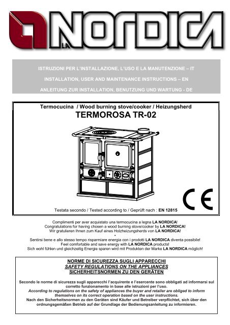
Termocucina / Wood burning stove/cooker / Heizungsherd<br />
<strong>TERMOROSA</strong> <strong>TR</strong>-<strong>02</strong><br />
Testata secondo / Tested according to / Geprüft nach : EN 12815<br />
Complimenti per aver acquistato una termocucina a legna LA NORDICA!<br />
Congratulations for having chosen a wood burning stove/cooker by LA NORDICA!<br />
Wir gratulieren Ihnen zum Kauf eines Holzheizungsherds von LA NORDICA!<br />
•<br />
Sentirsi bene e allo stesso tempo risparmiare energia con i prodotti LA NORDICA diventa possibile!<br />
Feel comfortable and save energy with LA NORDICA products!<br />
Sich wohl fühlen und gleichzeitig Energie sparen wird mit Produkten der Marke LA NORDICA möglich!<br />
NORME DI SICUREZZA SUGLI APPARECCHI<br />
SAFETY REGULATIONS ON THE APPLIANCES<br />
SICHERHEITSNORMEN ZU DEN GERÄTEN<br />
|<br />
Secondo le norme di sicurezza sugli apparecchi l’acquirente e l’esercente sono obbligati ad informarsi sul<br />
corretto funzionamento in base alle istruzioni per l’uso.<br />
According to regulations on the safety of appliances the buyer and retailer are obliged to inform<br />
themselves on its correct operation based on the user instructions.<br />
Nach den Sicherheitsnormen zu den Geräten sind Käufer und Betreiber verpflichtet, sich über den<br />
ordnungsgemäßen Betrieb auf der Grundlage der Bedienungsanleitung zu informieren.
Termocucina / Wood burning stove/cooker / Heizungsherd – <strong>TERMOROSA</strong> <strong>TR</strong><strong>02</strong><br />
DICHIARAZIONE DI CONFORMITA’ DEL COS<strong>TR</strong>UTTORE<br />
Oggetto: assenza di amianto e cadmio<br />
Si dichiara che tutti i nostri apparecchi vengono assemblati con materiali che non presentano parti di<br />
amianto o suoi derivati e che nel materiale d’apporto utilizzato per le saldature non è presente/utilizzato in<br />
nessuna forma il cadmio, come previsto dalla norma di riferimento.<br />
Oggetto: Regolamento CE n. 1935/2004<br />
Si dichiara che in tutti gli apparecchi da noi prodotti, i materiali destinati a venire a contatto con i cibi sono<br />
adatti all’uso alimentari, in conformità al Regolamento CE in oggetto.<br />
DECLARATION OF CONFORMITY OF THE MANUFACTURER<br />
Object: Absence of asbestos and cadmium<br />
We declare that the materials used for the assembly of all our appliances are without asbestos parts or<br />
asbestos derivates and that in the material used for welding, cadmium is not present, as prescribed in<br />
relevant norm.<br />
Object: CE n. 1935/2004 regulation.<br />
We declare that in all products we produce, the materials which will get in touch with food are suitable for<br />
alimentary use, according to the a.m. CE regulation.<br />
KONFORMITÄTSERKLÄRUNG DES HERSTELLERS<br />
Betreff: Fehlen von Asbest und Kadmium<br />
Wir bestätigen, dass die verwendeten Materialen oder Teilen für die Herstellung der La Nordica Geräte<br />
ohne Asbest und Derivat sind und auch das Lot für das Schweißen immer ohne Kadmium ist.<br />
Betreff: Ordnung CE n. 1935/2004. Wir erklären in alleiniger Verantwortung, dass die Materialien der<br />
Teile, die für den Kontakt mit Lebensmitteln vorgesehen sind, für die Nahrungsbenutzung geeignet sind<br />
und der Richtlinien CE n. 1935/2004 erfüllen<br />
2 Istruzioni / Instructions / Installation – IT – EN – DE – Rev.07
Termocucina / Wood burning stove/cooker / Heizungsherd – <strong>TERMOROSA</strong> <strong>TR</strong><strong>02</strong><br />
INDICE IT<br />
1. DATI TECNICI ................................................................................................................................................... 5<br />
2. DESCRIZIONE TECNICA .................................................................................................................................. 6<br />
3. NORME PER L’INSTALLAZIONE ...................................................................................................................... 7<br />
4. SICUREZZA ANTINCENDIO ............................................................................................................................. 9<br />
4.1. PRONTO INTERVENTO .......................................................................................................................................... 10<br />
5. CANNA FUMARIA ........................................................................................................................................... 10<br />
5.1. POSIZIONE DEL COMIGNOLO................................................................................................................................ 11<br />
6. COLLEGAMENTO AL CAMINO ....................................................................................................................... 12<br />
7. AFFLUSSO D’ARIA NEL LUOGO D’INSTALLAZIONE DURANTE LA COMBUSTIONE ................................... 13<br />
8. COMBUSTIBILI AMMESSI / NON AMMESSI................................................................................................... 13<br />
9. ACCENSIONE ................................................................................................................................................. 14<br />
10. FUNZIONAMENTO NORMALE.................................................................................................................... 15<br />
11. USO DEL FORNO ....................................................................................................................................... 16<br />
12. UTILIZZO CORRETTO PER IL RISCALDAMENTO CEN<strong>TR</strong>ALIZZATO. ....................................................... 16<br />
13. MANCANZA DI ENERGIA ELET<strong>TR</strong>ICA........................................................................................................ 17<br />
14. FUNZIONAMENTO NEI PERIODI <strong>TR</strong>ANSIZIONE........................................................................................ 17<br />
14.1. UTILIZZO COME NORMALE CUCINA...................................................................................................................... 17<br />
15. MANUTENZIONE E CURA .......................................................................................................................... 18<br />
15.1. PULIZIA CANNA FUMARIA...................................................................................................................................... 18<br />
15.2. PULIZIA VE<strong>TR</strong>O ...................................................................................................................................................... 19<br />
15.3. PULIZIA CASSETTO CENERE................................................................................................................................. 19<br />
15.4. LE MAIOLICHE........................................................................................................................................................ 19<br />
15.5. MANUTENZIONE DELL’IMPIANTO IDRAULICO ...................................................................................................... 19<br />
16. FERMO ESTIVO.......................................................................................................................................... 19<br />
17. COLLEGAMENTO ALLA CANNA FUMARIA DI UN CAMINETTO O FOCOLARE APERTO ......................... 20<br />
18. MONTAGGIO CORRIMANO LATERALI / ASSEMBLING SIDE RAILS / MONTIEREN DES SEITLICHEN<br />
HANDLAUFS........................................................................................................................................................... 53<br />
19. SCHEDA TECNICA / TECHNICAL SPECIFICATIONS / TECHNISCHE BESCHREIBUNG........................... 53<br />
20. SCHEMA DI INSTALLAZIONE / LAY-OUT / INSTALLATION SCHEME........................................................ 54<br />
TABLE OF CONTENTS EN<br />
1. TECHNICAL DATA .......................................................................................................................................... 21<br />
2. TECHNICAL DESCRIPTION............................................................................................................................ 22<br />
3. INSTALLATION RULES................................................................................................................................... 23<br />
4. FIRE SAFETY.................................................................................................................................................. 25<br />
4.1. FIRST AID ............................................................................................................................................................... 25<br />
5. FLUE ............................................................................................................................................................... 26<br />
5.1. POSITION OF CHIMNEY CAP ................................................................................................................................. 26<br />
6. CONNECTION TO THE CHIMNEY.................................................................................................................. 28<br />
7. INFLUX OF AIR IN THE SPACE OF INSTALLATION DURING COMBUSTION ............................................... 28<br />
8. ALLOWED/FORBIDDEN FUELS...................................................................................................................... 29<br />
9. TURNING ON.................................................................................................................................................. 30<br />
10. NORMAL OPERATION................................................................................................................................ 31<br />
11. USE OF OVEN ............................................................................................................................................ 31<br />
12. CORRECT USE FOR CEN<strong>TR</strong>AL HEATING. ................................................................................................ 32<br />
13. NO ELEC<strong>TR</strong>ICITY ....................................................................................................................................... 32<br />
14. OPERATION IN <strong>TR</strong>ANSITION PERIODS..................................................................................................... 32<br />
14.1. USE AS NORMAL STOVE/COOKER........................................................................................................................ 33<br />
15. CARE AND MAINTENANCE........................................................................................................................ 33<br />
15.1. CLEANING FLUE..................................................................................................................................................... 33<br />
15.2. CLEANING OF GLASS ............................................................................................................................................ 34<br />
15.3. CLEANING ASH DRAWER ...................................................................................................................................... 34<br />
15.4. THE MAJOLICA....................................................................................................................................................... 34<br />
15.5. MAINTENANCE ON THE WATER SYSTEM............................................................................................................. 34<br />
16. SUMMER PERIOD OF INACTIVITY............................................................................................................. 34<br />
17. CONNECTING A CHIMNEY OR OPEN FURNACE TO THE FLUE .............................................................. 35<br />
18. MONTAGGIO CORRIMANO LATERALI / ASSEMBLING SIDE RAILS / MONTIEREN DES SEITLICHEN<br />
HANDLAUFS........................................................................................................................................................... 53<br />
19. SCHEDA TECNICA / TECHNICAL SPECIFICATIONS / TECHNISCHE BESCHREIBUNG........................... 53<br />
20. SCHEMA DI INSTALLAZIONE / LAY-OUT / INSTALLATION SCHEME........................................................ 54<br />
Istruzioni / Instructions / Installation – IT – EN – DE – Rev.07 3
Termocucina / Wood burning stove/cooker / Heizungsherd – <strong>TERMOROSA</strong> <strong>TR</strong><strong>02</strong><br />
INHALTSVERZEICHNIS DE<br />
1. TECHNISCHE DATEN..................................................................................................................................... 36<br />
2. TECHNISCHE BESCHREIBUNG..................................................................................................................... 37<br />
3. INSTALLATIONSVORSCHRIFTEN.................................................................................................................. 38<br />
4. BRANDSCHUTZ.............................................................................................................................................. 40<br />
4.1. SOFORTIGES EINSCHREITEN ............................................................................................................................... 41<br />
5. RAUCHABZUG................................................................................................................................................ 41<br />
5.1. SCHORNSTEINPOSITION....................................................................................................................................... 42<br />
6. ANSCHLUSS AN DEN SCHORNSTEIN........................................................................................................... 44<br />
7. LUFTZUS<strong>TR</strong>OM AM INSTALLATIONSORT WÄHREND DER VERBRENNUNG.............................................. 44<br />
8. ZULÄSSIGE / UNZULÄSSIGE BRENNSTOFFE .............................................................................................. 45<br />
9. ANZÜNDEN..................................................................................................................................................... 45<br />
10. NORMALER BE<strong>TR</strong>IEB................................................................................................................................. 47<br />
11. BENUTZUNG DES BACKOFENS ................................................................................................................ 47<br />
12. RICHTIGER GEBRAUCH ZUR ZEN<strong>TR</strong>ALHEIZUNG.................................................................................... 48<br />
13. S<strong>TR</strong>OMAUSFALL ........................................................................................................................................ 48<br />
14. BE<strong>TR</strong>IEB IN DER ÜBERGANGSZEIT.......................................................................................................... 49<br />
14.1. VERWENDUNG ALS NORMALER HERD................................................................................................................. 49<br />
15. INSTANDHALTUNG UND PFLEGE ............................................................................................................. 49<br />
15.1. REINIGUNG DES RAUCHABZUGS.......................................................................................................................... 49<br />
15.2. REINIGUNG DER GLASSCHEIBE ........................................................................................................................... 50<br />
15.3. REINIGUNG DES ASCHEKASTENS........................................................................................................................ 51<br />
15.4. DIE MAJOLIKAKACHELN ........................................................................................................................................ 51<br />
15.5. WARTUNG DER HYDRAULIKANLAGE.................................................................................................................... 51<br />
16. STILLSTAND IM SOMMER.......................................................................................................................... 51<br />
17. ANSCHLUSS AN DEN RAUCHABZUG EINES OFFENEN KAMINS ............................................................ 51<br />
18. MONTAGGIO CORRIMANO LATERALI / ASSEMBLING SIDE RAILS / MONTIEREN DES SEITLICHEN<br />
HANDLAUFS........................................................................................................................................................... 53<br />
19. SCHEDA TECNICA / TECHNICAL SPECIFICATIONS / TECHNISCHE BESCHREIBUNG........................... 53<br />
20. SCHEMA DI INSTALLAZIONE / LAY-OUT / INSTALLATION SCHEME........................................................ 54<br />
4 Istruzioni / Instructions / Installation – IT – EN – DE – Rev.07
Termocucina – <strong>TERMOROSA</strong> <strong>TR</strong><strong>02</strong><br />
Definizione: termocucina secondo EN 12815<br />
1. DATI TECNICI<br />
<strong>TERMOROSA</strong><br />
Potenza termica globale in kW 19.9<br />
Potenza termica utile in kW 15.5<br />
Potenza resa all’acqua in kW 7<br />
Potenza resa all’ambiente in kW 8.5<br />
Consumo orario legna in kg / h (legna con 20% umidità) 4. 5<br />
Rendimento in % 79<br />
CO misurato al 13% di ossigeno in % 0.75<br />
Diametro tubo uscita fumi in mm 150 S/P<br />
Diametro canna fumaria in mm 5m 220x220 Ø220*<br />
Contenuto di acqua nella caldaia in lt 16<br />
Depressione al camino in mm H2O 1,7 – 2,0<br />
Diametro raccordi mandata e ritorno in pollici gas 1”F gas<br />
Sezione presa aria esterna Ø in mm 200<br />
Emissione gas di scarico in g/s – legna 18.89<br />
Temperatura gas di scarico nel mezzo in °C - legna 247<br />
Temperatura ottimale di esercizio in °C 70 ÷ 75<br />
Pressione max d’esercizio in bar 1.5<br />
Dimensioni apertura focolare in mm (LxH) 220 x 265<br />
Dimensioni corpo focolare / testata focolare in mm (LxHxP) 265 x 285 x 400<br />
Dimensioni forno in mm (L x H x P) 330 x 300 x 410<br />
Tipo di griglia Movibile, piana<br />
Altezza termocucina in mm 852<br />
Larghezza termocucina in mm 1017<br />
Profondità termocucina (con maniglie) in mm 662<br />
Peso in Kg 200 / 216<br />
Distanze di sicurezza antincendio Capitolo 4<br />
* Diametro 200 mm utilizzabile con canna fumaria non inferiore a 6 m<br />
Il volume di riscaldamento delle cucine secondo EN 12815, per edifici il cui isolamento termico non<br />
corrisponde alle disposizioni sulla protezione del calore, è:<br />
(30 Kcal/h x m 3 ) - tipo di costruzione favorevole: 444 m³<br />
(40 Kcal/h x m 3 ) - tipo di costruzione meno favorevole: 333 m³<br />
(50 Kcal/h x m 3 ) - tipo di costruzione sfavorevole: 266 m³<br />
Con un isolamento termico secondo le norme sul risparmio energetico il volume riscaldato è maggiore.<br />
Con un riscaldamento temporaneo, in caso di interruzioni superiori a 8h, la capacità di riscaldamento<br />
diminuisce del 25% circa.<br />
IMPORTANTE: La potenza dell’impianto termico collegato deve essere commisurata alla potenza<br />
ceduta all’acqua dalla termocucina; un carico troppo ridotto non consente un<br />
regolare funzionamento del forno, mentre un carico troppo elevato impedisce un<br />
adeguato riscaldamento dei radiatori.<br />
Istruzioni per l’installazione, l’uso e la manutenzione – IT – Rev.07 5
2. DESCRIZIONE TECNICA<br />
Termocucina – <strong>TERMOROSA</strong> <strong>TR</strong><strong>02</strong><br />
Le termocucine La Nordica si addicono a riscaldare spazi abitativi dotati di un impianto di riscaldamento<br />
centralizzato costituito da radiatori o da termoconvettori sostituendo del tutto o in parte la tradizionale<br />
caldaia a gas o gasolio. Esse sono ideali per appartamenti di vacanza e case del fine settimana oppure<br />
come riscaldamento ausiliario durante tutto l’anno.<br />
Come combustibili vengono utilizzati ceppi di legna.<br />
La termocucina è costituita di lastre in lamiera d’acciaio zincata, ghisa smaltata e ceramica termo-radiante.<br />
Il focolare si trova all’interno della caldaia costruita con acciaio di 4 mm di spessore e rinforzata con chiodi<br />
saldati. Nella caldaia circola l’acqua dell’impianto di riscaldamento la quale assorbe il calore prodotto nel<br />
focolare. All’interno del focolare si trova una griglia piana regolabile in altezza.<br />
Il focolare è dotato di una porta panoramica con vetro ceramico (resistente fino a 700°C). Questo cons ente<br />
un’affascinante vista sulle fiamme ardenti. Inoltre viene così impedita ogni possibile fuoriuscita di scintille e<br />
fumo.<br />
Il riscaldamento dell’ambiente avviene:<br />
a) per irraggiamento: attraverso il vetro panoramico e le superfici esterne calde della stufa viene<br />
irraggiato calore nell’ambiente.<br />
b) mediante i radiatori o termoconvettori dell’impianto centralizzato alimentati dall’acqua calda<br />
prodotta dalla Termocucina stessa.<br />
La termocucina è fornita di registri per l’aria primaria e secondaria e di un termostato, con i quali viene<br />
regolata l’aria di combustione.<br />
REGIS<strong>TR</strong>O ARIA PRIMARIA (valvola girevole)<br />
Con il registro inferiore (Figura 1 pos. A) viene regolato il<br />
passaggio dell’aria primaria nella parte bassa della cucina<br />
attraverso il cassetto cenere e la griglia in direzione del<br />
combustibile. L’aria primaria è necessaria per il processo<br />
di combustione. Il cassetto cenere deve essere svuotato<br />
regolarmente, in modo che la cenere non possa<br />
ostacolare l’entrata dell’aria primaria per la combustione.<br />
Attraverso l’aria primaria viene anche mantenuto vivo il<br />
fuoco.<br />
REGIS<strong>TR</strong>O ARIA SECONDARIA<br />
Sopra la porta del focolare si trova il registro dell’aria<br />
secondaria (Figura 1 pos. B). Questa valvola deve essere<br />
aperta (quindi spostata verso destra) in particolare per la<br />
combustione di legna – vedi paragrafo 10.<br />
Figura 1<br />
TERMOSTATO<br />
Il termostato ha la funzione di aumentare o diminuire automaticamente la combustione (Figura 1 pos. C).<br />
A seconda della posizione scelta il termostato agirà sulla valvola d’immissione d’aria al focolare (posta<br />
sulla schiena della cucina). Ruotare in senso orario dallo 0 al 5 per ravvivare il fuoco e dal 5 allo 0 in senso<br />
antiorario per ridurre la combustione. Trattandosi di un dispositivo di elevata precisione si raccomanda di<br />
ruotare con cura e non forzare mai la manopola.<br />
REGIS<strong>TR</strong>O - FUMI<br />
(Conversione dalla funzione di cucina a quella di cucina - cottura al forno e riscaldamento)<br />
Sulla destra del lato anteriore della cucina, tra il corrimano di protezione e la porta del forno, si trova la leva<br />
di comando del registro-fumi, riconoscibile da un pomolo in ottone (Figura 1 pos. D).<br />
Quando si spinge la leva verso il retro della cucina, i gas di combustione fluiscono sopra il forno<br />
direttamente verso il tronchetto di scarico (funzione cucina – USO PIAS<strong>TR</strong>A); quando invece si tira la<br />
leva verso di sé, i gas di combustione fluiscono tutt‘intorno al forno, cosicché la sua temperatura interna<br />
aumenta in modo uniforme (funzione cucina-cottura al forno e riscaldamento – USO FORNO).<br />
6 Istruzioni per l’installazione, l’uso e la manutenzione – IT – Rev.07<br />
B<br />
A<br />
D<br />
C
Termocucina – <strong>TERMOROSA</strong> <strong>TR</strong><strong>02</strong><br />
3. NORME PER L’INSTALLAZIONE<br />
L’installazione della termostufa e degli equipaggiamenti ausiliari, relativi all’impianto di riscaldamento, deve<br />
essere conforme e tutte le Norme e Regolamentazioni attuali ed a quanto previsto dalla Legge.<br />
L’installazione, i relativi collegamenti dell’impianto, la messa in servizio e la verifica del corretto<br />
funzionamento devono essere eseguiti a regola d’arte da personale professionalmente autorizzato nel<br />
pieno rispetto delle norme vigenti, sia nazionali, regionali, provinciali e comunali presenti nel paese in cui è<br />
stato installato l’apparecchio, nonché delle presenti istruzioni.<br />
L’installazione deve essere eseguita da personale autorizzato, che dovrà rilasciare all’acquirente una<br />
dichiarazione di conformità dell’impianto, il quale si assumerà l’intera responsabilità dell’installazione<br />
definitiva e del conseguente buon funzionamento del prodotto installato.<br />
Non vi sarà responsabilità da parte di La NORDICA S.p.A. in caso di mancato rispetto di tali precauzioni.<br />
Prima dell’installazione, si consiglia di effettuare un lavaggio accurato di tutte le tubazioni dell’impianto<br />
onde rimuovere eventuali residui che potrebbero compromettere il buon funzionamento dell’apparecchio.<br />
IMPORTANTE:<br />
a) In caso di fuoriuscite d’acqua chiudere l’alimentazione idrica ed avvisare con sollecitudine il servizio<br />
tecnico di assistenza;<br />
b) La pressione di esercizio dell’impianto deve essere periodicamente controllata.<br />
c) In caso di non utilizzo della caldaia per un lungo periodo è consigliabile l’intervento del servizio tecnico<br />
di assistenza per effettuare almeno le seguenti operazioni:<br />
- chiudere i rubinetti dell’acqua sia dell’impianto termico sia del sanitario;<br />
- svuotare l’impianto termico e sanitario se c’è rischio di gelo.<br />
La Nordica S.p.a. declina ogni responsabilità per danni a cose e/o persone provocati dall’impianto.<br />
Inoltre non è responsabile del prodotto modificato senza autorizzazione e tanto meno per l’uso di<br />
ricambi non originali.<br />
Il Vostro abituale spazzacamino di zona deve essere informato sull’installazione della termocucina,<br />
affinché possa verificarne il regolare collegamento alla canna fumaria ed il grado di efficienza di<br />
quest’ultima.<br />
NON SI POSSONO EFFETTUARE MODIFICHE ALL’APPARECCHIO.<br />
Prima dell’installazione, verificate se il Vostro pavimento può sopportare il peso della Termocucina.<br />
ATTENZIONE: assicurarsi che l’apparecchio sia posto perfettamente in piano e che il diametro del<br />
tubo di scarico dei fumi sia quello richiesto.<br />
Non è concesso il collegamento di più stufe allo stesso camino.<br />
Vi consigliamo di far verificare dal Vostro abituale spazzacamino di zona sia il collegamento al camino sia il<br />
sufficiente afflusso d’aria per la combustione nel luogo d’installazione.<br />
Il diametro dell’apertura per il collegamento al camino deve corrispondere per lo meno al diametro del tubo<br />
fumo. L’apertura dovrebbe essere dotata di una connessione a muro per l’inserimento del tubo di scarico e<br />
di un rosone.<br />
Il foro di scarico fumi non utilizzato deve essere ricoperto con il relativo tappo.<br />
Le termocucina modello <strong>TERMOROSA</strong> va OBBLIGATORIAMENTE installata in un impianto a VASO DI<br />
ESPANSIONE APERTO.<br />
L’impianto con vaso di espansione aperto, deve essere obbligatoriamente provvisto di:<br />
1. VASO DI ESPANSIONE APERTO: avente una capacità pari al 10 % del contenuto d’acqua totale della<br />
termocucina e dell’impianto. Questa va posizionata nel punto più alto dell’impianto almeno 2m sopra il<br />
radiatore posto al livello più alto.<br />
2. TUBO DI SICUREZZA : che collega per la via più breve, senza tratti discendenti o sifonanti la mandata<br />
della termocucina con la parte superiore della vaschetta descritta al punto 1.<br />
Il tubo di sicurezza deve avere la sezione minima di 1’’.<br />
3. TUBO DI CARICO : che collega il fondo della vaschetta del punto 1 con il tubo di ritorno dell’impianto.<br />
La sezione minima deve essere di ¾’’.<br />
Tutti questi elementi non devono per nessuna ragione avere organi di intercettazione interposti che<br />
possano accidentalmente escluderli e devono essere posizionati in ambienti non esposti al gelo<br />
poiché, se dovessero gelare, si potrebbe verificare la rottura o addirittura l’esplosione del corpo<br />
caldaia.<br />
Istruzioni per l’installazione, l’uso e la manutenzione – IT – Rev.07 7
Termocucina – <strong>TERMOROSA</strong> <strong>TR</strong><strong>02</strong><br />
In caso di esposizione al gelo sarà opportuno aggiungere all’acqua dell’impianto una adeguata<br />
percentuale di liquido antigelo che consentirà di eliminare completamente il problema.<br />
In nessun modo dovrà esserci circolazione d’acqua nella vaschetta fra il tubo di sicurezza ed il tubo di<br />
carico poiché questa provoca l’ossigenazione dell’acqua stessa e la conseguente corrosione del corpo<br />
della termocucina e dell’impianto in tempi molto brevi.<br />
4. VALVOLA DI SCARICO TERMICO: costituisce una ulteriore sicurezza positiva in grado di prevenire<br />
l’ebollizione anche in assenza di energia elettrica.<br />
E’ costituita da un corpo valvola simile ad una valvola di sicurezza a pressione che, a differenza di<br />
questa, si apre al raggiungimento di una temperatura pretarata ( di solito 94 – 95° C ) scaricando dal la<br />
mandata dell’impianto acqua calda che verrà sostituita con altrettanta acqua fredda proveniente<br />
attraverso il tubo di carico dalla vaschetta del vaso aperto smaltendo in questo modo il calore<br />
eccessivo.<br />
5. VALVOLA DI SICUREZZA da 1,5bar: la massima pressione di esercizio ammessa per l’impianto è di<br />
1,5bar (pari a 15m di colonna d’acqua), pressioni superiori possono provocare deformazioni e rotture<br />
del corpo caldaia.<br />
6. AL<strong>TR</strong>I DISPOSITIVI di sicurezza previsti dalla Normativa vigente in materia.<br />
7. POMPA DI CIRCOLAZIONE: dovrebbe preferibilmente essere montata sul ritorno per evitare che<br />
possa disinnescarsi a temperature dell’acqua molto elevate accertandosi però che non faccia circolare<br />
l’acqua nella vaschetta del vaso aperto altrimenti provocherebbe una continua ossigenazione<br />
dell’acqua con conseguente, rapida, corrosione del corpo caldaia.<br />
Deve inoltre essere collegata elettricamente in modo da funzionare solamente quando la temperatura<br />
dell’acqua supera i 65-70° C ; per ottenere questo si potrà usare la centralina elettronica fornibile come<br />
OPTIONAL assieme alla termocucina, oppure utilizzando un termostato a bracciale montato<br />
immediatamente sulla mandata e tarato appunto a 65-70° C.<br />
8. VALVOLA MISCELA<strong>TR</strong>ICE TERMOSTATICA AUTOMATICA - Figura 2<br />
La valvola miscelatrice termostatica automatica trova applicazione nei termoprodotti a combustibile<br />
solido in quanto previene il ritorno di acqua fredda nello scambiatore.<br />
Le tratte 1 e 3 sono sempre aperte e, assieme alla pompa installata sul ritorno (R), garantiscono la<br />
circolazione dell’acqua all’interno dello scambiatore della caldaia a biomassa (CB).<br />
Una elevata temperatura di ritorno permette di migliorare l’efficienza, riduce la formazione di condensa<br />
dei fumi e allunga la vita della caldaia.<br />
Le valvole in commercio presentano svariate tarature, La NORDICA consiglia l’utilizzo del modello<br />
55°C con connessioni idrauliche da 1”. Una volta ra ggiunta la temperatura di taratura della valvola,<br />
viene aperta la tratta 2 e l’acqua della caldaia va all’impianto attraverso la mandata (M).<br />
CB<br />
TERMOPRODOTTO<br />
55°<br />
Figura 2<br />
IMPORTANTE la mancata installazione del dispositivo fa decadere la garanzia dello scambiare<br />
di calore.<br />
IMPORTANTE: i sensori di sicurezza della temperatura devono essere a bordo macchina o a una distanza<br />
non maggiore di 30 cm dal collegamento di mandata del termoprodotto.<br />
Qualora i termoprodotti non siano provvisti di tutti i dispostivi, quelli mancanti possono essere installati sulla<br />
tubazione di mandata del termoprodotto entro una distanza dal termoprodotto non maggiore di 1 m.<br />
ATTENZIONE : Per nessuna ragione si dovrà accendere il fuoco prima che l’impianto non sia stato<br />
completamente riempito d’acqua; il farlo comporterebbe un danneggiamento<br />
8 Istruzioni per l’installazione, l’uso e la manutenzione – IT – Rev.07<br />
1<br />
3<br />
2<br />
M<br />
R
Termocucina – <strong>TERMOROSA</strong> <strong>TR</strong><strong>02</strong><br />
gravissimo a tutta la struttura. Il riempimento dell’impianto deve essere fatto tramite il<br />
tubo di carico direttamente dalla vaschetta del vaso aperto in modo da evitare che una<br />
eccessiva pressione della rete idrica deformi il corpo della termocucina.<br />
L’impianto va tenuto costantemente pieno d’acqua anche nei periodi in cui non è richiesto l’uso della<br />
termocucina. Durante il periodo invernale un’eventuale non attività va affrontata con l’aggiunta di sostanze<br />
antigelo.<br />
4. SICUREZZA ANTINCENDIO<br />
Nell’installazione della termocucina devono essere osservate le seguenti misure di sicurezza:<br />
a) la distanza minima da elementi costruttivi ed oggetti infiammabili e sensibili al calore (mobili,<br />
rivestimenti di legno, stoffe ecc.) deve essere di 30cm dal retro e da entrambi i lati; al fine di assicurare<br />
un sufficiente isolamento termico (vedi Figura 3 A).<br />
b) davanti alla porta del focolare, nell’area di radiazione della stessa, non deve esserci alcun oggetto o<br />
materiale di costruzione infiammabile e sensibile al calore a meno di 100 cm di distanza. Tale distanza<br />
può essere ridotta a 40 cm qualora venga installata una protezione, retroventilata e resistente al calore,<br />
davanti all’intero componente da proteggere. Tutte le distanze minime di sicurezza sono indicate<br />
sulla targhetta del prodotto e non si deve scendere al di sotto delle stesse.<br />
c) qualora la termocucina venga installata su un pavimento di materiale infiammabile, bisogna prevedere<br />
un sottofondo ignifugo, per esempio una pedana d'acciaio (dimensioni secondo l’ordinamento<br />
regionale). Il sottofondo deve sporgere frontalmente di almeno 50 cm e lateralmente di almeno 30 cm<br />
oltre all’apertura della porta di carico (vedi Figura 3 B).<br />
d) sopra la termocucina non devono essere presenti componenti infiammabili (es. pensili).<br />
La termocucina deve funzionare esclusivamente con il cassetto cenere inserito. I residui solidi della<br />
combustione (ceneri) devono essere raccolti in un contenitore ermetico e resistente al fuoco. La<br />
termocucina non deve mai essere accesa in presenza di emissioni gassose o vapori (per esempio colla per<br />
linoleum, benzina ecc.). Non depositate materiali infiammabili nelle vicinanze della termocucina.<br />
Durante la combustione viene sprigionata energia termica che comporta un marcato riscaldamento delle<br />
superfici, di porte, maniglie, comandi, vetri, tubo fumi ed eventualmente della parte anteriore<br />
dell’apparecchio. Evitate il contatto con tali elementi senza un corrispondente abbigliamento protettivo o<br />
senza utensili accessori (guanti resistenti al calore, dispositivi di comando).<br />
Fate in modo che i bambini siano consapevoli di questi pericoli e teneteli lontani dal focolare<br />
durante il suo funzionamento.<br />
Quando si utilizza un combustibile errato o troppo umido, a causa di depositi presenti nella canna fumaria<br />
si potrebbe avere un incendio della stessa.<br />
Figura 3<br />
A B<br />
Istruzioni per l’installazione, l’uso e la manutenzione – IT – Rev.07 9
4.1. PRONTO INTERVENTO<br />
Se si manifesta un incendio nel collegamento o nella canna fumaria :<br />
a) Chiudere la porta di caricamento e del cassetto cenere.<br />
b) Chiudere i registri dell’aria comburente<br />
c) Spegnere tramite l’uso di estintori ad anidride carbonica ( CO2 a polveri )<br />
d) Richiedere l’immediato intervento dei Vigili del Fuoco<br />
Termocucina – <strong>TERMOROSA</strong> <strong>TR</strong><strong>02</strong><br />
Non spegnere il fuoco con l’uso di getti d’acqua.<br />
Quando la canna fumaria smette di bruciare farla verificare da uno specialista per individuare eventuali<br />
crepe o punti permeabili.<br />
5. CANNA FUMARIA<br />
Requisiti fondamentali per un corretto funzionamento<br />
dell’apparecchio:<br />
• la sezione interna deve essere preferibilmente<br />
circolare;<br />
• essere termicamente isolata ed impermeabile e<br />
costruita con materiali idonei a resistere al calore,<br />
ai prodotti della combustione ed alle eventuali<br />
condense;<br />
• essere priva di strozzature ed avere andamento<br />
verticale con deviazioni non superiori a 45°;<br />
• se già usata deve essere pulita;<br />
• rispettare i dati tecnici del manuale di istruzioni;<br />
Qualora le canne fumarie fossero a sezione quadrata o<br />
rettangolare gli spigoli interni devono essere arrotondati<br />
con raggio non inferiore a 20 mm. Per la sezione<br />
rettangolare il rapporto massimo tra i lati deve essere ≤<br />
1,5.<br />
Una sezione troppo piccola provoca una diminuzione del<br />
tiraggio. Si consiglia un’altezza minima di 4 m.<br />
Sono vietate e pertanto pregiudicano il buon<br />
funzionamento dell’apparecchio: fibrocemento, acciaio<br />
zincato, superfici interne ruvide e porose. In Fig. 4 sono<br />
riportati alcuni esempi di soluzione.<br />
La sezione minima deve essere di 4 dm 2 (per esempio<br />
20x20cm) per gli apparecchi il cui diametro di<br />
condotto è inferiore a 200mm, o 6,25dm 2 (per<br />
esempio 25x25cm) per gli apparecchi con diametro<br />
superiore a 200mm.<br />
(1) (2)<br />
(1) Canna fumaria in acciaio AISI 316 con doppia<br />
camera isolata con materiale resistente a<br />
400°C. Efficienza 100% ottima.<br />
(2) Canna fumaria in refrattario con doppia<br />
camera isolata e rivestimento esterno in<br />
calcestruzzo alleggerito. Efficienza 100%<br />
ottima.<br />
(3) Canna fumaria tradizionale in argilla sezione<br />
quadrata con intercapedini. Efficienza 80%<br />
ottima.<br />
(4) Evitare canne fumarie con sezione<br />
rettangolare interna il cui rapporto sia diverso<br />
dal disegno.<br />
Efficienza 40% mediocre.<br />
Fig. 4<br />
Il tiraggio creato dalla vostra canna fumaria deve essere sufficiente ma non eccessivo.<br />
Una sezione della canna fumaria troppo importante può presentare un volume troppo grande da riscaldare<br />
e dunque provocare delle difficoltà di funzionamento dell’apparecchio; per evitare ciò provvedete ad<br />
intubare la stessa per tutta la sua altezza. Una sezione troppo piccola provoca una diminuzione del<br />
tiraggio.<br />
La canna fumaria deve essere adeguatamente distanziata da materiali infiammabili o combustibili<br />
mediante un opportuno isolamento o un’intercapedine d’aria.<br />
E’ vietato far transitare all’interno della stessa tubazioni di impianti o canali di adduzione d’aria. E’ proibito<br />
inoltre praticare aperture mobili o fisse, sulla stessa, per il collegamento di ulteriori apparecchi diversi (Vedi<br />
capitolo .17 ).<br />
10 Istruzioni per l’installazione, l’uso e la manutenzione – IT – Rev.07<br />
(3)<br />
(4)<br />
A+1/2A<br />
Max.<br />
A+1/2A<br />
A
Termocucina – <strong>TERMOROSA</strong> <strong>TR</strong><strong>02</strong><br />
5.1. POSIZIONE DEL COMIGNOLO<br />
Il tiraggio della canna fumaria dipende anche dall’idoneità del comignolo.<br />
È pertanto indispensabile che, se costruito artigianalmente, la sezione di uscita sia più di due volte la<br />
sezione interna della canna fumaria.<br />
Dovendo sempre superare il colmo del tetto, il comignolo dovrà assicurare lo scarico anche in presenza di<br />
vento (Fig. 5).<br />
Il comignolo deve rispondere ai seguenti requisiti:<br />
• avere sezione interna equivalente a quella del camino.<br />
• avere sezione utile d’uscita doppia di quella interna della canna fumaria.<br />
• essere costruito in modo da impedire la penetrazione nella canna fumaria di pioggia, neve e di<br />
qualsiasi corpo estraneo.<br />
• essere facilmente ispezionabile, per eventuali operazioni di manutenzione e pulizia.<br />
(1) Comignolo industriale<br />
ad elementi prefabbricati,<br />
consente un ottimo<br />
smaltimento dei fumi.<br />
50 cm<br />
2 m 10 m<br />
1<br />
m<br />
(2) Comignolo artigianale.<br />
La giusta sezione di uscita<br />
deve essere minimo 2 volte<br />
la sezione interna della<br />
canna fumaria, ideale 2,5<br />
volte.<br />
(3) Comignolo per canna<br />
fumaria in acciaio con<br />
cono interno deflettore<br />
dei fumi.<br />
Fig. 5<br />
(1) In caso di canne fumarie affiancate un<br />
comignolo dovrà sovrastare l’altro d’almeno 50 cm<br />
al fine d’evitare trasferimenti di pressione tra le<br />
canne stesse.<br />
(1) Il comignolo non deve avere ostacoli entro i 10 m da muri,<br />
falde ed alberi. In caso contrario innalzare lo stesso d’almeno<br />
1 m sopra l’ostacolo.<br />
Il comignolo deve oltrepassare il colmo del tetto d’almeno 1 m.<br />
Istruzioni per l’installazione, l’uso e la manutenzione – IT – Rev.07 11<br />
Fig. 6<br />
Figura 7
6. COLLEGAMENTO AL CAMINO<br />
Figura 8<br />
COMIGNOLI DISTANZE E POSIZIONAMENTO UNI 10683/98<br />
Inclinazione del tetto Distanza tra il colmo e il camino<br />
Termocucina – <strong>TERMOROSA</strong> <strong>TR</strong><strong>02</strong><br />
Altezza minima del camino (misurata dallo<br />
sbocco)<br />
α A (m) H (m)<br />
15°<br />
30°<br />
45°<br />
60°<br />
H min.<br />
α<br />
>A<br />
< 1,85 m 0,50 m oltre il colmo<br />
> 1,85 m 1,00 m dal tetto<br />
< 1,50 m 0,50 m oltre il colmo<br />
> 1,50 m 1,30 m dal tetto<br />
< 1,30 m 0,50 m oltre il colmo<br />
> 1,30 m 2,00 m dal tetto<br />
< 1,20 m 0,50 m oltre il colmo<br />
> 1,20 m 2,60 m dal tetto<br />
Gli apparecchi con chiusura automatica della porta (tipo 1) devono obbligatoriamente funzionare, per<br />
motivi di sicurezza, con la porta del focolare chiusa (fatta eccezione per la fase di carico del combustibile o<br />
l’eventuale rimozione della cenere ).<br />
Gli apparecchi con le porte non a chiusura automatica (tipo 2) devono essere collegati ad una propria<br />
canna fumaria. Il funzionamento con porta aperta è consentito soltanto previa sorveglianza.<br />
ATTENZIONE: qualora il collegamento attraversi particolari composti da materiali infiammabili, nel raggio<br />
di 20cm attorno al tubo tutti i materiali infiammabili devono essere sostituiti da materiali<br />
ignifughi e resistenti al calore.<br />
Per un buon funzionamento dell’apparecchio è essenziale che nel luogo d’installazione venga immessa<br />
sufficiente aria per la combustione (vedi paragrafo 7).<br />
La termostufa è dotata di uno scarico fumi superiore. Il tubo di congiunzione per il collegamento al camino<br />
deve essere il più corto possibile ed i punti d’unione dei singoli tubi devono essere ermetici. Il collegamento<br />
al camino deve essere eseguito con tubi stabili e robusti (Vi consigliamo uno spessore di 2 mm). Il tubo di<br />
scarico fumi deve essere fissato ermeticamente al camino. Il diametro interno del tubo di collegamento<br />
deve corrispondere al diametro esterno del tronchetto di scarico fumi della termostufa. Ciò viene garantito<br />
dai tubi secondo DIN 1298.<br />
12 Istruzioni per l’installazione, l’uso e la manutenzione – IT – Rev.07<br />
><br />
_ A<br />
(1)Asse colmo<br />
(2)Tetto<br />
0,5 m
Termocucina – <strong>TERMOROSA</strong> <strong>TR</strong><strong>02</strong><br />
La depressione al camino (TIRAGGIO) deve essere di almeno 17-20 Pascal (=1,7-2,0 mm di colonna<br />
d’acqua). La misurazione deve essere fatta sempre ad apparecchio caldo (resa calorifica nominale).<br />
Quando la depressione supera i 20 Pascal (2,0 mm di colonna d’acqua) è necessario ridurre la stessa con<br />
l’installazione di un regolatore di tiraggio supplementare (valvola a farfalla) sul tubo di scarico o nel camino.<br />
7. AFFLUSSO D’ARIA NEL LUOGO D’INSTALLAZIONE DURANTE LA<br />
COMBUSTIONE<br />
Poiché le termocucine ricavano la loro aria di combustione dal locale di installazione, è essenziale che nel<br />
luogo stesso venga immessa una sufficiente quantità d’aria. In caso di finestre e porte a tenuta stagna (es<br />
.case costruite con il criterio di risparmio energetico) è possibile che l’ingresso di aria fresca non venga più<br />
garantito e questo compromette il tiraggio dell’apparecchio, il vostro benessere e la vostra sicurezza.<br />
Bisogna pertanto garantire una alimentazione aggiuntiva di aria fresca mediante una presa d’aria esterna<br />
posta nelle vicinanze dell’apparecchio oppure tramite la posa di una conduttura per l’aria di combustione<br />
che porti verso l’esterno od in un vicino locale areato, ad eccezione del locale caldaia o garage<br />
(VIETATO).<br />
Il tubo di collegamento deve essere liscio con un diametro minimo di 120 mm, deve avere una lunghezza<br />
massima di 4 m e presentare non più di tre curve. Qualora questo sia collegato direttamente con l’esterno<br />
deve essere dotato di un apposito frangivento.<br />
L’entrata dell’aria per la combustione nel luogo d’installazione non deve essere ostruita durante il<br />
funzionamento della termocucina. E’ assolutamente necessario che negli ambienti, in cui vengono fatte<br />
funzionare termocucine con un tiraggio naturale del camino, venga immessa tanta aria quanta ne è<br />
necessaria per la combustione, ossia fino a 25 m³/ora. Il naturale ricircolo dell’aria deve essere garantito da<br />
alcune aperture fisse verso l’esterno, la loro grandezza è stabilita da relative normative in materia.<br />
Chiedete informazioni al Vostro spazzacamino di fiducia. Le aperture devono essere protette con delle<br />
griglie e non devono mai essere otturate. Una cappa di estrazione (aspirante) installata nella stessa stanza<br />
od in una confinante provoca una depressione nell’ambiente. Questo provoca la fuoriuscita di gas combusti<br />
(fumo denso, odore); é dunque necessario assicurare un maggiore afflusso di aria fresca.<br />
La depressione di una cappa aspirante può, nella peggiore delle ipotesi, trasformare la canna<br />
fumaria della termocucina in presa d’aria esterna risucchiando i fumi nell’ambiente con<br />
conseguenze gravissime per le persone.<br />
8. COMBUSTIBILI AMMESSI / NON AMMESSI<br />
I combustibili ammessi sono ceppi di legna. Si devono utilizzare esclusivamente ceppi di legna secca<br />
(contenuto d’acqua max 20%). I pezzi di legna dovrebbero avere una lunghezza di circa 30 cm ed una<br />
circonferenza di 15 - 18 cm max.<br />
La legna usata come combustibile deve avere un contenuto d’umidità inferiore al 20% e la si ottiene con un<br />
tempo di essiccazione di almeno un anno (legno tenero) o di due anni (legno duro) collocandola in un<br />
luogo asciutto e ventilato (per esempio sotto una tettoia). La legna umida rende l’accensione più difficile,<br />
poiché è necessaria una maggiore quantità d’energia per far evaporare l’acqua presente. Il contenuto<br />
umido ha inoltre lo svantaggio, con l’abbassarsi della temperatura, di far condensare l’acqua prima nel<br />
focolare e quindi nel camino. La legna fresca contiene circa il 60% di H2O, perciò non è adatta ad essere<br />
bruciata.<br />
Tra gli altri non possono essere bruciati: resti di carbone, ritagli, cascami di corteccia e pannelli,<br />
legna umida o trattata con vernici, materiali di plastica; in tal caso decade la garanzia<br />
sull’apparecchio.<br />
Carta e cartone devono essere utilizzati solo per l’accensione. La combustione di rifiuti è vietata e<br />
danneggerebbe inoltre la termocucina e la canna fumaria, provocando inoltre danni alla salute ed in virtù<br />
del disturbo olfattivo a reclami da parte del vicinato.<br />
Istruzioni per l’installazione, l’uso e la manutenzione – IT – Rev.07 13
Termocucina – <strong>TERMOROSA</strong> <strong>TR</strong><strong>02</strong><br />
La legna non è un combustibile a lunga durata e pertanto non è possibile un riscaldamento continuo della<br />
termocucina durante la notte.<br />
ATTENZIONE: L'uso continuo e prolungato di legna particolarmente ricca di oli aromatici (p.e.<br />
Eucalipto, Mirto, etc.) provoca il deterioramento (sfaldamento) repentino dei<br />
componenti in ghisa presenti nel prodotto.<br />
9. ACCENSIONE<br />
LEGNA DA ARDERE DI USO COMUNE<br />
Specie Kg/mc<br />
KWh/kg<br />
Umidità 20%<br />
Faggio 750 4,0<br />
Cerro 900 4,2<br />
Olmo 640 4,1<br />
Pioppo 470 4,1<br />
Larice* 660 4,4<br />
Abete rosso* 450 4,5<br />
Pino silvestre* 550 4,4<br />
* LEGNI RESINOSI POCO ADATTI PER LA TERMOCUCINA<br />
ATTENZIONE : Per nessuna ragione si dovrà accendere il fuoco prima che l’impianto non sia stato<br />
completamente riempito d’acqua; il farlo comporterebbe un danneggiamento<br />
gravissimo a tutta la struttura.<br />
IMPORTANTE: alla prima accensione è inevitabile che venga prodotto un odore sgradevole (dovuto<br />
all’essiccamento dei collanti nella cordicella di guarnizione o delle vernici protettive), che<br />
sparisce dopo un breve utilizzo. Deve comunque essere assicurata una buona<br />
ventilazione dell’ambiente. Alla prima accensione Vi consigliamo di caricare una quantità<br />
ridotta di combustibile e di aumentare lentamente la resa calorifica dell’apparecchio.<br />
Per effettuare una corretta prima accensione dei prodotti trattati con vernici per alte temperature, occorre<br />
sapere quanto segue:<br />
• i materiali di costruzione dei prodotti in questione non sono omogenei, infatti coesistono parti in ghisa e<br />
in acciaio.<br />
• la temperatura alla quale il corpo del prodotto è sottoposto non è omogenea: da zona a zona si<br />
registrano temperature variabili dai 300 °C ai 500 °C;<br />
• durante la sua vita, il prodotto è sottoposto a cicli alternati di accensioni e di spegnimento durante la<br />
stessa giornata e a cicli di intenso utilizzo o di assoluto riposo al variare delle stagioni;<br />
• la termocucina nuova, prima di potersi definire rodata, dovrà essere sottoposta a diversi cicli di<br />
avviamento per poter consentire a tutti i materiali ed alla vernice di completare le varie sollecitazioni<br />
elastiche;<br />
• in particolare inizialmente si potrà notare l’emissione di odori tipici dei metalli sottoposti a grande<br />
sollecitazione termica e di vernice ancora fresca. Tale vernice, sebbene in fase di costruzione venga<br />
cotta a 250°C per qualche ora, dovrà superare più v olte e per una certa durata la temperatura di<br />
350°C, prima di incorporarsi perfettamente con le s uperfici metalliche<br />
Diventa quindi importante seguire questi piccoli accorgimenti in fase di accensione:<br />
1. Assicuratevi che sia garantito un forte ricambio d'aria nel luogo dove è installato l'apparecchio.<br />
2. Nelle prime accensioni, non caricare eccessivamente la camera di combustione (circa metà della<br />
quantità indicata nel manuale d'istruzioni) e tenere il prodotto acceso per almeno 6-10 ore di continuo,<br />
con i registri meno aperti di quanto indicato nel manuale d'istruzioni.<br />
3. Ripetere questa operazione per almeno 4-5 o più volte, secondo la Vostra disponibilità.<br />
14 Istruzioni per l’installazione, l’uso e la manutenzione – IT – Rev.07
Termocucina – <strong>TERMOROSA</strong> <strong>TR</strong><strong>02</strong><br />
4. Successivamente caricare sempre più (seguendo comunque quanto descritto sul libretto di istruzione<br />
relativamente al massimo carico) e tenere possibilmente lunghi i periodi di accensione evitando,<br />
almeno in questa fase iniziale, cicli di accensione-spegnimento di breve durata.<br />
5. Durante le prime accessioni nessun oggetto dovrebbe essere appoggiato sulla termocucina ed in<br />
particolare sulle superfici laccate. Le superfici laccate non devono essere toccate durante il<br />
riscaldamento.<br />
6. Una volta superato il “rodaggio” si potrà utilizzare il Vostro prodotto come il motore di un’auto,<br />
evitando bruschi riscaldamenti con eccessivi carichi.<br />
Per accendere il fuoco consigliamo di usare piccoli listelli di legno con carta oppure altri mezzi di<br />
accensione in commercio, escluse tutte le sostanze liquide come per es. alcool, benzina, petrolio e simili.<br />
Seguire quindi quanto segue:<br />
• Aprire il registro fumi per agevolarne lo scarico, regolare il registro per la funzione cucina, ovvero la<br />
leva di comando deve essere spinta verso la schiena (si deve aprire anche l’eventuale valvola a<br />
farfalla posta sul tubo di scarico fumi).<br />
• Posizionare la manopola del termostato sulla posizione 5 (massima apertura).<br />
• Aprire il registro dell’aria primaria (posto sulla porta cenere).<br />
• Dopo aver innescato il fuoco con piccoli pezzi di legna e aspettato che sia ben acceso, regolare il<br />
termostato sulla pozione corrispondente al calore desiderato.<br />
• Portare il registro fumi nella posizione forno, tirando la leva.<br />
Quando la legna comincia ad ardere si può caricare altro combustibile, chiudere il registro dell’aria primaria<br />
e controllare la combustione mediante l’aria secondaria secondo le indicazioni del paragrafo 10. Durante<br />
questa fase non lasciare mai la cucina senza supervisione.<br />
ATTENZIONE: durante le prime accensioni potrà avvenire una consistente condensazione dei fumi<br />
con una piccola fuoriuscita d’acqua dalla termocucina ; questo è un fenomeno<br />
destinato a sparire in brevissimo tempo, se invece dovesse risultare persistente<br />
sarà necessario far controllare il tiraggio della canna fumaria.<br />
Non si deve mai sovraccaricare la termocucina. Troppo combustibile e troppa aria per la<br />
combustione possono causare surriscaldamento e quindi danneggiare la termocucina. I danni<br />
causati da surriscaldamento non sono coperti da garanzia.<br />
10. FUNZIONAMENTO NORMALE<br />
ATTENZIONE : Per nessuna ragione si dovrà accendere il fuoco prima che l’impianto non sia stato<br />
completamente riempito d’acqua; il farlo comporterebbe un danneggiamento<br />
gravissimo a tutta la struttura.<br />
Gli apparecchi con chiusura automatica della porta (tipo 1) devono obbligatoriamente funzionare, per<br />
motivi di sicurezza, con la porta del focolare chiusa (fatta eccezione per la fase di carico del combustibile o<br />
l’eventuale rimozione della cenere ).<br />
Gli apparecchi con le porte non a chiusura automatica (tipo 2) devono essere collegati ad una propria<br />
canna fumaria. Il funzionamento con porta aperta è consentito soltanto previa sorveglianza.<br />
IMPORTANTE: Per motivi di sicurezza la porta del focolare deve essere aperta solamente durante la<br />
fase di accensione e per fare le ricariche di legna mentre durante il funzionamento e durante i<br />
periodi di non utilizzo deve rimanere chiusa.<br />
Il potere calorifico nominale della termocucina viene raggiunto con un tiraggio (depressione) minimo di 17-<br />
20 Pa ( =1,7 – 2,0 mm di colonna d’acqua ).<br />
Non si deve mai sovraccaricare la termocucina.<br />
Troppo combustibile e troppa aria per la combustione possono causare surriscaldamento e quindi<br />
danneggiare la termocucina. I danni causati da surriscaldamento non sono coperti da garanzia.<br />
Bisogna pertanto usare la termocucina sempre con porta chiusa per evitare l’effetto forgia.<br />
Con i registri posti sulla facciata della termocucina viene regolata l’emissione di calore del focolare. Essi<br />
devono essere aperti secondo il bisogno calorifico. La migliore combustione (emissioni minime) viene<br />
Istruzioni per l’installazione, l’uso e la manutenzione – IT – Rev.07 15
Termocucina – <strong>TERMOROSA</strong> <strong>TR</strong><strong>02</strong><br />
raggiunta quando, caricando legna, la maggior parte dell’aria per la combustione passa attraverso il<br />
registro dell’aria secondaria.<br />
La regolazione dei registri necessaria per l’ottenimento della resa calorifica nominale è la seguente:<br />
Combustibile<br />
Aria primaria<br />
(porta del vano cenere)<br />
Aria secondaria<br />
(sopra la porta del focolare)<br />
LEGNA CHIUSA APERTA<br />
Oltre che dalla regolazione dell’aria per la combustione, l’intensità della combustione e quindi la resa<br />
calorifica della Vostra termostufa è influenzata dal camino. Un buon tiraggio del camino richiede una<br />
regolazione più ridotta dell’aria per la combustione, mentre uno scarso tiraggio necessita maggiormente di<br />
un’esatta regolazione dell’aria per la combustione.<br />
IMPORTANTE : per verificare la buona combustione della termocucina verificate che il fumo che esce dal<br />
camino sia trasparente. Se è bianco significa che la termocucina non è regolata<br />
correttamente o la legna è troppo bagnata; se invece il fumo è grigio o nero è segno che<br />
la combustione non è completa(è necessario una maggiore quantità di aria secondaria).<br />
11. USO DEL FORNO<br />
Dopo aver pulito la griglia del focolare caricate del combustibile. Grazie all’apporto d’aria per la<br />
combustione la temperatura del forno può essere sensibilmente influenzata. Un sufficiente tiraggio al<br />
camino e dei canali ben puliti per il flusso dei fumi roventi attorno al forno sono fondamentali per un buon<br />
risultato di cottura. Il registro dei fumi deve essere tirato completamente verso la facciata della<br />
termocucina.<br />
La padella forno può essere collocata su diversi piani. Torte spesse e arrosti grandi sono da inserire al<br />
livello più basso. Torte piatte e biscotti vanno al livello medio. Il livello superiore può essere utilizzato per<br />
riscaldare o rosolare.<br />
La termocucina è dotata di una griglia focolare in ghisa sollevabile tramite un’apposita manovella. La<br />
posizione superiore ottimizza l’uso della piastra mentre quella inferiore ottimizza il riscaldamento dell’acqua<br />
e del forno.<br />
Come OPTIONAL è disponibile inoltre una griglia per il FORNO.<br />
12. UTILIZZO CORRETTO PER IL RISCALDAMENTO CEN<strong>TR</strong>ALIZZATO.<br />
Per poter ottenere i migliori risultati nell’utilizzo come riscaldamento centralizzato è necessario avere ben<br />
chiari alcuni concetti base.<br />
L’impianto funzionerà molto bene solo quando sarà arrivato a regime ed avrà la pompa sempre in<br />
movimento; solo in questa condizione infatti l’acqua proveniente dall’impianto sarà sufficientemente calda<br />
da impedire fenomeni di condensazione all’interno del corpo caldaia; se al contrario l’impianto verrà gestito<br />
ad una potenza troppo ridotta, l’impianto tenderà a funzionare in modo intermittente.<br />
In pratica avverrà che la pompa funzionerà solamente per brevi periodi e solamente quando l’acqua supera<br />
i 70°C ma, ogni volta che l’acqua fredda che ritorn a dall’impianto avrà fatto scendere la temperatura al di<br />
sotto di questo limite, questa si fermerà in attesa che ritorni appunto a 70° C.<br />
Durante questi periodi di pausa l’acqua dei radiatori tenderà a raffreddarsi tornando a sua volta fredda in<br />
caldaia quando la pompa sarà nuovamente in grado di ripartire.<br />
Con questa modalità di funzionamento i radiatori saranno sempre freddi nella parte più bassa e così pure<br />
anche la parte inferiore del corpo caldaia rimarrà sempre quasi fredda causando la condensazione dei fumi<br />
e dei vapori acidi che, a lungo andare ne potranno provocare la corrosione.<br />
Per evitare questo grave inconveniente sarà necessario regolare l’aria di combustione in modo che il<br />
calore generato sia in grado di mantenere costantemente la pompa in funzione; solo così infatti sarà<br />
possibile riscaldare in modo uniforme i radiatori consentendo un ritorno di acqua calda in caldaia tale da<br />
impedire la condensazione dei fumi e la conseguente corrosione.<br />
16 Istruzioni per l’installazione, l’uso e la manutenzione – IT – Rev.07
Termocucina – <strong>TERMOROSA</strong> <strong>TR</strong><strong>02</strong><br />
Per ottenere questo risultato bisognerà regolare la serranda dell’aria primaria (porta del vano cenere) a 1/3<br />
di apertura, L’aria secondaria (sopra la porta del focolare) tutta aperta, mentre la manopola della serranda<br />
termostatica posta sotto la porta del forno andrà regolata in modo che la temperatura dell’acqua in caldaia<br />
si stabilizzi fra i 70 – 80 ° C operando nel seguen te modo.<br />
Se regolando la serranda in posizione 3 dopo un paio di ore di funzionamento la temperatura dell’acqua<br />
non si sarà ancora stabilizzata consentendo un funzionamento continuo della pompa, sarà necessario<br />
aumentare l’apertura provando ad impostarla sulla posizione 5.<br />
Se in posizione 5 la temperatura ,dopo un po’ di tempo arriverà a 80 –85°C sarà opportuno portare la<br />
regolazione sulla posizione 4 perché sarebbe eccessiva, se invece si stabilizzerà fra i 70–80°C andrà bene<br />
e potrà sempre essere lasciata in quella posizione.<br />
13. MANCANZA DI ENERGIA ELET<strong>TR</strong>ICA<br />
Nell’eventualità di un’improvvisa interruzione di erogazione dell’energia elettrica durante il normale<br />
funzionamento dell’impianto, sarà necessario compiere queste semplici manovre per evitare che la caldaia<br />
possa andare in ebollizione in seguito al mancato funzionamento della pompa.<br />
1 Alzare al massimo la griglia mobile del focolare per ridurre la superficie di scambio esposta al calore<br />
della fiamma.<br />
2 Chiudere i registri dell’aria primaria e secondaria nonché portare in posizione 0 la manopola del<br />
termostato modulante fissata sulla parte destra del dorso della termocucina in modo da bloccare<br />
completamente l’entrata dell’aria comburente.<br />
3 Aprire la porta del forno in modo da favorire lo smaltimento del calore interno.<br />
4 Aprire il registro fumi spingendo il pomello posto sul lato destro del telaio; in questo modo si devierà<br />
verso il camino il calore residuo ancora prodotto.<br />
14. FUNZIONAMENTO NEI PERIODI <strong>TR</strong>ANSIZIONE<br />
ATTENZIONE : Per nessuna ragione si dovrà accendere il fuoco prima che l’impianto non sia stato<br />
completamente riempito d’acqua; il farlo comporterebbe un danneggiamento<br />
gravissimo a tutta la struttura. L’impianto va tenuto costantemente pieno d’acqua anche<br />
nei periodi in cui non è richiesto l’uso della termocucina. Durante il periodo invernale<br />
un’eventuale non attività va affrontata con l’aggiunta di sostanze antigelo.<br />
Durante il periodo di transizione, ovvero quando le temperature esterne sono più elevate ,in caso di<br />
improvviso aumento della temperatura si possono avere dei disturbi alla canna fumaria che fanno si che i<br />
gas combusti non vengono aspirati completamente. I gas di scarico non fuoriescono più completamente<br />
(odore intenso di gas).<br />
In tal caso scuotete più frequentemente la griglia e aumentate l’aria per la combustione. Caricate in seguito<br />
una quantità ridotta di combustibile facendo sì che questo bruci più rapidamente ( con sviluppo di fiamme )<br />
e si stabilizzi così il tiraggio della canna fumaria. Controllate quindi che tutte le aperture per la pulizia e i<br />
collegamenti al camino siano ermetici.<br />
14.1. UTILIZZO COME NORMALE CUCINA.<br />
ATTENZIONE: Per nessuna ragione si deve accendere il fuoco se prima l’impianto non sia stato<br />
completamente riempito d’acqua; il farlo comporterebbe un danneggiamento<br />
gravissimo di tutta la struttura.<br />
Volendo utilizzare la termocucina solamente per la cottura dei cibi ad esempio durante il periodo estivo<br />
bisognerà alzare al massimo la griglia mobile in modo da escludere il più possibile le superfici di scambio<br />
in grado di cedere calore all’acqua ;il registro fumi andrà tenuto aperto in modo da favorire la fuoriuscita dei<br />
fumi caldi dopo aver scaldato la piastra in ghisa.<br />
Onde evitare l’ebollizione dell’acqua nella caldaia, quando la termocucina è in funzione, la pompa di<br />
circolazione dovrà essere in funzione per poter smaltire sui radiatori il calore ceduto all’acqua dalla caldaia.<br />
L’impianto va tenuto costantemente pieno d’acqua anche nei periodi in cui non è richiesto l’uso della<br />
termocucina. Durante il periodo invernale un’eventuale non attività va affrontata con l’aggiunta di sostanze<br />
antigelo.<br />
Istruzioni per l’installazione, l’uso e la manutenzione – IT – Rev.07 17
15. MANUTENZIONE E CURA<br />
Termocucina – <strong>TERMOROSA</strong> <strong>TR</strong><strong>02</strong><br />
Fate controllare dal Vostro spazzacamino responsabile di zona la regolare installazione della termocucina,<br />
il collegamento al camino e l’aerazione.<br />
Per la pulizia delle parti smaltate usare acqua saponata o detergenti non abrasivi o chimicamente<br />
aggressivi.<br />
Qualora i componenti in ottone dovessero diventare azzurrognoli a causa di un surriscaldamento, ciò può<br />
essere risolto con un adeguato prodotto per la pulizia.<br />
IMPORTANTE : si possono usare esclusivamente parti di ricambio espressamente autorizzate ed offerte<br />
da La Nordica. In caso di bisogno Vi preghiamo di rivolgerVi al Vs rivenditore<br />
specializzato.<br />
L’ APPARECCHIO NON PUÒ ESSERE MODIFICATO!<br />
15.1. PULIZIA CANNA FUMARIA<br />
La corretta procedura di accensione, l’utilizzo di quantità e tipi di combustibili idonei, il corretto<br />
posizionamento del registro dell’aria secondaria, il sufficiente tiraggio del camino e la presenza d’aria<br />
comburente sono indispensabili per il funzionamento ottimale dell’apparecchio. Almeno una volta l’anno è<br />
consigliabile eseguire una pulizia completa, o qualora sia necessario (problemi di malfunzionamento con<br />
scarsa resa).<br />
Questa operazione, fatta esclusivamente a cucina fredda, dovrebbe essere svolta da uno<br />
spazzacamino che contemporaneamente può effettuare un’ispezione.<br />
Durante la pulizia bisogna togliere dalla termocucina il tronchetto di scarico-fumi e il tubo-fumi.<br />
Il vano di raccolta dei fumi può essere pulito dal forno (dopo aver tolto le due viti che fissano il piano<br />
estraibile del forno), oppure dall’alto.<br />
A tale scopo rimuovete i cerchi della piastra di cottura e smontate il tubo-fumi dal tronchetto di scarico. La<br />
pulizia può essere effettuata con l’aiuto di una spazzola e di un aspiratore.<br />
Sarà necessario procedere ad una accurata pulizia delle superfici di scambio togliendo la parte mobile del<br />
piano di cottura e raschiando le superfici di scambio del focolare ed i tubi che compongono il fascio tubiero<br />
posto sopra il forno, nonché il passaggio discendente dei fumi sul lato destro del forno.<br />
Successivamente si procederà alla pulitura del passaggio fumi sotto al forno procedendo nel seguente<br />
modo:<br />
1. aprire la porta del forno;<br />
2. togliere le due viti che fissano il pannello alla base del forno poste in prossimità della soglia (vedi<br />
Figura 10);<br />
3. smontare la lamiera orizzontale che costituisce la base del forno;<br />
4. pulire il vano sottostante da eventuali accumuli di cenere che possono ostruire il passaggio;<br />
5. controllare la posizione del deflettore fumi (vedi Figura 9);<br />
6. rimontare la lamiera dopo aver controllato l’integrità della guarnizione di tenuta;<br />
7. fissare le viti autofilettanti.<br />
Figura 10<br />
130-150mm<br />
Figura 9<br />
Fate attenzione che dopo la pulizia tutte le parti smontate vengano reinstallate in modo ermetico.<br />
18 Istruzioni per l’installazione, l’uso e la manutenzione – IT – Rev.07
Termocucina – <strong>TERMOROSA</strong> <strong>TR</strong><strong>02</strong><br />
15.2. PULIZIA VE<strong>TR</strong>O<br />
Tramite uno specifico ingresso dell’aria secondaria la formazione di deposito di sporco, sul vetro della<br />
porta, viene efficacemente rallentata. Non può comunque mai essere evitata con l’utilizzo dei combustibili<br />
solidi (es. legna umida ) e questo non è da considerarsi come un difetto dell’apparecchio.<br />
IMPORTANTE: la pulizia del vetro panoramico deve essere eseguita solo ed esclusivamente a<br />
termocucina fredda per evitarne l’esplosione. Non usare comunque panni, prodotti<br />
abrasivi o chimicamente aggressivi.<br />
ROTTURA DEI VE<strong>TR</strong>I: i vetri essendo in vetroceramica resistenti fino ad uno sbalzo termico di<br />
750°C, non sono soggetti a shock termici. La loro r ottura può essere causata solo da shock<br />
meccanici (urti o chiusura violenta della porta ecc.). Pertanto la sostituzione non è in garanzia .<br />
15.3. PULIZIA CASSETTO CENERE<br />
Tutte le termocucine LA NORDICA hanno una griglia focolare ed un cassetto per la raccolta della ceneri. Vi<br />
consigliamo di svuotare periodicamente il cassetto cenere e di evitarne il riempimento totale, per non<br />
surriscaldare la griglia. Inoltre Vi consigliamo di lasciare sempre 3-4 cm di cenere nel focolare.<br />
ATTENZIONE: le ceneri tolte dal focolare vanno riposte in un recipiente di materiale ignifugo dotato di un<br />
coperchio stagno. Il recipiente va posto su di un pavimento ignifugo, lontano da materiali<br />
infiammabili fino allo spegnimento e raffreddamento completo delle ceneri.<br />
15.4. LE MAIOLICHE<br />
Le maioliche LA NORDICA sono prodotti di alta fattura artigianale e come tali possono presentare micropuntinature,<br />
cavillature ed imperfezioni cromatiche. Queste caratteristiche ne testimoniano la pregiata<br />
natura.<br />
Smalto e maiolica, per il loro diverso coefficiente di dilatazione, producono microscrepolature (cavillatura)<br />
che ne dimostrano l’effettiva autenticità.<br />
Per la pulizia delle maioliche si consiglia di usare un panno morbido ed asciutto; se si usa un qualsiasi<br />
detergente o liquido, quest’ultimo potrebbe penetrare all’interno dei cavilli evidenziando gli stessi.<br />
15.5. MANUTENZIONE DELL’IMPIANTO IDRAULICO<br />
Ad impianto spento, una volta all’anno, eseguire le seguenti verifiche:<br />
• controllare la funzionalità e l’efficienza delle valvole di scarico termico e di sicurezza. Qualora<br />
queste fossero difettose contattare l’installatore autorizzato. E’ TASSATIVAMENTE VIETATO LA<br />
RIMOZIONE O MANOMISSIONE DI TALI SICUREZZE.<br />
• Verificare l’isolamento termico del tubo di riempimento e del tubo di sicurezza.<br />
• Accertarsi che l’impianto sia carico ed in pressione, controllare il livello dell’acqua all’interno del<br />
vaso di espansione, e verificarne la funzionalità assicurandosi anche dell’efficienza del tubo di<br />
sicurezza.<br />
16. FERMO ESTIVO<br />
ATTENZIONE : L’impianto va tenuto costantemente pieno d’acqua anche nei periodi in cui non è richiesto<br />
l’uso della termocucina. Durante il periodo invernale un’eventuale non attività va affrontata<br />
con l’aggiunta di sostanze antigelo.<br />
Dopo aver effettuato la pulizia del focolare, del camino e della canna fumaria, provvedendo all’eliminazione<br />
totale della cenere ed altri eventuali residui, chiudere tutte le porte del focolare ed i relativi registri e<br />
sconnettere l’apparecchio dal camino.<br />
Consigliamo di effettuare l’operazione di pulizia della canna fumaria almeno una volta all’anno; verificare<br />
nel frattempo l’effettivo stato delle guarnizioni che, se non perfettamente integre, non garantiscono il buon<br />
funzionamento dell’apparecchio! In tal caso è necessaria la sostituzione delle stesse.<br />
Proteggere le parti in ghisa, se si vuole mantenere inalterato nel tempo l’aspetto estetico, con della<br />
vaselina neutra.<br />
Istruzioni per l’installazione, l’uso e la manutenzione – IT – Rev.07 19
Termocucina – <strong>TERMOROSA</strong> <strong>TR</strong><strong>02</strong><br />
17. COLLEGAMENTO ALLA CANNA FUMARIA DI UN CAMINETTO O<br />
FOCOLARE APERTO<br />
Il canale fumi è il tratto di tubo che collega il termoprodotto alla canna fumaria, nel collegamento devono<br />
essere rispettati questi semplici ma importantissimi principi:<br />
• per nessuna ragione si dovrà usare il canale fumo avente un diametro inferiore a quello del<br />
collarino di uscita di cui è dotato il termoprodotto;<br />
• ogni metro di percorso orizzontale del canale fumo provoca una sensibile perdita di carico che<br />
dovrà eventualmente essere compensata con un innalzamento della canna fumaria;<br />
• il tratto orizzontale non dovrà comunque mai superare i 2m (UNI 10683-2005);<br />
• ogni curva del canale fumi riduce sensibilmente il tiraggio della canna fumaria che dovrà essere<br />
eventualmente compensata innalzandola adeguatamente;<br />
• la Normativa UNI 10683-2005 – ITALIA prevede che le curve o variazioni di direzione non devono<br />
in nessun caso essere superiori a 2 compresa l’immissione in canna fumaria.<br />
Volendo usare la canna fumaria di un caminetto o focolare aperto, sarà necessario chiudere<br />
ermeticamente la cappa al di sotto del punto di imbocco del canale fumo pos.A Figura 11.<br />
Se poi la canna fumaria è troppo grande (p.e. cm 30x40 oppure 40x50) è necessario intubarla con un tubo<br />
di acciaio inox di almeno 200mm di diametro, pos.B, avendo cura di chiudere bene lo spazio rimanente fra<br />
il tubo stesso e la canna fumaria immediatamente sotto al comignolo pos. C.<br />
Figura 11<br />
C - Tamponamento<br />
A - Chiusura ermetica<br />
Sportello di<br />
ispezione<br />
Per qualsiasi ulteriore chiarimento Vi preghiamo di rivolgerVi al Vs. rivenditore di fiducia!<br />
20 Istruzioni per l’installazione, l’uso e la manutenzione – IT – Rev.07<br />
B
Wood burning stove/cooker – <strong>TERMOROSA</strong> <strong>TR</strong><strong>02</strong><br />
Definition: wood burning stove/cooker according to EN 12815<br />
1. TECHNICAL DATA<br />
<strong>TERMOROSA</strong><br />
Overall thermal power in KW 19.9<br />
Overall useful thermal power in KW 15.5<br />
Overall yield to power in KW 7<br />
Overall yield to the environment in KW 8.5<br />
Hourly wood consumption in kg / hr (wood with 20% humidity) 4. 5<br />
Performance in % 79<br />
CO measured at 13% of oxygen in % 0.75<br />
Diameter of smoke exit tube in mm 150 S/P<br />
Diameter of flue in mm 5m 220x220 Ø220*<br />
Content of water in boiler in l. 16<br />
Depression at chimney in mm H2O 1,7 – 2,0<br />
Diameter of delivery and return fittings in inches gas 1”F gas<br />
External air intake section Ø in mm 200<br />
Emission of exhaust gas in g/s - wood 18.89<br />
Temperature of exhaust gas in the middle in °C - wood 247<br />
Optimal operating temperature in °C 70 ÷ 75<br />
Max. operating pressure in bar 1.5<br />
Dimensions of furnace opening in mm (LxH) 220 x 265<br />
Dimensions of furnace / furnace head in mm (LxHxD) 265 x 285 x 400<br />
Dimensions of oven in mm (L x H x D) 330 x 300 x 410<br />
Type of grill Movable, flat<br />
Height of wood burning stove/cooker in mm 852<br />
Width of wood burning stove/cooker in mm 1017<br />
Depth of wood burning stove/cooker (with handles) in mm 662<br />
Weight in Kg 200 / 216<br />
Clearance for fire prevention safety Chapter 4<br />
* Diameter 200 mm useable with flue not less than 6 m<br />
The heating volume of the stove/cookers according to EN 12815, for buildings whose heat insulation does<br />
not correspond to the legislations on the protection of heat, is:<br />
(30 Kcal/h x m 3 ) - type of favourable construction: 444 m³<br />
(40 Kcal/h x m 3 ) - type of less favourable construction: 333 m³<br />
(50 Kcal/h x m 3 ) - type of unfavourable construction: 266 m³<br />
With thermal insulation according to the regulations on energy saving the heating volume is greater.<br />
With temporary heating, in case of interruptions that exceed 8 hrs, the ability to heat decreases by 25%.<br />
IMPORTANT The power of the heating system connected must be measured against the power<br />
yielded to water by the wood burning stove/cooker; a load which is too small does not<br />
allow regular operation of the oven, while a load that is too high does not provide<br />
adequate heating of the radiators.<br />
Installation, user and maintenance instructions – EN – Rev.07 21
2. TECHNICAL DESCRIPTION<br />
Wood burning stove/cooker – <strong>TERMOROSA</strong> <strong>TR</strong><strong>02</strong><br />
La Nordica wood burning stoves/cookers are recommended for heating living spaces fitted with a central<br />
heating system consisting of radiators or thermo convectors replacing completely or in part the traditional<br />
gas or oil boiler. They are ideal for holiday apartments and weekend homes or as secondary heating the<br />
whole year round.<br />
They are fuelled by wood logs.<br />
The wood burning stove/cooker is composed of layers of galvanised sheet metal, enamelled cast iron and<br />
thermo radiating ceramics. The furnace is found inside the 4 mm thick steel boiler which is reinforced with<br />
welded stiffeners. The heating system water circulates in the boiler which absorbs the heat produced in the<br />
furnace. Inside the furnace is a flat grill that can be adjusted in height.<br />
The furnace is fitted with a panoramic door with ceramic glass (resistant to 700°C), for a charming vi ew of<br />
the burning flames. This also prevents any possible leakage of sparks and smoke.<br />
The environment is heated:<br />
a) by radiation: through the panoramic glass and the external hot surfaces of the stove/cooker heat is<br />
radiated in the environment.<br />
b) through the radiators or thermo convectors of the central system powered by the hot water<br />
produced by the wood burning stove/cooker.<br />
The wood burning stove/cooker is provided with primary and secondary air registers and a thermostat, with<br />
which to regulate the combustion air.<br />
PRIMARY AIR REGISTER (turning valve)<br />
The lower register Picture 1 pos. A) regulates the<br />
passage of primary air in the lower part of the<br />
stove/cooker through the ash drawer and grill in direction<br />
of the fuel. The primary air is necessary for combustion.<br />
The ash drawer must be emptied regularly, so the ash<br />
does not block the entry of primary air for combustion.<br />
The primary air also keeps the fire alight.<br />
SECONDARY AIR REGISTER<br />
The secondary air register is found above the door of the<br />
furnace (Picture 1 pos. B ) This valve must be open (in<br />
position to the right) especially for the combustion of<br />
wood – see paragraph 10.<br />
THERMOSTAT<br />
C<br />
The thermostat automatically increases or decreases<br />
combustion (Picture 1 pos. C) :<br />
Depending on the chosen position the thermostat acts on<br />
Picture 1<br />
the valve admitting air to the furnace (placed on the back<br />
of the stove/cooker). Turn clockwise from 0 to 5 to restart the fire and from 5 to 10 anticlockwise to reduce<br />
combustion. As this is a high precision device rotate with care and never force the knob.<br />
SMOKE - REGISTER<br />
(Conversion from function of cooker to cooker –oven cooking and heating)<br />
On the right of the front of the stove/cooker, between the protection rail and the oven door, is the smokeregister<br />
control lever, recognisable as a bronze knob (Picture 1 pos. D):<br />
When the lever is pushed towards the back of the stove/cooker, the combustion gases flow above the<br />
oven directly towards the exhaust stub (cooker function – PLATE USE); when the lever is pulled towards<br />
you, the combustion gases flow all around the oven, so the internal temperature increases evenly (cooker<br />
– oven cooking and heating – OVEN USE).<br />
22 Installation, user and maintenance instructions – EN – Rev.07<br />
B<br />
A<br />
D
Wood burning stove/cooker – <strong>TERMOROSA</strong> <strong>TR</strong><strong>02</strong><br />
3. INSTALLATION RULES<br />
Installation of the thermo stove/cooker and auxiliary equipment in relation to the heating system must<br />
comply with all current Standards and Regulations and to those envisioned by the law.<br />
Installation relating to the connections of the system, commissioning and the check of the correct<br />
functioning must be carried out in compliance with the regulations in force by authorised professional<br />
personnel with the requisites required by the law, being national, regional, provincial or town council<br />
present in the country within which the appliance is installed, besides these present instructions.<br />
Installation must be carried out by authorised personnel who must provide the buyer with a system<br />
declaration of conformity certificate and will assume full responsibility for final installation and as a<br />
consequence the correct functioning of the installed product.<br />
NORDICA S.p.A. cannot be held responsible for lack of respect for such precautions.<br />
Before installation, accurately wash the pipes of the system in order to remove any residuals that could<br />
compromise the correct functioning of the appliance.<br />
IMPORTANT:<br />
a) In case of water leaking, close the water supply and promptly warn the after sales technical service;<br />
b) The system working pressure must periodically be checked.<br />
c) If not using the boiler for a long period of time, it is recommended that the after sales technical<br />
service is contacted to carry out at least the following operations:<br />
- close the water taps of both the thermal system and the domestic hot water system;<br />
- empty the thermal system and the domestic hot water system if there is risk of freezing.<br />
La Nordica S.p.a. declines all responsibility for damage to things and/or persons caused by the<br />
system. In addition, it is not responsible for any product modified without authorisation and even<br />
less for the use of non original spare parts.<br />
Your local chimneysweep must be informed of the installation of the thermocooker, so that he can check its<br />
correct connection to the flue and the level of efficiency of the flue itself.<br />
NO MODIFICATIONS CAN BE CARRIED OUT TO THE APPLIANCE.<br />
Before installation, check whether your floor can support the weight of the Thermocooker.<br />
WARNING: ensure the device is placed perfectly level and that the diameter of the smoke exhaust<br />
pipe is that required.<br />
Connection of more that one cooker to the same chimney is not allowed.<br />
It is advisable to have your local chimneysweep check both the connection to the chimney and the<br />
sufficient flow of air for combustion in the place of installation.<br />
The diameter of the opening for connection to the chimney must at least correspond to the diameter of the<br />
flue gas pipe. The opening must be equipped with a wall connection for the insertion of the exhaust pipe<br />
and a rosette.<br />
The unused flue gas exhaust stub pipe must be covered with its respective cap.<br />
It is COMPULSORY that the thermo cooker model <strong>TERMOROSA</strong> is installed in an OPEN expansion<br />
VESSEL system.<br />
It is COMPULSORY that the OPEN expansion VESSEL system is provided with:<br />
1. OPEN EXPANSION VESSEL: with a capacity of 10% of the total water content of the thermocooker<br />
and the system. This must be positioned at the highest point of the system, at least 2m above the<br />
radiator placed at the highest level.<br />
2. SAFETY PIPE: that connects by means of the shortest path without descending routes or siphoning the<br />
flow of the thermo cooker with the top part of the tank described in point 1. The safety pipe must have<br />
the minimum gas section of 1”.<br />
3. LOAD PIPE: that connects the bottom of the tank of point1 with the system's return pipe.<br />
It must have a minimum gas section of ¾’’.<br />
All these elements must not, for any reason, have intercepting objects inserted, as these could<br />
accidentally exclude them, and they must be placed in an area not subject to freezing, seeing that, if<br />
they should freeze, the boiler frame could break or even explode.<br />
In case of exposure to ice, it is opportune to add a sufficient quantity of anti-freeze to the water in the<br />
system, enough to completely eliminate the problem.<br />
Installation, user and maintenance instructions – EN – Rev.07 23
Wood burning stove/cooker – <strong>TERMOROSA</strong> <strong>TR</strong><strong>02</strong><br />
In no way should water circulate in the small tank in-between the safety pipe and load pipe, seeing as<br />
this oxidises of the water and consequently this quickly corrodes the thermo cooker and system body.<br />
4. HEAT DISCHARGE VALVE: permits an extra positive safety, capable of preventing boiling, even if<br />
there is no electric power.<br />
It consists of a valve, similar to a pressure safety valve, but differs, seeing that it opens once the precalibrated<br />
temperature (normally 94-95°C) is reache d. It discharges hot water from the system flow<br />
pipe, and the water is replaced with the same quantity of cold water, supplied from the tank vessel load<br />
pipe, this way reducing the excessive heat.<br />
5. SAFETY VALVE FROM 1,5bar: maximum operation pressure allowed for the system is 1,5 bar (equal<br />
to 15m of the water column). Higher pressures can cause deformation and breakage of the boiler body.<br />
6. SAFETY DEVICES envisioned by Regulations in vigour.<br />
7. CIRCULATION PUMP: preferably fitted on the return pipes to avoid diffusion of extremely high<br />
temperature water, however ensure that it does not make water circulate in the open vessel tank as this<br />
would cause continuous oxidation of water which would quickly corrode the boiler body.<br />
It must also be connected electronically so that it will only work when the water temperature reaches<br />
65-70°C. To achieve this one can use the electronic control unit, available as an OPTIONAL with the<br />
thermo cooker, or by using a sleeve thermo switch fitted directly on the flow pipe and calibrated at 65 -<br />
70° C.<br />
8. AUTOMATIC THERMOSTATIC MIXING VALVE - Picture 2<br />
The automatic thermostatic mixer valve finds applications in solid fuel heat generators as it prevents<br />
cold water return in the exchanger.<br />
Routes 1 and 3 are always open and, along with the pump installed on the return (R), the guarantee<br />
water circulation inside the biomass boiler exchanger (CB).<br />
An elevated return temperature, allows efficiency improvement, reduces formation of smoke<br />
condensation and prolongs the boiler life span.<br />
Valves on the market have different calibrations. NORDICA advises use of model 55°c with 1"<br />
hydraulic connections. Once the valve calibration temperature is reached, route 2 is opened and the<br />
boiler water is goes to the system via the flow (M).<br />
CB<br />
TERMOPRODOTTO<br />
IMPORTANT lack of installation of the device voids the heat exchanger warranty.<br />
55°<br />
Picture 2<br />
IMPORTANT: temperature safety sensors must be in place on the machine at a distance no greater than<br />
30 cm from the flow connection of the thermo-product.<br />
Whenever the thermo products lack a device, those missing can be installed on the thermo product flow<br />
pipe, within a distance no greater than 1m from the thermo product.<br />
ATTENTION: For no reason should the fire be lit if the plant has not previously been completely<br />
filled with water. Doing so would seriously damage the entire structure. Filling the<br />
plant must be done via the load pipe direct to the open vessel tank, in a manner that avoids<br />
an excessive pressure of the water network deforming the thermo cooker boiler body. .<br />
The plant must always be full of water even during periods when the thermo cooker is not used. During<br />
winter, an eventual period of rest must be met with the addition of antifreeze.<br />
24 Installation, user and maintenance instructions – EN – Rev.07<br />
1<br />
3<br />
2<br />
M<br />
R
Wood burning stove/cooker – <strong>TERMOROSA</strong> <strong>TR</strong><strong>02</strong><br />
4. FIRE SAFETY<br />
In installing the wood burning stove/cooker the following safety measures must be observed:<br />
a) the minimum distance from construction elements and inflammable objects and those sensitive to<br />
heat (furniture, wood coatings, fabrics, etc.) must be at least 30cm from the back and from both<br />
sides; to assure sufficient thermal insulation (see Picture 3 A).<br />
b) in front of the door of the furnace, in the area of radiation of the same, there must be no object or<br />
material of inflammable construction and sensitive to heat at a distance of less than 100 cm. This<br />
distance can be reduced to 40 cm if a retro-ventilated and heat resistant protection is installed in<br />
front of the entire component to be protected. All minimum safety distances are indicated on the<br />
product plate and must be respected.<br />
c) if the wood burning stove/cooker is installed on a floor of inflammable material, it is necessary to<br />
provide a fireproof background, for example a steel plate (dimensions according to the regional<br />
law). The background must project at least 50cm in front and each side by at least 30cm beyond<br />
the opening of the loading door (see Picture 3 B).<br />
d) there must be no inflammable components located above the wood burning stove/cooker (e.g.<br />
canopies).<br />
Picture 3<br />
The wood burning stove/cooker must function exclusively with the ash drawer inserted. The solid residues<br />
of combustion (ash) must be gathered in a sealed fire resistant container. The wood burning stove/cooker<br />
must never be lit in the presence of gas emissions or vapours (for example glue for linoleum, petrol, etc.)<br />
Never leave inflammable materials close to wood burning stove/cooker.<br />
During combustion thermal energy is released which implies a marked heating of the surfaces, doors,<br />
handles, controls, glass, smoke tubes and also the front part of the appliance. Avoid contact with such<br />
elements without protective clothing or without accessories (heat resistant gloves, control devices).<br />
Ensure children are aware of these dangers and keep them away from the furnace during its<br />
operation.<br />
When wrong fuel or fuel that is too damp is used, a fire could be caused by the deposits in the flue.<br />
4.1. FIRST AID<br />
A B<br />
If a fire is caused in the connection or in the flue:<br />
a) Close the loading door and ash drawer.<br />
b) Close comburent air registers<br />
c) Put out the fire using extinguishers with carbon dioxide (C<strong>02</strong> with powders)<br />
d) Request immediate aid of Fire Brigade<br />
NEVER PUT OUT FIRE WITH JETS OF WATER.<br />
When the flue stops burning have it checked out by a specialist to identify any cracks or permeable points.<br />
Installation, user and maintenance instructions – EN – Rev.07 25
5. FLUE<br />
Essential requirements or correct operation of the appliance:<br />
• the internal section must be circular;<br />
• it must be insulated thermally and impermeable<br />
and built with materials resistant to heat, products<br />
of combustion and any condenses;<br />
• be free of obstructions and have vertical<br />
passageway with deviations not greater than 45°;<br />
• if already used must be clean;<br />
• comply with technical data of the instruction<br />
manuals;<br />
If the flues were square or rectangular the internal<br />
corners must be rounded with a radius not less than 20<br />
mm. For the rectangular section the maximum ratio<br />
between the sides must be = 1.5.<br />
A section that is too small causes a fall in the draught. A<br />
minimum height of 4m is recommended.<br />
The following are forbidden and compromise the good<br />
operation of the appliance: fibrocement, galvanised steel,<br />
internal rough and porous surfaces. Picture 4 shows<br />
some sample solutions.<br />
The minimum section must be of 4 dm 2 (for example<br />
20x20cm) for appliances whose conduit diameter is<br />
lower than 200mm, or 6.25dm 2 (for example 25x25cm)<br />
for appliances with a diameter greater than 200mm.<br />
Wood burning stove/cooker – <strong>TERMOROSA</strong> <strong>TR</strong><strong>02</strong><br />
The draught created by your flue must be sufficient but not excessive.<br />
A section of the flue that is too large can present a volume too large to heat and therefore cause difficulty in<br />
operation of the appliance; to avoid this maintain the same section for its entire height. A section that is too<br />
small causes a fall in the draught.<br />
The flue must be suitably distanced from inflammable or combustible materials by an appropriate<br />
insulation or air gap.<br />
It is forbidden to obstruct inside the tubing of systems or air ducts. It is also forbidden to install adjustable or<br />
fixed openings, on the same, to connect other devices.<br />
5.1. POSITION OF CHIMNEY CAP<br />
The draught of the flue also depends on the suitability of the chimney cap.<br />
It is therefore essential that, if built by hand, the free air outlet is more than twice the internal section of the<br />
flue.<br />
Having to always exceed the roof ridge, the chimney cap must ensure the outflow even in presence of wind<br />
(Picture 5).<br />
The chimney cap must respect the following requirements:<br />
• have an internal section equivalent to that of the chimney.<br />
• have a section of free exit double the internal one of the flue.<br />
• be built in a way so as to avoid penetration of rain, snow and any other foreign body into the flue.<br />
• be easy to inspect, for any maintenance and cleaning.<br />
(1) (2)<br />
((1) Stainless steel AISI 316 with double chamber<br />
insulated with material resistant to 400°C.<br />
Efficiency 100% excellent.<br />
(2) Refractory lined flue with double chamber and<br />
lightweight concrete cladding. Efficiency<br />
100% excellent.<br />
(3) Traditional flue in clay square section with<br />
gaps. Efficiency 80% excellent.<br />
(4) Avoid rectangular flue with aspect ratio<br />
which differs from the drawing.<br />
Efficiency 40% average.<br />
Picture 4<br />
26 Installation, user and maintenance instructions – EN – Rev.07<br />
(3)<br />
(4)<br />
A+1/2A<br />
Max.<br />
A+1/2A<br />
A
Wood burning stove/cooker – <strong>TERMOROSA</strong> <strong>TR</strong><strong>02</strong><br />
(1) Prefabricated<br />
industrial chimney cap<br />
optimum smoke<br />
dispersion.<br />
50 cm<br />
2 m 10 m<br />
1<br />
m<br />
H min.<br />
α<br />
>A<br />
(2) Artisan chimney cap. It<br />
must have minimum free<br />
opening of flue size x 2,<br />
ideally 2.<br />
Picture 6<br />
Picture 7<br />
><br />
_ A<br />
(1)Asse colmo<br />
Picture 8<br />
(2)Tetto<br />
Picture 5<br />
(1) Where two flues are side by side one chimney<br />
cap must be higher by a minimum of 50 cm to<br />
avoid pressure interaction.<br />
1) ridge board<br />
2) roof<br />
Installation, user and maintenance instructions – EN – Rev.07 27<br />
0,5 m<br />
(3) Steel conical chimney<br />
cap with internal fume<br />
deflector.<br />
(1) There must be no obstruction (wall, tree or high ground)<br />
within 10 m of the chimney cap. If not the case raise chimney<br />
cap to 1 m above obstacle.<br />
The chimney cap must always be at least 1m above ridge<br />
level.
Roof inclination<br />
6. CONNECTION TO THE CHIMNEY<br />
Wood burning stove/cooker – <strong>TERMOROSA</strong> <strong>TR</strong><strong>02</strong><br />
CHIMNEY CAP DISTANCE AND POSITIONING UNI 10683/98<br />
Distance between ridge and<br />
chimney<br />
Minimum height of chimney (measuerd dfrom<br />
the outlet)<br />
α A (m) H (m)<br />
15°<br />
30°<br />
45°<br />
60°<br />
< 1.85 m 0.50 m above ridge<br />
> 1.85 m 1.00 m from roof<br />
< 1.50 m 0.50 m above ridge<br />
> 1.50 m 1.30 m from roof<br />
< 1.30 m 0.50 m above ridge<br />
> 1.30 m 2.00 m from roof<br />
< 1.20 m 0.50 m above ridge<br />
> 1.20 m 2.60 m from roof<br />
The appliances with automatic door closure (type 1) must function, for safety reasons, with the door of the<br />
furnace closed (with the exception for the loading phase of the fuel or any removal of ashes).<br />
The appliances with the doors without automatic closure (type 2) must be connected to a proper flue. The<br />
operation with door open is allowed only with careful surveillance.<br />
WARNING: if the connection crosses elements of inflammable materials, in the range of 20 cm around the<br />
pipe all the inflammable materials must be replaced by materials that are fire proof and heat<br />
resistant.<br />
So that the appliance can work well it is essential that enough air is admitted into the installation space for<br />
combustion (see paragraph 7).<br />
The wood burning stove/cooker is fitted with an upper smoke outlet. The tube to connect to the chimney<br />
must be the shortest possible and the points of connection of the single tubes must be hermetically sealed.<br />
The connections to the chimney must be made with stable and sturdy tubes (we recommend a thickness of<br />
2 mm). The smoke outlet pipe must be fixed hermetically to the chimney. The internal diameter of the<br />
connection tube must correspond to the external diameter of the stub of the smoke outlet of the wood<br />
burning stove/cooker. This is guaranteed by the use of pipes according to DIN 1298.<br />
The depression to the chimney (DRAUGHT) must be of at least 17-20 Pascal (=1.7 – 2 mm of water<br />
column). The measurement must always be made with the appliance hot (nominal heat performance).<br />
When the depression exceeds 20 Pascal (2 mm of water column) it is necessary to reduce the same with<br />
installation of a regulator of supplementary draught (butterfly valve) on the outlet pipe or in the chimney.<br />
7. INFLUX OF AIR IN THE SPACE OF INSTALLATION DURING COMBUSTION<br />
As wood burning stoves/cookers take their combustion air from the space of installation, it is essential that<br />
enough air is admitted into the area itself. In case of air-tight windows and doors (e.g. homes built with<br />
energy saving criteria) it is possible that the entry of fresh air is no longer guaranteed and this<br />
compromises the draught of the appliance, your wellbeing and safety. Therefore it is necessary to<br />
guarantee an additional fresh air feed through an external air inlet placed close to the appliance or through<br />
the laying of a duct for the combustion air which connects to the outside or in a nearby ventilated room,<br />
with the exception of the boiler room or garage (FORBIDDEN).<br />
The connection duct must be smooth with a minimum diameter of 120 mm, must have a maximum length<br />
of 4 m and present no more than three bends. If this is directly connected with the outside, it is must have<br />
an appropriate grill.<br />
28 Installation, user and maintenance instructions – EN – Rev.07
Wood burning stove/cooker – <strong>TERMOROSA</strong> <strong>TR</strong><strong>02</strong><br />
The combustion air inlet in the area of installation must not be obstructed during the operation of the wood<br />
burning stove/cooker. It is essential that in the areas where the wood burning stoves/cookers operate with<br />
a natural draught of the chimney, as much air as required for combustion, which is up to 25 m3/hr, is<br />
admitted. The natural recirculation of the air must be guaranteed by a number of fixed openings to the<br />
outside, their size is decided by relevant regulations on the matter. Ask for information from your trusted<br />
chimney sweep. The openings must be protected with grills and never be obstructed. An extraction hood<br />
(extractor) installed in the same room or one nearby causes a depression in the area. This causes leakage<br />
of combustible gases (dense smoke, smell); it is therefore necessary to ensure a greater flow of fresh air.<br />
The depression of an extraction hood can, in the worst of cases, transform the flue of the wood<br />
burning stove/cooker into an external air inlet re-sucking the smoke into the environment with<br />
detrimental consequences for people.<br />
8. ALLOWED/FORBIDDEN FUELS.<br />
The fuels allowed are wood logs. Only dry wood logs must be used (containing a max water content of<br />
20%). The logs should have a length of 30 cm and a max. circumference of 15-18 cm.<br />
Wood used as fuel must have a humidity content of less than 20% and it is achieved with a drying time of<br />
at least one year (soft wood) or of two years (hard wood) placing it in a dry ventilated area (for example<br />
under a roof). Damp wood makes lighting more difficult, as a greater amount of energy is needed to<br />
evaporate the water present. The humidity content also has the disadvantage, with the lowering of the<br />
temperature, of making the water condense first in the furnace and then in the chimney. Fresh wood<br />
contains approx. 60% of H20 therefore it is not suited to being burned.<br />
The following are also impossible to burn: remains of coal, cuttings, wastes of bark and panels,<br />
damp wood or wood treated with paints, plastic materials: in this case the guarantee on the<br />
appliance is null and void<br />
WOOD FUEL IN COMMON USE<br />
Species Kg/mc KWh/kg Humidity 20%<br />
Beech 750 4.0<br />
Oak 900 4.2<br />
Elm 640 4.1<br />
Poplar 470 4.1<br />
Larch* 660 4.4<br />
Spruce* 450 4.5<br />
Scots pine* 550 4.4<br />
* RESINOUS WOODS NOT SUITABLE FOR THE WOOD BURNING STOVE/COOKER<br />
Paper and cardboard must be used only for lighting. The combustion of refuse is forbidden and would<br />
damage the wood burning stove/cooker and the flue, creating a health hazard and the disturbing smell<br />
would give rise to complaints by the neighbourhood.<br />
Wood is not a long term fuel and therefore it is not possible to have continuous heat of the wood burning<br />
stove/cooker during the night.<br />
WARNING: The continuous and prolonged used of wood particularly rich in aromatic oils (e.g.<br />
Eucalyptus, Myrtle, etc.) causes sudden deterioration (flaking) of the components in<br />
cast iron present in the product<br />
Installation, user and maintenance instructions – EN – Rev.07 29
9. TURNING ON<br />
Wood burning stove/cooker – <strong>TERMOROSA</strong> <strong>TR</strong><strong>02</strong><br />
WARNING: For no reason turn on the fire before the system has been completely filled with water;<br />
doing so could cause serious damage to the entire structure.<br />
IMPORTANT: at first lighting up it is inevitable that an unpleasant smell is produced (due to the drying of<br />
the glue in the gasket chord or protective paints), which disappears after a short use. The<br />
environment must in any case be well-ventilated. At the first lighting up we recommend<br />
loading a reduced quantity of fuel and to increase slowly the heat output of the appliance.<br />
To correctly light the products treated with paints by high temperatures, you need to know the following:<br />
• the construction materials of the products in question are not homogeneous, in fact parts in cast-iron<br />
co-exist with steel.<br />
• the temperature at which the body of the product is submitted is not consistent: from zone to zone<br />
variable temperatures are recorded from 300°C to 50 0°C.<br />
• during its life, the product is submitted to alternate cycles of lighting and turning off during the same day<br />
and to cycles of intense use or total inactivity with the varying seasons:<br />
• before it can be said to be run in, the new wood burning stove/cooker must be submitted to different<br />
cycles of start up to allow all materials and paint to complete the varying elastic stresses;<br />
• especially initially you will notice the emission of smells typical of metals submitted to large thermal<br />
stress and fresh paint. This paint, though in the phase of construction is heated to 250°C for a few<br />
hours, must exceed many times and for a certain duration the temperature of 350° C, before bonding<br />
perfectly with the metal surfaces.<br />
It becomes important to follow these small suggestions during the lighting up phase:<br />
1. Ensure that ample air changes in the installation space of the appliance are guaranteed.<br />
2. In the initial occasions of turning on, do not load the combustion chamber excessively (about half of the<br />
quantity indicated in the instruction manual) and keep the product lit for at least 6-10 hours non stop,<br />
with the registers less open compared to that indicated in the instruction manual.<br />
3. Repeat this operation for at least 4-5 or more times according to your availability.<br />
4. Subsequently charge ever increasingly (following what is described in the instruction booklet at the<br />
maximum load) and extend the period of lighting up avoiding, at least in the initial phase, short cycles<br />
of turning on and off<br />
5. During the initial occasions of turning on no object should be rested on the thermo stove/cooker and in<br />
particular on the polished surface. The polished surfaces must never be touched during heating.<br />
6. Once the running in phase has been passed you can use your product like the engine of a car,<br />
avoiding sudden heating up with excessive loads.<br />
To light the fire we advise the use of small planks of wood with paper or other means of lighting available,<br />
excluding all liquid substances such as alcohol, petrol, oil and the like.<br />
Follow the instructions below:<br />
• Open the smoke register to envelop the exhaust, regulate the register to stove/cooker function, the<br />
control lever must be pressed backwards (the butterfly valve on the smoke outlet tube must also be<br />
opened).<br />
• Position the knob of the thermostat on position 5(maximum opening).<br />
• Open register of the primary air (placed on the ash tray).<br />
• Having started the fire with small pieces of wood and waited for it to be well lit, set the thermostat<br />
on the position corresponding to the heat desired.<br />
• Bring the smoke register in the oven position, pulling the lever.<br />
When the wood starts to burn more fuel can be loaded, close the register of the primary air and check<br />
combustion through the secondary air according to the advice of the paragraph 10. During this phase never<br />
leave the stove/cooker unsupervised.<br />
WARNING: during the initial occasions of turning on a consistent condensation of smoke could<br />
occur with a small leakage of water from the wood burning stove/cooker; this<br />
phenomena will disappear in a very short time, if it should persist it will be necessary<br />
to have the draught of the flue checked.<br />
30 Installation, user and maintenance instructions – EN – Rev.07
Wood burning stove/cooker – <strong>TERMOROSA</strong> <strong>TR</strong><strong>02</strong><br />
Never overload the wood burning stove/cooker. Too much fuel and too much air for combustion<br />
can cause overheating and damage the wood burning stove/cooker. Damage caused by<br />
overheating is not covered by the guarantee.<br />
10. NORMAL OPERATION<br />
WARNING: For no reason turn on the fire before the system has been completely filled with water;<br />
doing so could cause serious damage to the entire structure.<br />
The appliances with automatic door closure (type 1) must function, for safety reasons, with the door of the<br />
furnace closed (with the exception of the fuel loading phase or any removal of ashes).<br />
The appliances with doors without automatic closure (type 2) must be connected to a proper flue. The<br />
operation with door open is allowed only with surveillance.<br />
IMPORTANT: For safety reasons the furnace door must be opened only during the turning on<br />
phase and to add more wood while during operation and periods of inactivity it must<br />
remain closed.<br />
The nominal heat power of the wood burning stove/cooker is reached with a minimum draught (depression)<br />
of 17-20 Pa (=1.7 –2 mm of water column).<br />
It is necessary to use the wood burning stove/cooker always with door closed to avoid the forge effect.<br />
Never overload the wood burning stove/cooker. Too much fuel and too much air for combustion<br />
can cause overheating and damage it. Damage caused by overheating is not covered by the<br />
guarantee.<br />
It is necessary to use the wood burning stove/cooker always with door closed to avoid forge effect.<br />
With the registers placed on the façade of the wood burning stove/cooker the emission of heat of the<br />
furnace is regulated. They must be opened according to the heat need. The best combustion (minimum<br />
emissions) is reached when, loading wood, the greater part of the air for combustion passes through the<br />
secondary air register.<br />
Regulation of the registers required to obtain the nominal heat output is the following:<br />
Fuel<br />
Primary air<br />
(door of ash chamber)<br />
Secondary air<br />
(above fornace door)<br />
WOOD CLOSED OPEN<br />
In addition to the regulation of the air for combustion, the intensity of the combustion and then the output of<br />
the heat of your wood burning stove/cooker is influenced by the chimney. A good draught of the chimney<br />
requires a more reduced regulation of the air for combustion, while a poor draught is in greater need of an<br />
exact regulation of the air for combustion.<br />
IMPORTANT: to verify good combustion of the wood burning stove/cooker verify that the smoke that exists<br />
from the chimney is clear. If white it means that the wood burning stove/cooker is not<br />
correctly regulated or the wood is too wet; if the smoke is grey or black it means that<br />
combustion is not complete (it is necessary to have a larger quantity of secondary air).<br />
11. USE OF OVEN<br />
Having cleaned the grill of the furnace loaded with fuel, thanks to the ratio of air for combustion the<br />
temperature of the oven can be influenced considerably. A sufficient draught to the chimney and channels<br />
well cleaned by the flow of burning hot smoke around the oven are essential for a good cooking result. The<br />
smoke register must be pulled completely towards the front of the wood burning stove/cooker.<br />
The pan oven can be located on different levels. Thick cakes and large roasts should be inserted in the<br />
lowest level. Flat cakes and biscuits go on the middle level. The upper level can be used to heat or brown.<br />
The wood burning stove/cooker is fitted with a furnace grill in cast iron that can be lifted by an appropriate<br />
handle. The upper position optimises the use of the plate while the lower one optimises the heating of the<br />
water and the oven.<br />
As an OPTIONAL a grill is also available for the OVEN.<br />
Installation, user and maintenance instructions – EN – Rev.07 31
12. CORRECT USE FOR CEN<strong>TR</strong>AL HEATING.<br />
Wood burning stove/cooker – <strong>TERMOROSA</strong> <strong>TR</strong><strong>02</strong><br />
To obtain the best results in using the appliance for central heating it is necessary to have a few basic<br />
concepts clear.<br />
The system works very well only when it has arrived at its operating regime and the pump is always in<br />
operation; only in this condition the water coming from the system will be hot enough to avoid phenomena<br />
of condensation within the boiler body; if, on the contrary, the system is managed at a power that is too<br />
low, the system will tend to function intermittently.<br />
In effect the pump will function only for short periods and only when the water exceeds 70°C but, each time<br />
the cold water that returns from the system will have dropped the temperature below this limit, this will stop<br />
waiting for it to return to 70°C.<br />
During these pause periods the water of the radiators will tend to cool down returning cold to the boiler<br />
when the pump will be able to start again.<br />
With this method of operation the radiators will always be cold in the lower part and the lower part of the<br />
boiler body will remain always almost cold causing condensation of the smoke and acid vapours which, in<br />
the long run could cause its corrosion.<br />
To avoid this serious inconvenience it will be necessary to regulate the combustion air so that the heat<br />
generated is able to keep the pump constantly in operation; only in this way will it be possible to heat the<br />
radiators constantly allowing hot water to return to the boiler to avoid condensation of smoke and<br />
consequent corrosion.<br />
To achieve this result it will be necessary to regulate the primary air shutter (door of ash chamber) to 1/3 of<br />
its opening. The secondary air (above the door of the furnace) all open, while the knob of the thermostat<br />
shutter placed under the door of the oven should be regulated so the water temperature in the boiler<br />
stabilises between 70-80°C operating in the followi ng way.<br />
If regulating the shutter to position 3 after a few hours of operation the water temperature will have not<br />
stabilised itself allowing a continuous operation of the pump, it will be necessary to increase the opening<br />
trying to set it at position 5.<br />
If in position 5 the temperature arrives at 80-85°C after a short time, it will be better to bring the regulation<br />
to position 4 because it would be excessive, if instead it stabilises between 70 and 80°C it will be ideal and<br />
can always be kept in that position.<br />
13. NO ELEC<strong>TR</strong>ICITY<br />
If there is a sudden blackout during normal operation of the system, it will be necessary to perform these<br />
simple actions to avoid boiling water following lack of operation of the pump.<br />
1 Lift the movable grill of the furnace to the highest point to reduce the surface of exchange exposed to<br />
the heat of the flame.<br />
2 Close the registers of the primary and secondary air and bring the knob of the modulating thermostat<br />
fixed on the right part of the back of the wood burning stove/cooker into position 0. This blocks the<br />
entry of comburent air completely.<br />
3 Open the oven door to encourage dispersal of internal heat.<br />
4 Open the smoke register pressing the knob placed on the right side of the frame; in this way the<br />
residual heat still produced will be diverted to the chimney.<br />
14. OPERATION IN <strong>TR</strong>ANSITION PERIODS<br />
WARNING: For no reason turn on the fire before the system has been completely filled with water;<br />
doing so could cause serious damage to the entire structure. The system should be kept<br />
constantly full of water even in periods in which the use of the wood burning stove/cooker is<br />
not required. During winter any non activity should involve the addition of anti- freeze.<br />
During transition periods when the external temperatures are higher, if there is a sudden increase of<br />
temperature it can happen that the combustion gases inside the flue cannot be completely sucked up.<br />
The exhaust gases do not come out completely (intense smell of gas). In this case, shake the grating more<br />
frequently and increase the air for the combustion. Then, load a reduced quantity of fuel in order to permit a<br />
rapid burning (growing up of the flames) and the stabilization of the draught.<br />
Then, check that all openings for the cleaning and the connections to the stack are air-tight.<br />
32 Installation, user and maintenance instructions – EN – Rev.07
Wood burning stove/cooker – <strong>TERMOROSA</strong> <strong>TR</strong><strong>02</strong><br />
14.1. USE AS NORMAL STOVE/COOKER.<br />
WARNING: For no reason turn on the fire before the system has been completely filled with water;<br />
doing so could cause serious damage to the entire structure.<br />
To use the wood burning stove/cooker exclusively for cooking foods for example during the summer period<br />
it is necessary to lift the movable grill to the maximum height to bypass as much as possible the surfaces of<br />
exchange able to yield heat to the water; the smoke register shall be kept open to encourage the exit of hot<br />
smoke having heated the cast iron plate.<br />
In order to prevent water boiling in the boiler, when the thermoheating stove/cooker is in function, the<br />
circulation pump must be in function in order to dispose of the heat given to the boiler water on the<br />
radiators.<br />
The system must be kept constantly full of water even in period when use of the thermoheating<br />
stove/cooker is not requested. During the winter, inactivity must be faced with the addition of antifreeze.<br />
15. CARE AND MAINTENANCE<br />
Have your local chimney sweep regulate installation of the wood burning stove/cooker, the connection to<br />
the chimney and ventilation.<br />
To clean the enamelled parts use soapy water or non abrasive or chemically aggressive detergents.<br />
If the components in bronze should become bluish due to overheating, this can be resolved with a suitable<br />
cleaning product.<br />
IMPORTANT: only spare parts expressly authorised and offered by La Nordica can be used. In need<br />
please contact our specialised reseller.<br />
THE APPLIANCE CANNOT BE MODIFIED!<br />
15.1. CLEANING FLUE<br />
The correct turning on procedure, use of quantity and types of suitable fuels, correct positioning of the<br />
secondary air register, sufficient draught of the chimney and the presence of comburent air are essential<br />
for optimal operation of the appliance. At least once a year it is advisable to clean completely, or when<br />
necessary (problems of malfunction with poor performance).<br />
This operation, done exclusively with cold stove/cooker, should be done by a chimney sweep who<br />
can also inspect the appliance.<br />
During cleaning remove the smoke discharge section and smoke pipe from the wood burning stove/cooker.<br />
The collection tank of the smoke can be cleaned from the oven (after having removed the two screws that<br />
fix the extractable level of the oven), or from the top.<br />
To this end remove the rings of the cooking plate and remove the smoke pipe from the discharge section.<br />
Cleaning can be done using a brush and an extractor.<br />
Picture 9<br />
130-150mm<br />
Picture 10<br />
It will be necessary to carefully clean the exchange surfaces removing the movable part of the hob and<br />
scraping the exchange surfaces of the furnace and the pipes which compose the tube bundle located<br />
above the oven, as well as the downward passage of the smoke on the right side of the oven.<br />
Installation, user and maintenance instructions – EN – Rev.07 33
Wood burning stove/cooker – <strong>TERMOROSA</strong> <strong>TR</strong><strong>02</strong><br />
Later clean the smoke passage under the oven proceeding in the following way:<br />
1. open oven door.<br />
2. remove the two screws that fix the panel to the base of the oven close to the threshold (see Picture 9);<br />
3. remove the horizontal sheet metal which is the base of the oven;<br />
4. clean the chamber below from any accumulations of ash which can obstruct the passage;<br />
5. check the position of the smoke deflector (see Picture 10);<br />
6. reassemble the sheet metal after checking integrity of the seal ring;<br />
7. fix the self-threading screws.<br />
Be careful that after cleaning all the removed parts are reinstalled hermetically<br />
15.2. CLEANING OF GLASS<br />
Through a specific secondary air entry the formation of dirt deposit, on the glass of the door, is efficiently<br />
slowed down. It can never be avoided with the use of solid fuels (e.g. damp wood) and this is not to be<br />
considered a fault of the appliance.<br />
IMPORTANT: cleaning the panoramic glass must be carried out exclusively when the wood burning<br />
stove/cooker is cold to avoid explosion. Do not use cloths, abrasive or aggressively<br />
chemical products.<br />
BREAKAGE OF GLASS: the windows being in ceramic glass resistant to a thermal temperature<br />
imbalance of 750°C are not subject to thermal shock s. Their breakage can only be caused by<br />
mechanical shock (knocks or violent closure of the door, etc.). Therefore its replacement is not<br />
covered by the guarantee.<br />
15.3.CLEANING ASH DRAWER<br />
All LA NORDICA wood burning stoves/cookers have a furnace grill and an ash drawer to collect ash. We<br />
advise you to empty the ash drawer periodically and to avoid total filling up, so as not to overheat the grill.<br />
We also advise you to always leave 3-4 cm of ash in the furnace.<br />
WARNING: the ash removed from the furnace should be placed in a recipient of fire proof material with a<br />
tin lid. The recipient should be placed on a fire proof floor, far from inflammable materials until<br />
it burns out and cools the ash completely.<br />
15.4.THE MAJOLICA<br />
LA NORDICA majolica are products of high artisan workmanship and as such can have micro dotting<br />
crackling and chromatic imperfections. These characteristics are a sign of its valuable nature.<br />
Enamel and majolica for their different dilation coefficient, produce micro scratches (crackling) which show<br />
their effective authenticity.<br />
To clean the majolica use a soft dry cloth; if any detergent or liquid is used it could penetrate inside the<br />
crackles highlighting them.<br />
15.5. MAINTENANCE ON THE WATER SYSTEM<br />
With the system switched off, once a year carry out the following checks:<br />
• Check the operation and efficiency of the blowdown and safety valves. If they are defective, contact<br />
your authorised installer. IT IS S<strong>TR</strong>ICTLY FORBIDDEN TO REMOVE OR TAMPER WITH THE<br />
SAFETY DEVICES.<br />
• Check the thermal insulation of the filling pipe and the safety pipe.<br />
• Make sure that the system is filled and under pressure, checking the water level in the expansion<br />
tank; also check that it is working properly and check the efficiency of the safety pipe.<br />
16. SUMMER PERIOD OF INACTIVITY<br />
WARNING: The system should be kept constantly full of water even in periods in which the use of the<br />
wood burning stove/cooker is not required. During the winter, inactivity must be faced with<br />
the addition of antifreeze.<br />
After cleaning the furnace, chimney and flue, eliminating the ash and any other residue completely, close<br />
all the doors of the furnace and the relevant registers and disconnect the appliance from the chimney.<br />
34 Installation, user and maintenance instructions – EN – Rev.07
Wood burning stove/cooker – <strong>TERMOROSA</strong> <strong>TR</strong><strong>02</strong><br />
We advise cleaning the flue at least once a year; in the meantime check the condition of the gaskets, which<br />
if not perfectly integral do not guarantee good operation of the appliance! In this case replace them.<br />
Protect the cast iron parts, if the aesthetic aspect wants to be kept intact over time, with neutral Vaseline.<br />
17. CONNECTING A CHIMNEY OR OPEN FURNACE TO THE FLUE<br />
The smoke channel is the section of tube that connects the thermal product to the flue, in the connection<br />
these simple but very important principles must be followed:<br />
• for no reason must the smoke channel be used with a diameter lower than that of the neck of the<br />
outlet with which the thermal product is fitted;<br />
• each metre of horizontal route of the smoke channel causes a small leak of charge which should be<br />
compensated for by raising the flue;<br />
• the horizontal section must never be higher than 2 m (UNI 10683-2005);<br />
• each bend of the smoke channel considerably reduces the draught of the flue which must be<br />
compensated for by raising it suitably;<br />
• the UNI 10683-2005 Regulation –Italy requires that the bends or variations of direction must in no<br />
case be greater than 2 including the emission into the flue.<br />
Wanting to use the flue of a chimney or open furnace, it will be necessary to close the hood hermetically<br />
below the inlet point of the smoke channel pos. A Picture 11.<br />
If the flue is too large (e.g. cm 30x40 or 40x50) it is necessary to duct it with a stainless steel tube of at<br />
least 200 mm of diameter, pos. B taking care to close the space between the tube itself and the flue<br />
immediately below the chimney cap pos. C.<br />
Picture 11<br />
C - Plugging<br />
A – Hermetic closure<br />
Inspection<br />
hatch<br />
For any further clarification please contact your local trusted dealer!<br />
Installation, user and maintenance instructions – EN – Rev.07 35<br />
B
Definition: Heizungsherd gemäß EN 12815<br />
1. TECHNISCHE DATEN<br />
Heizungsherd – <strong>TERMOROSA</strong> <strong>TR</strong><strong>02</strong><br />
<strong>TERMOROSA</strong><br />
Gesamtwärmeleistung in kW 19.9<br />
Nutzwärmeleistung in kW 15.5<br />
Dem Wasser gelieferte Leistung in kW 7<br />
Der Umgebung gelieferte Leistung in kW 8.5<br />
Stündlicher Holzverbrauch in kg / h (Holz mit 20% Feuchtigkeit) 4. 5<br />
Wirkungsgrad in % 79<br />
CO gemessen an 13% Sauerstoff in % 0.75<br />
Durchmesser Rauchabzugsrohr in mm 150 S/P<br />
Durchmesser Rauchabzug in mm 5m 220x220 Ø220*<br />
Wasserinhalt im Kessel in l 16<br />
Saugdruck am Schornstein in mm H2O 1,7 – 2,0<br />
Durchmesser Zufuhr- und Rückführungsverbindungen in Zoll 1”F gas<br />
Außenlufteintritt Ø in mm 200<br />
Abgasemission in g/s – Holz 18.89<br />
Abgastemperatur im Medium in °C - Holz 247<br />
Optimale Betriebstemperatur in °C 70 ÷ 75<br />
Arbeitstdruck in bar 1.5<br />
Ausmaße Feuerraumöffnung in mm (LxH) 220 x 265<br />
Ausmaße Feuerraumkörper / Feuerraumfront in mm (LxHxP) 265 x 285 x 400<br />
Ausmaße Backofen in mm (L x H x T) 330 x 300 x 410<br />
Rosttyp Beweglicher Planrost<br />
Höhe Heizungsherd in mm 852<br />
Breite Heizungsherd in mm 1017<br />
Tiefe Heizungsherd (mit Handgriffen) in mm 662<br />
Gewicht in Kg 200 / 216<br />
Sicherheitsabstände zur Brandverhütung Kapitel 4<br />
* Durchmesser 200 mm nutzbar mit Rauchabzug nicht unter 6 m<br />
Das Heizvolumen der Herde gemäß EN 12815 für Gebäude, deren Wärmeisolierung den<br />
Wärmeschutzbedingungen nicht entspricht, beträgt:<br />
(30 Kcal/h x m 3 ) - vorteilhafter Bautyp: 444 m³<br />
(40 Kcal/h x m 3 ) - weniger vorteilhafter Bautyp: 333 m³<br />
(50 Kcal/h x m 3 ) - unvorteilhafter Bautyp: 266 m³<br />
Bei einer Wärmeisolierung, die den Normen zur Energieersparnis entspricht, ist das Heizvolumen höher.<br />
Bei zeitweiliger Heizung, im Falle von Unterbrechungen von mehr als 8 Stunden, verringert sich die<br />
Heizkapazität um ca. 25%.<br />
WICHTIG: Die Leistung der angeschlossenen Heizungsanlage muss der vom Heizungsherd an das<br />
Wasser abgegebenen Leistung angepasst sein. Eine zu geringe Beschickung verhindert<br />
den ordnungsgemäßen Betrieb des Ofens, während eine zu hohe Beschickung die<br />
angemessene Erwärmung der Heizkörper verhindert.<br />
36 Anleitung zur Installation, Benutzung und Wartung – DE – Rev.07
Heizungsherd – <strong>TERMOROSA</strong> <strong>TR</strong><strong>02</strong><br />
2. TECHNISCHE BESCHREIBUNG<br />
Die Heizungsherde von La Nordica sind zur Beheizung von Wohnräumen geeignet, die eine<br />
Zentralheizung mit Heizkörpern oder Konvektoren besitzen, und ersetzen vollständig oder teilweise die<br />
traditionellen Gas- oder Ölheizkessel. Sie sind ideal für Ferienwohnungen und Wochenenddomizile oder<br />
als zusätzliche Heizung das ganze Jahr über.<br />
Als Brennmaterial werden Holzscheite verwendet.<br />
Der Heizungsherd besteht aus verzinkten Stahlblechplatten, emailliertem Gusseisen und Wärme<br />
abstrahlender Keramik. Der Feuerraum befindet sich im Innern des Kessels, der mit 4mm dickem Stahl<br />
gebaut und mit geschweißten Nägeln verstärkt ist. Im Kessel zirkuliert das Wasser der Heizungsanlage,<br />
das die im Feuerraum erzeugte Wärme absorbiert. Im Innern des Feuerraums befindet sich ein<br />
höhenverstellbarer Planrost.<br />
Der Feuerraum besitzt eine Panoramatür mit Glaskeramikscheibe (beständig bis 700°C). Dies ermöglicht<br />
einen reizvollen Blick auf die brennenden Flammen. Außerdem wird damit jeder mögliche Austritt von<br />
Funken und Rauch verhindert.<br />
Die Heizung des Raums erfolgt<br />
a) durch Strahlung: Durch die Panoramascheibe und die warmen Außenflächen des Ofens wird<br />
Wärme in den Raum gestrahlt.<br />
b) durch die Heizkörper oder Konvektoren der Zentralheizung, die mit dem vom Heizungsherd<br />
erzeugten warmen Wasser versorgt werden.<br />
Der Heizungsherd ist mit Reglern für die Primär- und Sekundärluft und mit einem Thermostat ausgestattet,<br />
mit denen die Verbrennungsluft reguliert wird.<br />
PRIMÄRLUF<strong>TR</strong>EGLER (Drehklappe)<br />
Mit dem unteren Regler (ABB. 1 Pos. A) wird der<br />
Primärluftgang im unteren Teil des Herds durch den<br />
Aschenkasten und den Rost in Richtung Brennstoff<br />
reguliert. Die Primärluft ist für den Verbrennungsprozess<br />
notwendig. Der Aschenkasten muss regelmäßig geleert<br />
werden, damit die Asche den Eintritt der Primärluft für die<br />
Verbrennung nicht behindert. Durch die Primärluft wird<br />
auch das Feuer lebendig erhalten.<br />
SEKUNDÄRLUF<strong>TR</strong>EGLER<br />
Über der Tür des Feuerraums befindet sich der A<br />
Sekundärluftregler (ABB. 1 Pos. B). Diese Klappe muss<br />
C<br />
offen sein (d.h. nach rechts geschoben), insbesondere für<br />
die Holzverbrennung – siehe Abschnitt 10.<br />
ABB. 1<br />
THERMOSTAT<br />
Der Thermostat hat die Funktion, die Verbrennung<br />
automatisch zu erhöhen oder zu verringern (ABB. 1 Pos. C).<br />
Je nach gewählter Position wirkt der Thermostat auf das Lufteinlassventil für den Feuerraum (an der<br />
Rückseite des Herds) ein. Im Uhrzeigersinn von 0 bis 5 drehen, um das Feuer anzufachen, und von 5 bis 0<br />
gegen den Uhrzeigersinn, um die Verbrennung zu vermindern. Da es sich um eine Präzisionsvorrichtung<br />
handelt, legen wir nahe, den Knopf vorsichtig zu drehen und nie zu forcieren.<br />
RAUCHGASREGLER<br />
(Umwandlung von der Herdfunktion zur Funktion Herd–Backofen und Heizung)<br />
Rechts an der Vorderseite des Herds, zwischen dem Schutzhandlauf und der Backofentür befindet sich der<br />
Bedienungshebel des Rauchgasreglers, der an einem Messingknauf zu erkennen ist (ABB. 1 Pos. D).<br />
Wenn man den Hebel zur Rückseite des Herds drückt, strömen die Verbrennungsgase über dem<br />
Backofen direkt zum Rauchabzugsstutzen (Herdfunktion – KOCHPLATTENBENUTZUNG); wenn man<br />
dagegen den Hebel zu sich hin zieht, strömen die Verbrennungsgase rings um den Backofen, sodass<br />
seine Innentemperatur gleichmäßig erhöht wird (Funktion Herd-Backofen und Heizung –<br />
BACKOFENBENUTZUNG).<br />
Anleitung zur Installation, Benutzung und Wartung – DE – Rev.07 37<br />
B<br />
D
3. INSTALLATIONSVORSCHRIFTEN<br />
Heizungsherd – <strong>TERMOROSA</strong> <strong>TR</strong><strong>02</strong><br />
Die Installation des Ofens und der zur Heizungsherde gehörigen Zusatzausstattung muss sämtlichen<br />
geltenden und vom Gesetz vorgesehenen Normen und Vorschriften entsprechen.<br />
Die Installation, die entsprechenden Anschlüsse der Anlage, die Inbetriebnahme und die Überprüfung der<br />
korrekten Funktion müssen von entsprechend geschultem, autorisierten Fachpersonal fachgerecht und<br />
unter Einhaltung der national, regional und lokal geltenden Bestimmungen des Landes ausgeführt werden,<br />
in welchem das Gerät zum Einsatz kommt. Ferner sind diese Anleitungen einzuhalten.<br />
Die Installation muss von einem autorisierten Fachmann ausgeführt werden, der dem Käufer eine<br />
Konformitätsbescheinigung der Anlage ausstellen muss und die komplette Verantwortung für die definitive<br />
Installation und die daraus folgende reibungslose Funktion des installierten Produktes übernimmt.<br />
Sollten diese Vorkehrungen nicht eingehalten werden, übernimmt die Gesellschaft La NORDICA S.p.A.<br />
keinerlei Haftung.<br />
Vor der Installation wird eine gründliche Reinigung sämtlicher Leitungen der Anlage empfohlen, um<br />
eventuelle Rückstände zu entfernen, welche die Funktion des Gerätes beeinträchtigen könnten.<br />
WICHTIG:<br />
a) Im Fall eines Wasseraustritts die Wasserzufuhr sperren und umgehend den technischen<br />
Kundendienst verständigen;<br />
b) Der Betriebsdruck der Anlage muss regelmäßig kontrolliert werden.<br />
c) Wird der Kessel für längere Zeit nicht verwendet, wird der Eingriff des technischen Kundendienstes<br />
empfohlen, der zumindest folgende Tätigkeiten ausführen soll:<br />
- die Wasserhähne sowohl an der Heizanlage als auch im Bereich der Wasserinstallation schließen;<br />
- die Heizanlage und die Wasseranlage entleeren, wenn Frostgefahr besteht.<br />
- .<br />
La Nordica S.p.A. haftet nicht für Produkte, die ohne Genehmigung geändert wurden, und ebenso<br />
wenig, wenn keine Originalersatzteile verwendet wurden.<br />
Ihr gewohnter Bezirksschornsteinfeger ist von der Installation des Heizungsherds zu unterrichten, damit er<br />
seinen ordnungsgemäßen Anschluss an den Rauchabzug und dessen Leistungsvermögen überprüfen<br />
kann.<br />
Kontrollieren Sie bitte vor der Installation, ob Ihr Fußboden das Gewicht des Thermoofens<br />
aushalten kann.<br />
ACHTUNG : Vergewissern Sie sich danach, dass das Gerät völlig eben steht und den<br />
Rauchrohrdurchmesser korrekt ist.<br />
Der Anschluss mehrerer Öfen an denselben Schornstein ist nicht zulässig.<br />
Wir raten Ihnen, von Ihrem gewohnten Bezirksschornsteinfeger sowohl den Anschluss an den Schornstein<br />
als auch die ausreichende Verbrennungsluftzufuhr am Installationsort kontrollieren zu lassen.<br />
Der Durchmesser der Öffnung für den Schornsteinanschluss muss mindestens dem Durchmesser des<br />
Rauchrohrs entsprechen. Die Öffnung sollte mit einem Wandanschluss zum Einsetzen des Abzugsrohrs<br />
und einer Scheibe ausgestattet sein.<br />
Das nicht benutzte Rauchabzugsloch muss mit dem entsprechenden Verschluss abgedeckt werden.<br />
Der Herd <strong>TERMOROSA</strong> muss VERPFLICHTEND in einer Anlage mit OFFENEM Ausdehnungsgefäß<br />
installiert werden.<br />
Die Anlage mit OFFENEM Ausdehnungsgefäß muss VERPFLICHTEND mit folgenden Elementen<br />
ausgestattet sein:<br />
1. OFFENES AUSDEHNUNGSGEFÄSS: Es hat ein Fassungsvermögen von 10 % des gesamten<br />
Wasserinhalts des Heizungsherds und der Anlage. Es ist am höchsten Punkt der Anlage mindestens<br />
2m über dem Heizkörper, der sich an der höchsten Stelle befindet, anzubringen.<br />
2. SICHERHEITSROHR : Es verbindet auf dem kürzesten Weg, ohne abfallende oder sifonierte<br />
Abschnitte die Zufuhr des Heizungsherds mit dem oberen Teil des unter Punkt 1 beschriebenen<br />
Gefäßes.<br />
Das Sicherheitsrohr muss einen Querschnitt von mindestens 1’’ besitzen.<br />
38 Anleitung zur Installation, Benutzung und Wartung – DE – Rev.07
Heizungsherd – <strong>TERMOROSA</strong> <strong>TR</strong><strong>02</strong><br />
3. ZUFUHRROHR : Es verbindet den Boden des unter Punkt 1 beschriebenen Gefäßes mit dem<br />
Rückführungsrohr der Anlage. Der Querschnitt muss mindestens ¾’’ betragen.<br />
Alle diese Elemente dürfen auf keinen Fall dazwischen liegende Auffangorgane aufweisen, die sie<br />
versehentlich ausschließen können, und sind deshalb in frostgeschützten Räumen anzubringen. Falls<br />
sie gefrieren sollten, könnte nämlich ein Bruch oder sogar die Explosion des Kesselkörpers eintreten.<br />
Sollten sie Frost ausgesetzt sein, sollte dem Wasser der Anlage eine geeignete Menge<br />
Froschutzmittel zugegeben werden, das es ermöglicht, das Problem vollständig zu beseitigen.<br />
In keinem Fall darf Wasserumlauf in dem Gefäß zwischen dem Sicherheitsrohr und dem Zufuhrrohr<br />
vorhanden sein, da dieser in sehr kurzer Zeit eine Sauerstoffanreicherung des Wassers und folglich<br />
eine Korrosion des Körpers des Heizungsherds und der Anlage verursacht.<br />
4. WÄRMEABLASSVENTIL: Es stellt eine weitere positive Sicherheitsvorrichtung dar, um dem Sieden<br />
auch bei Fehlen von elektrischer Energie vorzubeugen.<br />
Es besteht aus einem Ventilkörper, der einem Drucksicherheitsventil gleicht, sich jedoch im<br />
Unterschied zu diesem bei Erreichen einer voreingestellten Temperatur (gewöhnlich 94 – 95° C) öffnet<br />
und von der Zufuhr der Anlage Wasser ablässt, das durch ebenso viel kaltes Wasser ersetzt wird.<br />
Dieses kommt vom offenen Expansionsgefäß durch das Zufuhrrohr und beseitigt auf diese Weise die<br />
übermäßige Wärme.<br />
5. SICHERHEITSVENTIL von 1.5 bar: Der zulässige maximale Betriebsdruck beträgt 1,5 bar gleich 15m<br />
Wassersäule. Ein höherer Druck kann Deformierungen oder den Bruch des Kesselkörpers<br />
verursachen.<br />
6. ANDERE SICHERHEITSVORRICHTUNGEN der gültigen Normen gemäß.<br />
7. UMLAUFPUMPE : Sie sollte am besten an der Rückführung montiert sein, um zu vermeiden, dass sie<br />
sich bei sehr hoher Wassertemperatur abschalten kann. Dabei ist jedoch sicherzustellen, dass sie das<br />
Wasser nicht im offenen Expansionsgefäß umlaufen lässt, sonst würde dies eine ständige<br />
Sauerstoffanreicherung des Wassers und folglich eine schnelle Korrosion des Kesselkörpers<br />
verursachen.<br />
Sie muss außerdem elektrisch angeschlossen werden, um nur dann zu funktionieren, wenn die<br />
Wassertemperatur 65-70° C überschreitet. Dazu kann die elektronische Steuerung verwendet werden,<br />
die als EX<strong>TR</strong>AZUBEHÖR mit dem Heizungsherd lieferbar ist, oder aber ein unmittelbar an der Zufuhr<br />
montierter und auf 65-70° C eingestellter Manschett enthermostat.<br />
8. AUTOMATISCHES THERMOSTAT- MISCHVENTIL - ABB. 2<br />
Das automatische Thermostat-Mischventil findet bei Wärmegeneratoren mit festen Brennstoffen<br />
Anwendung, da es einen Rücklauf des kalten Wassers in den Wärmetauscher verhindert.<br />
Die Abschnitte 1 und 3 sind immer offen und gewährleisten gemeinsam mit der am Rücklauf (R),<br />
installierten Pumpe die Zirkulation des Wassers im Wärmetauscher des Biomasse-Kessels (CB).<br />
Eine hohe Rücklauftemperatur ermöglicht einer Verbesserung der Effizienz, reduziert die Entstehung<br />
von Kondensation durch Dampf und verlängert die Lebensdauer des Kessels.<br />
Die handelsüblichen Ventile sind unterschiedlich tariert. Die Firma La NORDICA empfiehlt die<br />
Verwendung des Modells 55°C mit Hydraulikanschlüsse n von 1”. Sobald die eingestellte Temperatur<br />
des Ventils erreicht ist, wird der Abschnitt 2 geöffnet und das Wasser des Kessels führt über den<br />
Vorlauf (M) zur Anlage.<br />
CB<br />
TERMOPRODOTTO<br />
55°<br />
ABB. 2<br />
WICHTIG: Wird diese Vorrichtung nicht installiert, dann verfällt die Garantie des<br />
Wärmetauschers.<br />
Anleitung zur Installation, Benutzung und Wartung – DE – Rev.07 39<br />
1<br />
3<br />
2<br />
M<br />
R
Heizungsherd – <strong>TERMOROSA</strong> <strong>TR</strong><strong>02</strong><br />
WICHTIG: Die Sicherheitstemperaturfühler müssen an Bord der Maschine oder in einem Abstand von<br />
höchstens 30 cm von der Zuleitung des Heizgerätes montiert werden.<br />
Sollten die Heizgeräte nicht mit allen Vorrichtungen ausgestattet sein, kann man die fehlenden<br />
Vorrichtungen an der Zuleitung der Heizgeräte in einem Abstand von höchstens 1 m von diesem<br />
installieren.<br />
ACHTUNG : Auf keinen Fall darf das Feuer angezündet werden, bevor die Anlage vollständig mit<br />
Wasser gefüllt ist; dies würde zu einer sehr schweren Beschädigung der gesamten<br />
Einrichtung führen. Das Füllen der Anlage ist durch das Zufuhrrohr direkt vom offenen<br />
Expansionsgefäß vorzunehmen, um zu vermeiden, dass ein übermäßiger Druck des<br />
Wassernetzes den Körper des Heizungsherds deformiert.<br />
Die Anlage ist ständig voll Wasser zu halten, auch in den Zeiträumen, in denen die Benutzung des<br />
Heizungsherds nicht erforderlich ist. In der Winterzeit ist eine eventuelle Außerbetriebsetzung durch<br />
Hinfügen von Frostschutzmitteln anzugehen.<br />
4. BRANDSCHUTZ<br />
Bei der Installation des Heizungsherds sind folgende Sicherheitsmaßnahmen zu befolgen:<br />
a) Der Mindestabstand von entflammbaren und wärmeempfindlichen Bauelementen und Gegenständen<br />
(Möbel, Holzverkleidungen, Stoffe usw.) beträgt 30cm an der Rückseite und auf beiden Seiten, um<br />
eine ausreichende Wärmeisolierung zu sichern (siehe ABB. 3 A).<br />
b) Vor der Feuerraumtür, im Bereich ihrer Strahlung, dürfen in einem Abstand von weniger als 100 cm<br />
keine entflammbaren oder wärmeempfindlichen Gegenstände oder Bauelemente vorhanden sein.<br />
Dieser Abstand kann auf 40 cm verringert werden, falls vor dem gesamten zu schützenden Teil eine<br />
hinten belüftete und wärmebeständige Schutzvorrichtung montiert wird. Alle<br />
Mindestsicherheitsabstände sind auf dem Typenschild des Produkts angegeben und dürfen<br />
nicht unterschritten werden.<br />
c) Falls der Heizungsherd auf einem aus entflammbarem Material bestehenden Fußboden installiert wird,<br />
ist ein feuerfester Unterbau vorzusehen, z.B. ein Stahlpodest (Ausmaße nach den regionalen<br />
Bestimmungen). Der Unterbau muss vorn mindestens 50 cm und seitlich 30 cm über die Öffnung der<br />
Einfülltür vorspringen (siehe ABB. 3 B).<br />
d) Über dem Heizungsherd dürfen sich keine entflammbaren Teile (z.B. Hängeschränke) befinden.<br />
ABB. 3<br />
A B<br />
Der Heizungsherd darf ausschließlich mit eingesetztem Aschekasten betrieben werden. Die festen<br />
Verbrennungsrückstände (Asche) müssen in einem hermetischen und feuerfesten Behälter gesammelt<br />
40 Anleitung zur Installation, Benutzung und Wartung – DE – Rev.07
Heizungsherd – <strong>TERMOROSA</strong> <strong>TR</strong><strong>02</strong><br />
werden. Der Heizungsherd darf niemals bei Vorhandensein von Gas- oder Dampfemissionen (z.B.<br />
Linoleumkleber, Benzin usw.) angezündet werden. Stellen Sie keine entflammbaren Materialien in die<br />
Nähe des Heizungsherds.<br />
Bei der Verbrennung wird Wärmeenergie freigesetzt, die eine erhebliche Erwärmung der Oberflächen,<br />
Türen, Griffe, Bedienelemente und Glasscheiben, des Rauchrohrs und eventuell der Vorderseite des<br />
Geräts mit sich bringt. Berühren Sie diese Elemente nicht ohne entsprechende Schutzkleidung oder<br />
zusätzliche Utensilien (hitzefeste Handschuhe, Bedienungsgeräte).<br />
Machen Sie den Kindern diese Gefahren bewusst und halten Sie sie während des Betriebs vom<br />
Herd fern.<br />
Wenn falscher oder zu feuchter Brennstoff verwendet wird, könnte aufgrund von Ablagerungen im<br />
Rauchabzug ein Kaminbrand entstehen.<br />
4.1. SOFORTIGES EINSCHREITEN<br />
Wenn ein Brand im Anschluss oder im Rauchabzug eintritt:<br />
a) Die Einfülltür und die Tür des Aschenkastens schließen.<br />
b) Die Verbrennungsluftregler schließen.<br />
c) Unter Verwendung von Kohlensäurelöschern (pulverförmiges CO 2 ) den Brand löschen.<br />
d) Sofort die Feuerwehr rufen.<br />
Das Feuer nicht mit Wasserstrahl löschen.<br />
Wenn der Rauchabzug aufhört zu brennen, diesen von einem Fachmann kontrollieren lassen, um<br />
eventuelle Risse oder durchlässige Stellen festzustellen.<br />
5. RAUCHABZUG<br />
Grundlegende Anforderungen für einen einwandfreien<br />
Betrieb des Geräts:<br />
• Der innere Querschnitt sollte vorzugsweise<br />
kreisförmig sein.<br />
• Er muss wärmeisoliert und wasserundurchlässig<br />
und mit Materialien gebaut sein, die der Hitze, den<br />
Verbrennungsprodukten und eventuellen<br />
Kondensaten widerstehen.<br />
• Er darf keine Verengungen aufweisen und muss<br />
einen senkrechten Verlauf mit Abweichungen von<br />
nicht mehr als 45° haben.<br />
• Wenn er bereits benutzt wurde, muss er gereinigt<br />
werden.<br />
• Es sind die technischen Daten der<br />
Bedienungsanleitung zu beachten.<br />
Sollten die Rauchabzüge einen quadratischen oder<br />
rechteckigen Querschnitt besitzen, sind die Innenkanten<br />
mit einem Radius von nicht weniger als 20 mm<br />
abzurunden. Beim rechteckigen Querschnitt muss das<br />
maximale Verhältnis zwischen den Seiten ≤ 1,5 betragen.<br />
Ein zu kleiner Querschnitt führt zu einer Verringerung des<br />
Zugs. Wir empfehlen eine Mindesthöhe von 4 m.<br />
Verboten sind, da sie den ordnungsgemäßen Betrieb<br />
des Geräts beieinträchtigen: Eternit, verzinkter Stahl,<br />
raue und poröse Innenflächen. In ABB. 4 sind einige<br />
Lösungsbeispiele wiedergegeben.<br />
(1) (2)<br />
(1) Rauchabzug in Stahl AISI 316 mit zweifacher<br />
Kammer, mit bis zu 400°C beständigem<br />
Material isoliert. Wirkungsgrad 100% - sehr<br />
gut.<br />
(2) Rauchabzug in Schamottestein mit zweifacher<br />
isolierter Kammer und Außenverkleidung in<br />
Leichtbeton. Wirkungsgrad 100% - sehr gut.<br />
(3) Traditioneller Rauchabzug in Ton mit<br />
quadratischem Querschnitt mit Hohlräumen.<br />
Wirkungsgrad 80% - sehr gut.<br />
(4) Vermeiden Sie Rauchabzüge mit<br />
rechteckigem Querschnitt, dessen Verhältnis<br />
anders ist als in der Zeichnung.<br />
Wirkungsgrad 40% - mittelmäßig.<br />
ABB. 4<br />
Anleitung zur Installation, Benutzung und Wartung – DE – Rev.07 41<br />
(3)<br />
(4)<br />
A+1/2A<br />
Max.<br />
A+1/2A<br />
A
Heizungsherd – <strong>TERMOROSA</strong> <strong>TR</strong><strong>02</strong><br />
Der Mindestquerschnitt muss 4 dm 2 (z.B. 20x20cm) für die Geräte mit einem<br />
Rohrleitungsdurchmesser von weniger als 200mm, oder 6,25dm 2 (z.B. 25x25cm) für die Geräte mit<br />
einem Durchmesser von mehr als 200mm betragen.<br />
Der von Ihrem Rauchabzug geschaffene Zug muss ausreichend, darf aber nicht übermäßig sein.<br />
Ein zu großer Querschnitt des Rauchabzugs kann ein zu großes Heizvolumen aufweisen und daher zu<br />
Betriebsproblemen des Geräts führen: Um dies zu vermeiden, sollten Sie denselben über die gesamte<br />
Höhe verrohren. Ein zu kleiner Querschnitt führt zu einer Verringerung des Zugs.<br />
Der Rauchabzug muss durch geeignete Isolierung oder einen Luftzwischenraum von<br />
entflammbaren oder brennbaren Materialien angemessen entfernt gehalten werden.<br />
Es ist verboten, im Innern des Rauchabzugs Anlagenleitungsrohre oder Luftzufuhrkanäle durchgehen zu<br />
lassen. Außerdem ist verboten, daran bewegliche oder feste Öffnungen zum Anschluss weiterer<br />
verschiedener Geräte anzubringen (siehe Abschnitt 17).<br />
5.1. SCHORNSTEINPOSITION<br />
Der Zug des Rauchabzugs hängt auch von der Eignung des Schornsteins ab.<br />
Es ist unerlässlich, dass der Ausgangsquerschnitt eines handwerklich gebauten Schornsteins mehr als das<br />
Zweifache des Innenquerschnitts des Rauchabzugs beträgt.<br />
Der Schornstein muss immer den Dachfirst überragen und muss daher die Ableitung auch bei Wind<br />
gewährleisten (ABB. 5).<br />
(1) Industrieller<br />
Schornstein mit<br />
vorgefertigten<br />
Elementen. Er gestattet<br />
eine optimale<br />
Rauchableitung.<br />
ABB. 5<br />
Der Schornstein muss folgenden Anforderungen entsprechen:<br />
• Der innere Querschnitt muss dem des Kamins entsprechen.<br />
• Der Ausgangsnutzquerschnitt muss doppelt so groß wie der innere Querschnitt des Rauchabzugs<br />
sein.<br />
• Er muss so gebaut sein, dass er das Eindringen von Regen, Schnee und jeglichen Fremdkörpern in<br />
den Rauchabzug verhindert.<br />
• Er muss leicht inspizierbar sein, um eventuelle Instandhaltungs- und Reinigungsverfahren zu<br />
ermöglichen.<br />
2 m 10 m<br />
1<br />
m<br />
(2) Handwerklicher<br />
Schornstein. Der richtige<br />
Ausgangsquerschnitt muss<br />
mindestens das Zweifache,<br />
idealerweise das<br />
Zweieinhalbfache des<br />
Innenquerschnitts des<br />
Rauchabzugs betragen.<br />
ABB. 6<br />
(3) Schornstein für<br />
Schornsteinrohr aus Stahl<br />
mit einer Kegelförmigen<br />
Rauchumlenkplatte.<br />
(1) Der Schornstein darf innerhalb von 10 m keine Hindernisse<br />
durch Mauern, Dachflächen oder Bäume aufweisen.<br />
Andernfalls muss er auf mindestens 1 m über dem Hindernis<br />
erhöht werden.<br />
Der Schornstein muss den Dachfirst um mindestens 1 m<br />
überragen.<br />
42 Anleitung zur Installation, Benutzung und Wartung – DE – Rev.07
Heizungsherd – <strong>TERMOROSA</strong> <strong>TR</strong><strong>02</strong><br />
Dachschräge<br />
ABB. 7<br />
ABB. 8<br />
(1) Firstachse<br />
(2) Dach<br />
SCHORNSTEINE - ABSTÄNDE UND POSITIONIERUNG UNI 10683/98<br />
Abstand zwischen First und<br />
Schornstein<br />
Mindesthöhe des Schornsteins (von der<br />
Mündung aus gemessen)<br />
α A (m) H (m)<br />
15°<br />
30°<br />
45°<br />
60°<br />
50 cm<br />
H min.<br />
α<br />
>A<br />
><br />
_ A<br />
(1)Asse colmo<br />
(1) Im Falle nebeneinander liegender Rauchabzüge<br />
muss ein Schornstein den anderen um mindestens<br />
50 cm überragen, um eine Druckübertragung<br />
zwischen den Rauchabzügen zu vermeiden.<br />
(2)Tetto<br />
< 1,85 m 0,50 m über dem First<br />
> 1,85 m 1,00 m vom Dach<br />
< 1,50 m 0,50 m über dem First<br />
> 1,50 m 1,30 m vom Dach<br />
< 1,30 m 0,50 m über dem First<br />
> 1,30 m 2,00 m vom Dach<br />
< 1,20 m 0,50 m über dem First<br />
> 1,20 m 2,60 m vom Dach<br />
Anleitung zur Installation, Benutzung und Wartung – DE – Rev.07 43<br />
0,5 m
6. ANSCHLUSS AN DEN SCHORNSTEIN<br />
Heizungsherd – <strong>TERMOROSA</strong> <strong>TR</strong><strong>02</strong><br />
Bei Herden mit selbstschließenden Feuerraumtüren (Typ 1) ist ein Anschluss an einen bereits mit anderen<br />
Öfen oder Feuerstätten belegten Schornstein möglich, sofern die Rauchfangbemessung gem. DIN 4705,<br />
Teil 3, dem nicht widerspricht.<br />
Aus Sicherheitsgründen müssen die Herde mit selbstschließender Tür - außer beim Nachfüllen von<br />
Brennstoff und der eventuellen Entfernung der Asche - unbedingt mit geschlossenem Feuerraum betrieben<br />
werden.<br />
Die Geräte ohne automatische Türschließung (Typ 2) müssen an einen eigenen Rauchabzug<br />
angeschlossen werden. Der Betrieb mit offener Tür ist nur unter Beaufsichtigung zulässig.<br />
ACHTUNG: Falls die Verbindung an Einzelteilen vorbeigeht, die aus entflammbarem Material bestehen,<br />
müssen im Umkreis von 20cm um die Rohre alle entflammbaren Materialen durch feuerfeste<br />
und wärmebeständige Materialien ersetzt werden.<br />
Für ein einwandfreies Funktionieren des Geräts ist es erforderlich, dass am Installationsort genügend<br />
Verbrennungsluft zugeführt wird (siehe Abschnitt 7).<br />
Der Heizungsherd ist mit einer oberen Rauchableitung ausgestattet. Das Verbindungsrohr zum Anschluss<br />
an den Kamin muss so kurz wie möglich sein, und die Verbindungsstellen der einzelnen Rohre müssen<br />
hermetisch sein. Der Anschluss an den Kamin muss mit stabilen und robusten Rohren (wir empfehlen eine<br />
Stärke von 2 mm) erfolgen. Das Rauchabzugsrohr muss hermetisch am Kamin befestigt werden. Der<br />
Innendurchmesser des Verbindungsrohrs muss dem Außendurchmesser des Rauchabzugsstutzens des<br />
Heizungsherds entsprechen. Dies gewährleisten Rohre nach DIN 1298.<br />
Der Unterdruck des Kamins (ZUG) muss mindestens 17-20 Pascal (=1,7-2,0 mm Wassersäule) betragen.<br />
Die Messung muss immer bei warmem Gerät erfolgen (nominale Heizleistung). Wenn der Unterdruck 20<br />
Pascal (2,0 mm Wassersäule) übersteigt, muss sie durch Installation eines zusätzlichen Zugreglers<br />
(Drosselklappe) am Abzugsrohr oder im Kamin verringert werden.<br />
7. LUFTZUS<strong>TR</strong>OM AM INSTALLATIONSORT WÄHREND DER<br />
VERBRENNUNG<br />
Da die Heizungsherde ihre Verbrennungsluft aus dem Installationsraum erhalten, ist es notwendig, dass in<br />
diesen Raum eine ausreichende Luftmenge zugeführt wird. Im Falle von hermetisch dichten Fenstern und<br />
Türen (z.B. nach dem Kriterium der Energieersparnis gebaute Häuser) ist es möglich, dass der Eintritt von<br />
Frischluft nicht mehr gesichert ist, was den Zug des Geräts, Ihr Wohlbefinden und Ihre Sicherheit<br />
beeinträchtigt. Daher ist eine zusätzliche Frischluftzufuhr zu sichern, und zwar mithilfe eines<br />
Außenlufteintritts, der in der Nähe des Geräts anzubringen ist, oder durch eine Rohrleitung für die<br />
Verbrennungsluft, die nach außen oder in einen nahen belüfteten Raum – mit Ausnahme eines<br />
Kesselraums oder einer Garage (VERBOTEN) – führt.<br />
Das Verbindungsrohr muss glatt sein und einen Mindestdurchmesser von 120 mm besitzen, es darf<br />
höchstens 4 m lang sein und nicht mehr als drei Rohrbögen aufweisen. Falls es direkt nach außen führt,<br />
muss es mit einem geeigneten Windbrecher ausgestattet sein.<br />
Der Eintritt der Verbrennungsluft in den Installationsraum darf während des Betriebs des Heizungsherds<br />
nicht verstopft sein. Es ist unbedingt notwendig, dass in die Räume, in denen Heizungsherde mit<br />
natürlichem Kaminzug betrieben werden, so viel Luft zugeführt wird wie für die Verbrennung erforderlich<br />
ist, d.h. bis zu 25 m³/h. Die natürliche Luftzirkulation muss durch einige feste Öffnungen nach außen<br />
gesichert sein, deren Größe von den diesbezüglich geltenden Bestimmungen festgelegt wird. Bitten Sie<br />
den Schornsteinfeger Ihres Vertrauens um Informationen. Die Öffnungen müssen durch Gitter geschützt<br />
sein und dürfen niemals verstopft sein. Eine in demselben oder in einem angrenzenden Raum installierte<br />
Abzugshaube verursacht einen Unterdruck im Raum. Dieser führt zum Austritt von Verbrennungsgasen<br />
(dichter Rauch, Geruch), daher muss eine größere Frischluftzufuhr gesichert werden.<br />
Der Unterdruck einer Abzugshaube kann im schlimmsten Fall den Rauchabzug des Heizungsherds<br />
in einen Außenlufteintritt verwandeln und die Rauchgase in den Raum saugen, was schwerste<br />
Folgen für die Personen haben kann.<br />
44 Anleitung zur Installation, Benutzung und Wartung – DE – Rev.07
Heizungsherd – <strong>TERMOROSA</strong> <strong>TR</strong><strong>02</strong><br />
8. ZULÄSSIGE / UNZULÄSSIGE BRENNSTOFFE<br />
Als Brennstoff sind Holzscheite zulässig. Es dürfen ausschließlich trockene Holzscheite (Wassergehalt<br />
max. 20%) verwendet werden. Die Holzscheite sollten eine Länge von ca. 30 cm und einen Umfang von<br />
max. 15 - 18 cm haben.<br />
Das als Brennstoff verwandte Holz muss einen Feuchtigkeitsgehalt von weniger als 20% haben, was mit<br />
einer Trockenzeit von mindestens einem Jahr (Weichholz) oder von zwei Jahren (Hartholz) erzielt wird,<br />
indem man es an einem trockenen und belüfteten Ort lagert (z.B. unter einem Schutzdach). Feuchtes Holz<br />
macht das Anzünden schwieriger, da eine größere Energiemenge erforderlich ist, um das vorhandene<br />
Wasser verdunsten zu lassen. Der Feuchtigkeitsgehalt hat außerdem den Nachteil, bei Absinken der<br />
Temperatur das Wasser zuerst im Feuerraum und danach im Kamin kondensieren zu lassen. Frisches<br />
Holz enthält ca. 60% H2O, daher ist es nicht zum Verbrennen geeignet.<br />
Unter Anderem dürfen nicht verbrannt werden: Kohlenreste, Abschnitte, Rindenabfälle und Bretter,<br />
feuchtes oder mit Lacken behandeltes Holz, Kunststoffmaterial. In diesem Fall verfällt die Garantie<br />
auf das Gerät.<br />
GEWÖHNLICHES BRENNHOLZ<br />
* HARZIGE HÖLZER, WENIG GEEIGNET FÜR DEN HEIZUNGSHERD<br />
Papier und Pappe dürfen nur zum Anzünden verwendet werden. Die Verbrennung von Abfällen ist<br />
verboten. Sie würde außerdem den Heizungsherd und den Rauchabzug beschädigen sowie zu<br />
Gesundheitsschäden und aufgrund der Geruchsbelästigung zu Beschwerden seitens der Nachbarschaft<br />
führen.<br />
Holz ist kein Brennstoff von langer Dauer, daher ist eine ständige Erwärmung des Heizungsherds in der<br />
Nacht nicht möglich.<br />
ACHTUNG : Die ständige lange Verwendung von Hölzern, die besonders reich an ätherischen Ölen<br />
sind (z.B. Eukalyptus, Myrte usw.), führt zu einer plötzlichen Beschädigung<br />
(Abblättern) der am Produkt vorhandenen Gusseisenteile.<br />
9. ANZÜNDEN<br />
Art Kg/m³<br />
KWh/kg<br />
Feuchtigkeit 20%<br />
Buche 750 4,0<br />
Zerreiche 900 4,2<br />
Ulme 640 4,1<br />
Pappel 470 4,1<br />
Lärche* 660 4,4<br />
Fichte* 450 4,5<br />
Föhre* 550 4,4<br />
ACHTUNG : Auf keinen Fall darf das Feuer angezündet werden, bevor die Anlage vollständig mit<br />
Wasser gefüllt ist; dies würde zu einer sehr schweren Beschädigung der gesamten<br />
Einrichtung führen.<br />
WICHTIG: Beim ersten Anzünden ist es unvermeidlich, dass ein unangenehmer Geruch (durch das<br />
Austrocknen der Kleber am Dichtungsring oder der Schutzlacke) erzeugt wird, der jedoch nach<br />
kurzem Gebrauch verschwindet. In jedem Fall ist eine gute Belüftung des Raums zu<br />
sichern. Beim ersten Anzünden raten wir Ihnen, eine geringe Brennstoffmenge einzufüllen und<br />
die Heizleistung des Geräts langsam zu steigern.<br />
Anleitung zur Installation, Benutzung und Wartung – DE – Rev.07 45
Heizungsherd – <strong>TERMOROSA</strong> <strong>TR</strong><strong>02</strong><br />
Zur richtigen Durchführung des ersten Anzündens der Produkte, die mit für Hochtemperaturen geeigneten<br />
Lacken behandelt sind, ist Folgendes wissenswert:<br />
• Die Baumaterialen der besagten Produkte sind nicht homogen, sondern bestehen in Teilen aus<br />
Gusseisen und aus Stahl.<br />
• Die Temperatur, der der Körper des Produkts ausgesetzt ist, ist nicht gleichmäßig: Von Bereich zu<br />
Bereich sind Temperaturen festzustellen, die von 300 °C bis zu 500 °C variieren.<br />
• In seinem Leben ist das Produkt abwechselnd Zyklen des Anzündens und des Ausgehens im Verlauf<br />
eines Tags und Zyklen intensiven Gebrauchs oder absoluter Ruhe im Wechsel der Jahreszeiten<br />
ausgesetzt.<br />
• Der neue Heizungsherd muss, bis er als eingelaufen gelten kann, diversen Inbetriebsetzungszyklen<br />
unterzogen werden, damit alle Materialien und der Lack die verschiedenen elastischen Spannungen<br />
vervollständigen können.<br />
• Insbesondere am Anfang kann eine Geruchsemission, die für großer thermischer Beanspruchung<br />
ausgesetzte Metalle typisch ist, und der Geruch nach noch frischem Lack bemerkt werden. Obwohl<br />
dieser Lack bei der Herstellung einige Stunden lang bei 250°C gebrannt wird, muss er mehrmals und<br />
eine gewisse Zeit lang eine Temperatur von 350°C üb erschreiten, bis er von den metallenen<br />
Oberflächen perfekt aufgenommen ist.<br />
Beim Anzünden sind daher folgende Hinweise zu befolgen:<br />
1. Vergewissern Sie sich, dass in dem Raum, in dem das Gerät installiert ist ein starker Luftwechsel<br />
gesichert ist.<br />
2. Bei den ersten Malen des Anzündens die Verbrennungskammer nicht übermäßig füllen (etwa die<br />
Hälfte der in der Bedienungsanleitung angegebenen Menge), den Heizungsherd mindestens 6-10<br />
Stunden ständig angezündet lassen und dabei die Regler weniger öffnen als in der<br />
Bedienungsanleitung angegeben.<br />
3. Dieses Verfahren je nach Ihren Möglichkeiten mindestens 4-5 oder mehr Mal wiederholen.<br />
4. Danach immer mehr Brennstoff einfüllen (wobei in jedem Fall die Angaben der Bedienungsanleitung<br />
hinsichtlich der Höchstladung zu beachten sind) und die Anzündzeiten möglichst lang halten.<br />
Zumindest in dieser Anfangszeit sollten Sie vermeiden, den Herd mehrmals für kurze Zeit anzuzünden<br />
und wieder ausgehen zu lassen.<br />
5. Bei den ersten Malen des Anzündens sollte kein Gegenstand auf den Heizungsherd und insbesondere<br />
auf die lackierten Oberflächen gestellt werden. Die lackierten Oberflächen dürfen während der<br />
Heizphase nicht berührt werden.<br />
6. Nach der „Einlaufzeit“ können Sie Ihren Heizungsherd wie einen Automotor benutzen, indem Sie<br />
plötzliches starkes Erhitzen mit übermäßiger Beschickung vermeiden.<br />
Zum Anzünden des Feuers raten wir, kleine Holzleisten mit Papier oder andere handelsübliche Anzünder<br />
zu benutzen, ausgeschlossen alle flüssigen Stoffe wie z.B. Alkohol, Benzin, Petroleum und Ähnliches.<br />
Folgendes Verfahren befolgen:<br />
• Die Rauchgasregler öffnen, um den Abzug zu erleichtern, den Regler für die Herdfunktion<br />
regulieren, d.h. der Bedienungshebel muss gegen die Rückseite gedrückt werden (auch die<br />
eventuelle Absperrklappe am Rauchableitungsrohr ist zu öffnen).<br />
• Den Thermostatknopf auf Position 5 stellen (maximale Öffnung).<br />
• Den Primärluftregler (an der Tür des Aschenfachs) öffnen.<br />
• Nachdem Sie das Feuer mit kleinen Holzstücken angezündet und gewartet haben, bis es gut<br />
brennt, stellen Sie den Thermostat auf die der gewünschten Wärme entsprechende Position ein.<br />
• Den Rauchgasregler durch Ziehen des Hebels in die Backofen-Position bringen.<br />
Wenn das Holz zu brennen beginnt, kann weiterer Brennstoff nachgefüllt werden. Den Primärluftregler<br />
schließen und die Verbrennung mithilfe der Sekundärluft nach den Angaben in Abschnitt 10 kontrollieren.<br />
In dieser Phase den Herd niemals unbeaufsichtigt lassen.<br />
ACHTUNG: Bei den ersten Malen des Anzündens kann eine erhebliche Kondensation der<br />
Rauchgase mit geringem Wasseraustritt aus dem Heizungsherd erfolgen. Diese<br />
Erscheinung sollte in sehr kürzester Zeit verschwinden, sollte sie dagegen anhalten, ist<br />
es erforderlich, den Zug des Rauchabzugs kontrollieren zu lassen.<br />
46 Anleitung zur Installation, Benutzung und Wartung – DE – Rev.07
Heizungsherd – <strong>TERMOROSA</strong> <strong>TR</strong><strong>02</strong><br />
Der Heizungsherd darf nie überladen werden. Zu viel Brennstoff und zu viel Verbrennungsluft<br />
können zu einer Überhitzung führen und daher den Heizungsherd beschädigen. Die durch<br />
Überhitzung verursachten Schäden sind nicht durch die Garantie gedeckt.<br />
10. NORMALER BE<strong>TR</strong>IEB<br />
ACHTUNG : Auf keinen Fall darf das Feuer angezündet werden, bevor die Anlage vollständig mit<br />
Wasser gefüllt ist; dies würde zu einer sehr schweren Beschädigung der gesamten Einrichtung<br />
führen.<br />
Die Geräte mit automatischer Türschließung (Typ 1) müssen aus Sicherheitsgründen obligatorisch mit<br />
geschlossener Feuerraumtür betrieben werden (ausgenommen die Phase des Einfüllens des Brennstoffs<br />
oder der Beseitigung der Asche).<br />
Die Geräte ohne automatische Türschließung (Typ 2) müssen an einen eigenen Rauchabzug<br />
angeschlossen werden. Der Betrieb mit offener Tür ist nur unter Beaufsichtigung zulässig.<br />
WICHTIG: Aus Sicherheitsgründen darf die Feuerraumtür nur in der Phase des Anzündens und um<br />
Holz nachzulegen offen sein. Während des Betriebs und in den Zeiten der<br />
Nichtbenutzung muss sie geschlossen bleiben.<br />
Die nominale Heizleistung des Heizungsherds wird mit einem Zug (Unterdruck) von mindestens 17-20 Pa<br />
( =1,7 – 2,0 mm Wassersäule ) erreicht.<br />
Daher ist der Heizungsherd immer mit geschlossener Tür zu benutzen, um den Schmiedeeffekt zu<br />
vermeiden.<br />
Der Heizungsherd darf nie überladen werden. Zu viel Brennstoff und zu viel Verbrennungsluft<br />
können zu einer Überhitzung führen und daher den Heizungsherd beschädigen. Die durch<br />
Überhitzung verursachten Schäden sind nicht durch die Garantie gedeckt.<br />
Daher ist der Heizungsherd immer mit geschlossener Tür zu benutzen, um den Schmiedeeffekt zu<br />
vermeiden.<br />
Mit den Reglern an der Vorderseite des Heizungsherds wird die Wärmeemission des Feuerraums reguliert.<br />
Sie sind je nach dem Heizbedürfnis zu öffnen. Die beste Verbrennung (minimale Emissionen) wird erzielt,<br />
wenn beim Holznachlegen der Großteil der Verbrennungsluft durch die Sekundärluftregler strömt.<br />
Folgende Regulierung der Regler ist zum Erreichen der nominalen Heizleistung erforderlich:<br />
Brennstoff<br />
Primärluft<br />
(Tür des Aschenfachs)<br />
Sekundärluft<br />
(über der Feuerraumtür)<br />
HOLZ GESCHLOSSEN OFFEN<br />
Die Verbrennungsstärke und daher die Heizleistung Ihres Heizungsherds wird nicht nur von der<br />
Regulierung der Verbrennungsluft, sondern auch vom Kamin beeinflusst. Ein guter Kaminzug erfordert<br />
eine geringere Regulierung der Verbrennungsluft, während ein geringer Zug in höherem Maße eine<br />
genaue Regulierung der Verbrennungsluft notwendig macht.<br />
WICHTIG : Zur Überprüfung der guten Verbrennung des Heizungsherds sollten Sie kontrollieren, dass der<br />
aus dem Schornstein austretende Rauch transparent ist. Wenn er weiß ist, bedeutet dies, dass<br />
der Heizungsherd nicht richtig reguliert ist oder das Holz zu feucht ist. Grauer oder schwarzer<br />
Rauch ist dagegen ein Zeichen dafür, dass die Verbrennung nicht vollständig ist (eine größere<br />
Menge Sekundärluft ist erforderlich).<br />
11. BENUTZUNG DES BACKOFENS<br />
Reinigen Sie den Rost des Feuerraums und füllen Sie danach Brennstoff ein. Durch die Zufuhr von<br />
Verbrennungsluft kann die Backofentemperatur merklich beeinflusst werden. Ein ausreichender Kaminzug<br />
und saubere Kanäle für den Fluss der heißen Rauchgase rings um den Backofen sind für ein gutes<br />
Anleitung zur Installation, Benutzung und Wartung – DE – Rev.07 47
Heizungsherd – <strong>TERMOROSA</strong> <strong>TR</strong><strong>02</strong><br />
Backergebnis wesentlich. Der Rauchgasregler muss vollständig gegen die Vorderseite des Heizungsherds<br />
gezogen sein.<br />
Der Backofenschieber kann auf verschiedenen Ebenen untergebracht werden. Hohe Kuchen und große<br />
Braten sind auf der untersten Ebene einzuschieben. Flache Kuchen und Kekse werden auf der mittleren<br />
Ebene gebacken. Die obere Ebene kann zum Erhitzen oder zum Anbraten benutzt werden.<br />
Der Heizungsherd ist mit einem Feuerrost aus Gusseisen ausgestattet, der mithilfe einer speziellen Kurbel<br />
angehoben werden kann. Die obere Position optimiert die Benutzung der Kochplatte, während die untere<br />
die Erhitzung des Wassers und des Backofens optimiert.<br />
Als EX<strong>TR</strong>AZUBEHÖR ist außerdem ein Rost für den BACKOFEN erhältlich.<br />
12. RICHTIGER GEBRAUCH ZUR ZEN<strong>TR</strong>ALHEIZUNG<br />
Um optimale Ergebnisse beim Gebrauch als Zentralheizung zu erzielen, müssen einige Grundgedanken<br />
klar sein.<br />
Die Anlage funktioniert erst dann richtig gut, wenn sie auf vollen Touren läuft und die Pumpe immer in<br />
Bewegung ist. Nur unter dieser Bedingung ist nämlich das von der Anlage kommende Wasser heiß genug,<br />
um Kondensationserscheinungen um den Kesselkörper zu verhindern. Andernfalls, wenn die Anlage bei zu<br />
geringer Leistung betrieben wird, neigt sie dazu, intermittierend zu funktionieren.<br />
Praktisch heißt das, dass die Pumpe immer nur für kurze Zeit funktioniert und nur, wenn die<br />
Wassertemperatur über 70°C liegt, aber jedes Mal, w enn das kalte Wasser, das von der Anlage<br />
zurückläuft, die Temperatur unter diese Grenze senken lässt, hält sie an und wartet, dass sie wieder auf<br />
70° C steigt.<br />
Während dieser Pausen kühlt das Wasser in den Heizkörpern ab und wird seinerseits kalt in den Kessel<br />
zurückgeführt, wenn die Pumpe erneut in der Lage ist, wieder anzulaufen.<br />
Bei dieser Betriebsweise sind die Heizköper im unteren Teil immer kalt, und der untere Teil des<br />
Kesselkörpers bleibt ebenfalls fast kalt und führt zur Kondensation der Rauchgase und der säurehaltigen<br />
Dämpfe, die auf Dauer zur Korrosion des Kesselkörpers führen.<br />
Zur Vermeidung dieser schweren Folge muss die Verbrennungsluft so reguliert werden, dass die erzeugt<br />
Wärme in der Lage ist, die Pumpe ständig in Betrieb zu halten; nur so ist es möglich, die Heizkörper<br />
gleichmäßig zu erwärmen und eine Rückführung von warmem Wasser zum Kessel zu gestatten, die die<br />
Kondensation der Rauchgase und die drohende Korrosion vermeiden.<br />
Um dieses Ergebnis zu erzielen, ist die Primärluftklappe (Aschenfachtür) um 1/3, die Sekundärluft (über<br />
der Feuerraumtür) ganz zu öffnen, während der Knopf der Thermostatklappe unter der Backofentür so zu<br />
regulieren ist, dass sich die Wassertemperatur im Kessel zwischen 70 – 80 ° C stabilisiert. Dabei ist<br />
folgendermaßen vorzugehen.<br />
Wenn die Klappe auf Position 3 reguliert ist und die Wassertemperatur sich nach zwei Betriebsstunden<br />
noch nicht stabilisiert hat, um den ständigen Pumpenbetrieb zu ermöglichen, muss die Öffnung erhöht<br />
werden, indem man versucht, sie auf Position 5 einzustellen.<br />
Wenn die Temperatur in Position 5 nach einer Weile auf 80 –85°C steigt, sollte die Regulierung auf<br />
Position 4 erfolgen, da sie zu hoch wäre, wenn sie sich dagegen zwischen 70–80°C stabilisiert, ist es in<br />
Ordnung, und die Position kann beibehalten werden.<br />
13. S<strong>TR</strong>OMAUSFALL<br />
Im Falle eines plötzlichen Stromausfalls während des normalen Betriebs der Anlage sind die folgenden<br />
einfachen Handgriffe vorzunehmen, um zu vermeiden, dass der Kessel infolge des fehlenden<br />
Pumpenbetriebs zum Sieden kommt.<br />
1 Den beweglichen Feuerrost auf die oberste Stufe heben, um die der Hitze der Flamme ausgesetzte<br />
Austauschoberfläche zu verringern.<br />
2 Die Primär- und Sekundärluftregler schließen und den Drehknopf des Steuerthermostats, der sich<br />
rechts an der Rückseite des Heizungsherds befindet, auf 0 stellen, um die Verbrennungsluftzufuhr<br />
völlig zu sperren.<br />
48 Anleitung zur Installation, Benutzung und Wartung – DE – Rev.07
Heizungsherd – <strong>TERMOROSA</strong> <strong>TR</strong><strong>02</strong><br />
3 Die Backofentür öffnen, um die Verteilung der Innenwärme zu fördern.<br />
4 Den Rauchgasregler durch Drücken des Knaufs, der sich an der rechten Seite des Rahmens befindet,<br />
öffnen. Auf diese Weise wird die noch erzeugte Restwärme zum Kamin abgeleitet.<br />
14. BE<strong>TR</strong>IEB IN DER ÜBERGANGSZEIT<br />
ACHTUNG : Auf keinen Fall darf das Feuer angezündet werden, bevor die Anlage vollständig mit<br />
Wasser gefüllt ist; dies würde zu einer sehr schweren Beschädigung der gesamten<br />
Einrichtung führen. Die Anlage ist ständig voll Wasser zu halten, auch in den Zeiträumen, in<br />
denen die Benutzung des Heizungsherds nicht erforderlich ist. In der Winterzeit ist eine<br />
eventuelle Außerbetriebsetzung durch Hinfügen von Frostschutzmitteln anzugehen.<br />
Während der Übergangszeit, d. h. bei höheren Außentemperaturen, kann es bei plötzlichem<br />
Temperaturanstieg zu Störungen des Schornsteineinzugs kommen, sodass die Abgase nicht vollständig<br />
abgezogen werden. Die Abgase treten nicht mehr vollständig aus (intensiver Gasgeruch).<br />
In diesem Fall sollten Sie den Rost häufiger rütteln und die Verbrennungsluft erhöhen. Legen Sie dann<br />
eine geringere Brennstoffmenge nach und sorgen Sie dafür, dass diese schneller (mit Flammentwicklung)<br />
abbrennt und dadurch der Schornsteinzug stabilisiert wird. Kontrollieren Sie schließlich, ob alle<br />
Reinigungsöffnungen und die Kaminanschlüsse dicht sind.<br />
14.1. VERWENDUNG ALS NORMALER HERD<br />
ACHTUNG : Auf keinen Fall darf das Feuer angezündet werden, bevor die Anlage vollständig mit<br />
Wasser gefüllt ist; dies würde zu einer sehr schweren Beschädigung der gesamten<br />
Einrichtung führen<br />
Wenn der Heizungsherd, z.B. im Sommer, zur zum Kochen verwendet werden soll, ist der bewegliche Grill<br />
auf die oberste Stufe zu heben, um Austauschoberflächen, die Wärme an das Wasser abgeben können, so<br />
weit wie möglich auszuschließen. Der Rauchgasregler ist offen zu halten, um nach Erhitzen der<br />
Gusseisenplatte den Austritt der warmen Rauchgase zu fördern.<br />
Die Umlaufpumpe muss in jedem Fall betriebsbereit sein, um an einigen Heizkörpern die ans Wasser<br />
abgegebene Wärme ableiten zu können und damit das Sieden zu verhindern.<br />
Die Anlage ist ständig voll Wasser zu halten, auch in den Zeiträumen, in denen die Benutzung des<br />
Heizungsherds nicht erforderlich ist.<br />
Sollte das Gerät Frost ausgesetzt sein, dann muss dem Wasser in der Anlage eine ausreichende Menge<br />
an Frostschutzmittel beigefügt werden, wodurch das Problem gänzlich ausgeschaltet wird.<br />
15. INSTANDHALTUNG UND PFLEGE<br />
Lassen Sie die ordnungsgemäße Installation der Heizungsherds, den Anschluss an den Schornstein und<br />
die Belüftung von Ihrem Bezirksschornsteinfeger kontrollieren.<br />
Zur Reinigung der lackierten Teile Seifenwasser oder andernfalls nicht abreibende oder chemisch<br />
aggressive Reinigungsmittel verwenden.<br />
Sollten die Messingteile aufgrund von Überhitzung bläulich werden, kann dem mit einem geeigneten<br />
Reinigungsmittel abgeholfen werden.<br />
WICHTIG : Es dürfen ausschließlich von La Nordica ausdrücklich genehmigte und angebotene Ersatzteile<br />
verwendet werden. Wenden Sie sich im Bedarfsfall bitte an Ihren Fachhändler.<br />
DAS GERÄT DARF NICHT ABGEÄNDERT WERDEN!<br />
15.1. REINIGUNG DES RAUCHABZUGS<br />
Das richtige Anzündverfahren, die Verwendung geeigneter Mengen und Arten von Brennstoff, die richtige<br />
Einstellung des Sekundärluftreglers, der ausreichende Kaminzug und das Vorhandensein von<br />
Verbrennungsluft sind für einen optimalen Betrieb des Geräts unerlässlich. Mindestens einmal im Jahr und<br />
im Bedarfsfall (Funktionsstörungen und folglich geringe Heizleistung) sollte eine vollständige Reinigung<br />
vorgenommen werden.<br />
Anleitung zur Installation, Benutzung und Wartung – DE – Rev.07 49
Heizungsherd – <strong>TERMOROSA</strong> <strong>TR</strong><strong>02</strong><br />
Diese Reinigung darf ausschließlich bei kaltem Herd erfolgen und sollte von einem<br />
Schornsteinfeger ausgeführt werden, der gleichzeitig eine Inspektion vornimmt.<br />
Während der Reinigung sind der Rauchabzugsstutzen und das Rauchrohr vom Heizungsherd<br />
abzunehmen.<br />
Das Fach zur Sammlung der Rauchgase kann vom Backofen aus (nach Lösen der beiden Schrauben, die<br />
die herausnehmbare Backofenplatte fixieren), oder von oben gereinigt werden.<br />
Zu diesem Zweck die Ringe der Kochplatte entfernen und das Rauchrohr vom Abzugsstutzen<br />
abmontieren. Die Reinigung kann mithilfe einer Bürste oder eines Absaugers vorgenommen werden.<br />
Eine gründliche Reinigung der Austauschoberflächen ist vorzunehmen, indem man den beweglichen Teil<br />
der Kochfläche entfernt und die Austauschoberflächen des Feuerraums und die Rohre, die das Rohrbündel<br />
über dem Backofen zusammensetzen, sowie den absteigenden Rauchgasdurchgang an der rechten Seite<br />
des Backofens abkratzt.<br />
Anschließend ist die Reinigung des Rauchgasdurchgangs unter dem Backofen vorzunehmen. Dabei ist<br />
folgendermaßen vorzugehen:<br />
1. Die Backofentür öffnen;<br />
2. die beiden Schrauben entfernen, die die Platte am Boden des Backofens fixieren und in der Nähe der<br />
Schwelle angebracht sind (siehe ABB. 9);<br />
3. das waagrechte Blech abmontieren, das den Boden des Backofens darstellt;<br />
4. den darunter liegenden Raum von eventuellen Ascheansammlungen, die den Durchgang verstopfen<br />
können, säubern;<br />
5. die Position der Rauchleitblechs kontrollieren (siehe ABB. 10);<br />
6. das Blech wieder montieren, nachdem die Unversehrtheit der Dichtung kontrolliert wurde;<br />
7. die selbstschneidenden Schrauben fixieren.<br />
Achten Sie darauf, dass alle abmontierten Teile nach der Reinigung wieder hermetisch dicht montiert<br />
werden.<br />
ABB. 9<br />
15.2. REINIGUNG DER GLASSCHEIBE<br />
130-150mm<br />
ABB. 10<br />
Durch einen besonderen Sekundärlufteintritt wird die Bildung von Schmutzablagerungen an der Türscheibe<br />
wirksam verlangsamt. Bei Verwendung fester Brennstoffe (z.B. feuchtem Holz) kann dies jedoch niemals<br />
ganz vermieden werden und ist nicht als Defekt des Geräts anzusehen.<br />
WICHTIG: Die Reinigung der Panoramascheibe darf ausschließlich bei kaltem Heizungsherd<br />
erfolgen, um eine Explosion zu vermeiden. Keinesfalls abreibende Tücher oder abreibende<br />
oder chemisch aggressive Produkte verwenden.<br />
BRUCH DER GLASSCHEIBEN: Die Scheiben aus Glaskeramik sind bis zu einer<br />
Temperaturschwankung von 750°C beständig und damit keinen Thermoschocks ausgesetzt. Ihr<br />
Bruch kann deshalb nur durch mechanische Schocks (Stöße oder heftiges Schließen der Tür usw.)<br />
verursacht werden. Daher fällt die Auswechslung nicht unter die Garantie.<br />
50 Anleitung zur Installation, Benutzung und Wartung – DE – Rev.07
Heizungsherd – <strong>TERMOROSA</strong> <strong>TR</strong><strong>02</strong><br />
15.3. REINIGUNG DES ASCHEKASTENS<br />
Alle Heizungsherde von LA NORDICA besitzen einen Feuerrost und einen Aschekasten zum Sammeln der<br />
Asche. Wir empfehlen, den Aschekasten regelmäßig zu leeren, bevor er ganz voll ist, um den Rost nicht zu<br />
überhitzen. Außerdem raten wir, immer 3-4 cm Asche im Feuerraum zu lassen.<br />
ACHTUNG: Geben Sie die aus dem Feuerraum entfernte Asche in einen Behälter aus feuerfestem<br />
Material mit dicht schließendem Deckel. Stellen Sie den Behälter auf einen feuerfesten<br />
Fußboden, fern von entflammbaren Materialien, bis die Asche gelöscht und völlig abgekühlt ist.<br />
15.4. DIE MAJOLIKAKACHELN<br />
Die Majolikakacheln von LA NORDICA sind hochwertige Produkte aus handwerklicher Herstellung und<br />
können als solche winzige Flecke, kleine Risse und Farbfehler aufweisen. Diese Merkmale sind Zeichen<br />
ihrer hochwertigen Natur.<br />
Glasur und Majolika erzeugen aufgrund ihres unterschiedlichen Ausdehnungskoeffizienten winzige Risse,<br />
die ihre tatsächliche Echtheit beweisen.<br />
Zur Reinigung der Majolikakacheln empfehlen wir, ein trockenes, weiches Tuch zu benutzen; bei<br />
Verwendung eines beliebigen Reinigungsmittels oder einer Flüssigkeit könnten diese ins Innere der Risse<br />
eindringen und diese hervorheben.<br />
15.5. WARTUNG DER HYDRAULIKANLAGE<br />
Bei ausgeschalteter Anlage müssen einmal im Jahr folgende Kontrollen durchgeführt werden:<br />
• Kontrolle der Funktionstüchtigkeit und der Leistungsfähigkeit des thermischen Ablassventils und<br />
des Sicherheitsventils. Sollte sich diese nicht in einem einwandfreien Zustand befinden, den<br />
autorisierten Installateur kontaktieren. DAS ENTFERNEN ODER VERÄNDERUNGEN AN DIESEN<br />
SICHERHEITSVORRICHTUNGEN, SIND S<strong>TR</strong>ENGSTENS VERBOTEN.<br />
• Die Thermoisolierung der Füllrohre und des Sicherheitsrohrs überprüfen.<br />
• Sicherstellen, dass die Anlage gefüllt ist und unter Druck steht, den Wasserstand im Inneren des<br />
Expansionsgefäßes kontrollieren, ebenso wie dessen Funktionstüchtigkeit, auch die<br />
Leistungsfähigkeit des Sicherheitsrohrs muss kontrolliert werden.<br />
16. STILLSTAND IM SOMMER<br />
ACHTUNG : Die Anlage ist ständig voll Wasser zu halten, auch in den Zeiträumen, in denen die Benutzung<br />
des Heizungsherds nicht erforderlich ist.<br />
Sollte das Gerät Frost ausgesetzt sein, dann muss dem Wasser in der Anlage eine ausreichende Menge<br />
an Frostschutzmittel beigefügt werden, wodurch das Problem gänzlich ausgeschaltet wird.<br />
Nach der Reinigung des Feuerraums, des Schornsteins und des Rauchabzugs und der vollständigen<br />
Beseitigung der Asche und eventueller anderer Rückstände alle Türen des Herds und die entsprechenden<br />
Regler schließen und das Gerät vom Schornstein trennen.<br />
Wir raten, die Reinigung des Rauchabzugs mindestens einmal im Jahr vorzunehmen. In der Zwischenzeit<br />
den tatsächlichen Zustand der Dichtungen überprüfen, die, wenn sie nicht völlig unversehrt sind, den<br />
einwandfreien Betrieb des Geräts nicht gewährleisten! In diesem Fall ist ihre Auswechslung erforderlich.<br />
Die Teile aus Gusseisen mit neutraler Vaseline schützen, wenn die ästhetische Erscheinung im Laufe der<br />
Zeit unverändert erhalten bleiben soll.<br />
17. ANSCHLUSS AN DEN RAUCHABZUG EINES OFFENEN KAMINS<br />
Der Rauchkanal ist der Rohrabschnitt, der das Heizungsprodukt mit dem Rauchabzug verbindet. Bei der<br />
Verbindung sind diese einfachen, aber äußerst wichtigen Grundsätze zu beachten:<br />
• Auf keinen Fall darf ein Rauchkanal benutzt werden, der einen geringeren Durchmesser als die<br />
Ausgangsmanschette hat, mit dem das Heizungsprodukt ausgestattet ist.<br />
Anleitung zur Installation, Benutzung und Wartung – DE – Rev.07 51
Heizungsherd – <strong>TERMOROSA</strong> <strong>TR</strong><strong>02</strong><br />
• Jeder Meter eines horizontalen Verlaufs des Rauchkanals verursacht einen merklichen Lastverlust,<br />
der gegebenenfalls durch eine Erhöhung des Rauchabzugs auszugleichen ist;<br />
• Der horizontale Abschnitt darf in keinem Fall 2m überschreiten (UNI 10683-2005);<br />
• Jeder Bogen des Rauchkanals verringert den Zug des Rauchabzugs erheblich, was gegebenenfalls<br />
durch dessen angemessene Erhöhung des Rauchabzugs auszugleichen ist.<br />
• Die Norm UNI 10683-2005 – ITALIA sieht vor, dass es in keinem Fall mehr als 2 Bögen oder<br />
Richtungsänderungen – einschließlich der Mündung in den Rauchabzug – sein dürfen.<br />
Wenn der Rauchabzug eines offenen Kamins benutzt werden soll, muss die Haube unter der Stelle der<br />
Einmündung des Rauchkanals hermetisch verschlossen werden (Pos. A ABB. 11).<br />
Wenn der Rauchabzug zu groß ist (z.B. 30x40 oder 40x50 cm), muss er mit einem Rohr aus rostfreiem<br />
Stahl von mindestens 200mm Durchmesser verrohrt werden (Pos.B), wobei darauf zu achten ist, den<br />
verbliebenen Raum zwischen dem Rohr und dem Rauchabzug unmittelbar unter dem Schornstein fest zu<br />
schließen (Pos. C).<br />
ABB. 11<br />
C - Abdichtung<br />
A – Hermetischer<br />
Verschluss<br />
Inspektionsklappe<br />
Für jede weitere Klärung wenden Sie sich bitten an Ihren Fachhändler!<br />
52 Anleitung zur Installation, Benutzung und Wartung – DE – Rev.07<br />
B
Termocucina / Wood burning stove/cooker / Heizungsherd – <strong>TERMOROSA</strong> <strong>TR</strong><strong>02</strong><br />
18. MONTAGGIO CORRIMANO LATERALI / ASSEMBLING SIDE RAILS /<br />
MONTIEREN DES SEITLICHEN HANDLAUFS<br />
19. SCHEDA TECNICA / TECHNICAL SPECIFICATIONS / TECHNISCHE<br />
BESCHREIBUNG<br />
FROM LEVEL<br />
VON DER PLATTE<br />
SONDA PER CIRCOLATORE<br />
PROBE FOR PUMP<br />
SONDE FÜR UMLAUFPUMPE<br />
PROBE FOR PUMP<br />
<strong>TERMOROSA</strong>: 200 Kg<br />
216 Kg Petra – Soapstone – Speckstein<br />
Istruzioni / Instructions / Installation – IT – EN – DE – Rev.07 53
Termocucina / Wood burning stove/cooker / Heizungsherd – <strong>TERMOROSA</strong> <strong>TR</strong><strong>02</strong><br />
20. SCHEMA DI INSTALLAZIONE / LAY-OUT / INSTALLATION SCHEME<br />
IT La responsabilità de La NORDICA è limitata alla fornitura dell’apparecchio. Il suo impianto va realizzato a<br />
regola d’arte secondo le prescrizioni delle seguenti istruzioni e le regole della professione, da personale qualificato,<br />
che agisce a nome di imprese adatte ad assumere l’intera responsabilità dell’impianto secondo quanto riportato al<br />
capitolo 3.<br />
Gli schemi presenti sono puramente indicativi non hanno quindi valore di progetto.<br />
A termini di legge la presente documentazione è strettamente confidenziale e riservata e ne è vietata la riproduzione,<br />
l’utilizzazione e la comunicazione a terzi. La divulgazione non consentita da La NORDICA S.p.a. verrà sanzionata<br />
secondo i termini di legge.<br />
EN The responsibility of LA NORDICA is limited to providing the appliance. Its system should be realised according<br />
to the following instructions and the rules of the profession, by qualified staff which acts on behalf of companies who<br />
can assume full liability of the system according to what is shown in chapter 3.<br />
The present planes are purely indicative, therefore they have not value as project.<br />
According to the laws, the present documentation is closely confidential and reserved and it is forbidden the reproduction, the use<br />
and the communication to a third party.<br />
The diffusion not allowed from La Nordica S.p.a. will be sanctioned from the laws<br />
DE Die Haftung der Fa. La NORDICA beschränkt sich auf die Lieferung des Geräts. Seine Installation ist nach<br />
allen Regeln der Kunst nach den Vorschriften der folgenden Anweisung und den Regeln des Berufs von<br />
Fachpersonal vorzunehmen, das im Namen von Unternehmen handelt, die die gesamte Verantwortung für die Anlage<br />
gemäß den Angaben in Kapitel 3 übernehmen können.<br />
Die gezeigten Pläne sind rein indikativ, und haben keinen Wert als Projekt.<br />
Gesetzlich ist diese Dokumentation streng vertraulich und die Reproduktion, die Benutzung und der Vertrieb an Dritte ist verboten.<br />
Eine nicht von La Nordica gestattete Verbreitung der selben, wird gesetzlich sanktioniert.<br />
IT - LEGENDA EN - KEY DE - ZEICHENERKLÄRUNG<br />
C Circolatore Circulator Pumpe<br />
F Flussostato Flow switch Flussmesser<br />
M Manometro Manometer Manometer<br />
P Circolatore Circulator Pumpe<br />
P1 Circolatore nr.1 Circulator n°.1 Pumpe Nr.1<br />
P2 Circolatore nr.2 Circulator n°.2 Pumpe Nr. 2<br />
T Termometro Thermometer Thermometer<br />
V Valvola a sfera Ball valve Kugelventil<br />
VA Vaso d’espansione aperto Open expansion chamber Offenes Expansionsgefäß<br />
VB Valvola di bilanciamento Balancing damper Ausgleichventil<br />
VDM Valvola deviatrice motorizzata Motorized deviator valve Motorisiertes Ablenkventil<br />
VEAC Vaso espansione aperto caldaia<br />
Central heating expansion tank<br />
open<br />
Offnes Ausgleichsbehälter<br />
Heizkessel<br />
VEC Vaso espansione chiuso Close expansion vessel Offnes Ausgleichsbehälter<br />
VECTS<br />
Vaso espansione chiuso<br />
sanitario<br />
Sanitary expansion tank closed<br />
Geschlossener Warmerwasser -<br />
Ausgleichsbehälter<br />
VMS Valvola miscelatrice sanitario Sanitary mixing valve Warmwasser-Mischventil<br />
VR Valvola di non ritorno Non return valve Rückschlagventil<br />
VSP Valvola di sicurezza Safety valve Sicherheitsventil<br />
VST Valvola scarico termico Thermal drain valve Wärmeableitventil<br />
VTMA<br />
Valvola miscelatrice termostatica<br />
automatica<br />
Automatic thermostatic mixing<br />
valve<br />
Mischventil mit automatischem<br />
Thermostat<br />
54 Istruzioni / Instructions / Installation – IT – EN – DE – Rev.07
Termocucina / Wood burning stove/cooker / Heizungsherd – <strong>TERMOROSA</strong> <strong>TR</strong><strong>02</strong><br />
9196629 - 17/09/2008<br />
TERMOCUCINA<br />
TERMOSTUFA<br />
9196619B - 09/07/2008<br />
Sonda<br />
Tubo di sicurezza ø 1”<br />
Safety pipe ø 1”<br />
Sicherheitsrohr ø 1”<br />
Tubo di sicurezza ø1"<br />
Innesto venturi<br />
Venturi coupling<br />
Venturi-Verbindung<br />
Innesto Venturi<br />
TERMOCUCINA<br />
TERMOSTUFA<br />
(1,5 bar)<br />
VSP<br />
Tubo di sicurezza ø 1”<br />
Safety pipe ø 1”<br />
Sicherheitsrohr ø 1”<br />
S<br />
Tubo di carico ø ¾””<br />
Load pipe ø ¾””<br />
Zufuhrrohr ø ¾”<br />
Tubo di carico ø3/4"<br />
VST<br />
T<br />
Innesto Venturi<br />
Innesto venturi<br />
Venturi coupling<br />
Venturi-Verbindung<br />
Tubo di sicurezza ø1"<br />
VEAC<br />
M<br />
(1,5 bar)<br />
VSP<br />
S<br />
Tubo di carico ø ¾””<br />
Load pipe ø ¾””<br />
Zufuhrrohr ø ¾”<br />
Tubo di carico ø3/4"<br />
VST<br />
T<br />
VEAC<br />
M<br />
C<br />
V<br />
VMTA<br />
V<br />
C<br />
M<br />
VDM<br />
VB<br />
VDM<br />
Entrata acqua fredda<br />
Cold water inlet<br />
Eintritt kaltes Wasser<br />
Entrata acqua fredda<br />
Cold water inlet<br />
Eintritt kaltes Wasser<br />
Entrata acqua fredda<br />
Bollitore<br />
Uscita acqua calda<br />
Hot water outlet<br />
Austritt Uscita acqua warmes calda Wasser<br />
Istruzioni / Instructions / Installation – IT – EN – DE – Rev.07 55<br />
T<br />
M<br />
Alimentazione<br />
230 Volt<br />
50 Hz<br />
(6 bar)<br />
VSP<br />
VMTA<br />
Bollitore<br />
VECTS<br />
VB<br />
T<br />
Alimentazione<br />
230 Volt<br />
50 Hz<br />
Alimentazione<br />
230 Volt<br />
50 Hz<br />
Entrata acqua fredda<br />
(6 bar)<br />
VSP<br />
Alimentazione<br />
230 Volt<br />
50 Hz<br />
V<br />
V<br />
VECTS<br />
S<br />
V<br />
V<br />
Circolatore attivo<br />
Allarme sovratemperatura<br />
1 2 3 4 5 6<br />
Uscita acqua calda sanitaria<br />
Hot water outlet<br />
Austritt warmes Wasser<br />
Circolatore attivo<br />
Allarme sovratemperatura<br />
1 2 3 4 5 6<br />
S<br />
Collettore di ritorno<br />
Collettore di mandata<br />
Mandata impianto Return Ritorno manifold impianto<br />
Delivery manifold<br />
ZUFUHR-Sammelkanal<br />
riscaldamento RÜCKLAUF riscaldamento<br />
-Sammelkanal<br />
Valvola a 3 vie<br />
Collettore<br />
Mandata<br />
di<br />
impianto<br />
mandata Ritorno Collettore impianto di ritorno<br />
Delivery manifold Return manifold<br />
riscaldamento riscaldamento<br />
ZUFUHR-Sammelkanal RÜCKLAUF -Sammelkanal<br />
CM CR<br />
V<br />
Valvola a 3 vie<br />
CM CR<br />
FUSIBILE<br />
FUSIBILE<br />
V<br />
VISUALIZZAZIONE<br />
Regolazione valvola<br />
20 - 80° C OFF<br />
VISUALIZZAZIONE<br />
Regolazione valvola<br />
20 - 80° C OFF<br />
ON<br />
Regolazione circolatore<br />
20 - 80° C<br />
ON<br />
Regolazione circolatore<br />
20 - 80° C<br />
ON OFF<br />
allarme<br />
acustico<br />
Regolare a 50° C<br />
ON OFF<br />
allarme<br />
acustico<br />
Regolare a 50° C
9196616-B - 09/07/2008<br />
Circolatore attivo<br />
Circulator active<br />
Aktive Pumpe<br />
Allarme sovratemperatura<br />
Excess temperature alarm<br />
Übertemperatur-Alarm<br />
Valvola a tre vie<br />
Three way valve<br />
Dreiwegventil<br />
TERMOSTUFA<br />
TERMOCUCINA<br />
Alimentazione 230 volt<br />
Power supply 230 volt<br />
Stromversorgung 230 Volt<br />
SANITARIA DA BOILER<br />
Tubo di sicurezza ø 1”<br />
Safety pipe ø 1”<br />
Sicherheitsrohr Tubo di sicurezza ø 1” ø1"<br />
VST<br />
VSP<br />
1,5<br />
bar<br />
T<br />
M<br />
Alimentazione<br />
230 Volt<br />
50Hz<br />
VEAC<br />
Tubo di carico ø ¾””<br />
Load pipe ø ¾””<br />
Zufuhrrohr<br />
Tubo di carico<br />
ø ¾”<br />
ø3/4"<br />
V C1 V<br />
Fusibile<br />
Fuse<br />
SCHMELZSICHERUNG<br />
Termocucina / Wood burning stove/cooker / Heizungsherd – <strong>TERMOROSA</strong> <strong>TR</strong><strong>02</strong><br />
Scambiatore 30p<br />
FUSIBILE<br />
Circolatore attivo<br />
Allarme sovratemperatura<br />
1 2 3 4 5 6<br />
Entrata acqua fredda - Cold water inlet<br />
Eintritt kaltes Wasser Entrata acqua fredda<br />
ACQUA<br />
SANITARIA<br />
Alimentazione<br />
230 Volt<br />
50 Hz<br />
M<br />
VDM<br />
Scambiatore 30 piastre<br />
30 plate exchanger<br />
Austauscher mit 30 Platten<br />
Acqua sanitaria - Sanitary water<br />
Sanitärwasser<br />
Valvola a 3 vie<br />
Regolazione circolatore 20 – 80°C<br />
Regulation circulator 20 – 80°C<br />
Pumpeneinstellung 20 – 80°C<br />
VISUALIZZAZIONE<br />
Regolazione valvola<br />
20 - 80° C OFF<br />
56 Istruzioni / Instructions / Installation – IT – EN – DE – Rev.07<br />
T<br />
VSP<br />
3 bar<br />
VSP<br />
6 bar<br />
BOILER<br />
V<br />
V<br />
VECTS<br />
VETC<br />
Alimentazione<br />
230 Volt<br />
50 Hz<br />
C2<br />
VR<br />
Circolatore attivo<br />
Allarme sovratemperatura<br />
1 2 3 4 5 6<br />
Valvola a 3 vie<br />
ON<br />
V<br />
V<br />
Regolazione circolatore<br />
20 - 80° C<br />
FUSIBILE<br />
Visualizzazione<br />
Display<br />
ANZEIGE<br />
ON OFF<br />
allarme<br />
acustico<br />
Regolare a 50° C<br />
Regolare a 50°C<br />
Set to 50°C<br />
Auf 50°C einstellen<br />
VISUALIZZAZIONE<br />
Regolazione valvola<br />
20 - 80° C OFF<br />
CALDAIA<br />
murale<br />
GAS<br />
Collettore di mandata<br />
Mandata impianto<br />
Delivery manifold<br />
ZUFUHR-Sammelkanal<br />
riscaldamento<br />
CM<br />
VR<br />
ON<br />
Regolazione circolatore<br />
20 - 80° C<br />
CR<br />
Ritorno impianto<br />
riscaldamento<br />
Regolazione valvola 20 – 80°C<br />
Regulation valve 20 – 80°C<br />
Ventileinstellung 20 – 80°C<br />
Allarme acustico<br />
Acoustic alarm<br />
EIN/AUS Tonsignal<br />
ON OFF<br />
allarme<br />
acustico<br />
Regolare a 50° C<br />
Caldaia murale gas<br />
Wall mounted gas boiler<br />
GAS-W andKESSEL<br />
Collettore di ritorno<br />
Return manifold<br />
RÜCKLAUF -<br />
Sammelkanal
Termocucina / Wood burning stove/cooker / Heizungsherd – <strong>TERMOROSA</strong> <strong>TR</strong><strong>02</strong><br />
DICHIARAZIONE<br />
DI CONFORMITÀ<br />
DECLARATION OF<br />
CONFORMITY<br />
KONFORMITÄTSERKLÄRUNG<br />
In accordo con la Direttiva 89/106/CEE (Prodotti da Costruzione), il Regolamento CE n. 1935/2004 (Materiali e Oggetti<br />
destinati a venire a contatto con prodotti alimentari)<br />
According to the Directive 89/106/EEC (Construction Products ), the CE Regulation No. 1935/2004 (Materials and<br />
Articles intended to come into contact with foodstuffs)<br />
Im Einklang mit der Direktive 89/106/EEC (Bauprodukte) und der CE- Vorschrift Nr. 1935/2004 (Materialien und<br />
Gegenstände, die für den Kontakt mit Lebensmitteln vorgesehen sind)<br />
N° di identificazione - Identification No.- Identifikationsnummer: 061<br />
Emesso da - Issued by - Ausgestellt von:<br />
Tipo di apparecchio - Type of equipment – Gerätetyp:<br />
Marchio commerciale –Trademark – Handelsmarke: La NORDICA<br />
La NORDICA S.p.A.<br />
Via Summano,66/a-36030 Montecchio Precalcino (VICENZA)<br />
+39 0445 804000 - Fax +39 0445 804040<br />
Cucine a combustibile solido<br />
Fire coocker by solid fuel<br />
Herde für Festbrennstoffe<br />
Modello o tipo – Model or type – Modell: <strong>TERMOROSA</strong> <strong>TR</strong><strong>02</strong><br />
Uso – Use –<br />
Verwendungszweck :<br />
Costruttore – Manufacturer – Herstelle :<br />
Riscaldamento e cottura uso domestico - Space heating and cooking in buildings -<br />
Erwärmung von Wohnräume und Kochen<br />
Ente notificato - Notified body - Benanntes Labor :<br />
La NORDICA S.p.A.<br />
Via Summano,66/a-36030 Montecchio Precalcino (VICENZA)<br />
0445-804000-Fax 0445-804040<br />
NB 1881<br />
IMQprimacontrol S.R.L.<br />
I - 31<strong>02</strong>0 Zoppè - San Vendemiano (TV)<br />
Via dell'Industria, 55<br />
Le norme armonizzate o le specifiche tecniche (designazioni) che sono state applicate in accordo con le regole della<br />
buona arte in materia di sicurezza in vigore nella CEE sono :<br />
The following harmonised standards or technical specifications (designations) which comply with good engineering<br />
practice in safety matters in force within the EEC have been applied :<br />
Die folgenden abgeglichenen Standards bzw. technischen Einzelheiten (Bestimmungen) - angewandt im Einklang mit<br />
den Normen in Sicherheitsangelegenheiten – die in der CEE in Kraft sind, wurden angewandt :<br />
Norme o altri riferimenti normative<br />
Standards or other normative documents<br />
Standards oder andere normensetzende Dokumente<br />
Rapporto di Prova ITT<br />
Initial Type Tests Report<br />
Prüfbericht<br />
EN 12815 CS-06-205<br />
Condizioni particolari - Particular conditions –<br />
Besondere Bedingungen :<br />
-<br />
Informazioni marcatura CE – CE Marking information –<br />
Auszeichnungsinformationen :<br />
vedi allegato / see enclosure / siehe Beilage<br />
In qualità di costruttore e/o rappresentante autorizzato della società all’interno della CEE, si dichiara sotto la propria<br />
responsabilità che gli apparecchi sono conformi alle esigenze essenziali previste dalle Direttive su menzionate.<br />
As the manufacturer’s authorised representative established within EEC, we declare under out sole responsibility that the<br />
equipment follows the provisions of the Directives stated above.<br />
Als vom Hersteller bevollmächtigter und in der EEC etablierter Vertreter erklären wir, dass wir die volle Verantwortung dafür<br />
übernehmen, dass die Geräte den Vorschriften entsprechen, die in den oben angegebenen Direktiven dargelegt werden.<br />
15/03/2007 Montecchio Precalcino (VI)<br />
(data e luogo di emissione - place and date of issue -<br />
Ort und Datum der Ausstellung)<br />
|<br />
…………………………………………<br />
(nome, posizione e firma - name, function and segnature -<br />
Positionsbezeichnung)<br />
Istruzioni / Instructions / Installation – IT – EN – DE – Rev.07 57
Termocucina / Wood burning stove/cooker / Heizungsherd – <strong>TERMOROSA</strong> <strong>TR</strong><strong>02</strong><br />
INFORMAZIONI MARCATURA CE<br />
MARKING INFORMATION<br />
AUSZEICHNUNGSINFORMATIONEN<br />
LA NORDICA S.p.A.<br />
07<br />
EN 12815<br />
<strong>TERMOROSA</strong> <strong>TR</strong><strong>02</strong><br />
Distanza minima da materiali infiammabili<br />
Distance to adjacent combustible materials<br />
Mindestabstand zu brennbaren Materialen<br />
Emissione di CO (13 % O2 )<br />
Emission of CO (13 % O2 )<br />
CO-Ausstoss bez.auf (13 % O2 )<br />
Emissioni polveri (13 % O2 )<br />
Dust emissions (13 % O2 )<br />
Staubemissionen (13 % O2 )<br />
Massima pressione idrica di esercizio<br />
ammessa Maximum operating pressure<br />
Maximale Betriebsdruck<br />
Temperatura gas di scarico<br />
Flue gas temperature<br />
Abgastemperatur<br />
Potenza termica nominale<br />
Thermal output<br />
Nennheizleistung<br />
Rendimento / Energy efficiency /<br />
Wirkungsgrad<br />
Tipi di combustibile / Fuel types /<br />
Brennstoffarten<br />
|<br />
VKF Nr. : -<br />
58 Istruzioni / Instructions / Installation – IT – EN – DE – Rev.07<br />
: Laterale / lateral / seiten 30 cm<br />
Posteriore / rear / hinten 30 cm<br />
: 0,75 %<br />
: - mg/m 3<br />
: 1,5 bar<br />
: 247 °C<br />
: 15,5 kW<br />
: 79 %<br />
SINTEF Nr. : 110 - <strong>02</strong>60<br />
15a B-VG Nr. : -<br />
: LEGNA – WOOD – HOLZ
Termocucina / Wood burning stove/cooker / Heizungsherd – <strong>TERMOROSA</strong> <strong>TR</strong><strong>02</strong><br />
Istruzioni / Instructions / Installation – IT – EN – DE – Rev.07 59
Termocucina / Wood burning stove/cooker / Heizungsherd – <strong>TERMOROSA</strong> <strong>TR</strong><strong>02</strong><br />
Dati e modelli non sono impegnativi:<br />
la ditta si riserva di apportare<br />
modifiche e migliorie senza alcun preavviso.<br />
Data and models are not binding: the company reserves<br />
the right to perform modifications and improvements<br />
without notice.<br />
Daten und Modelle sind nicht bindend. Die Firma behält<br />
sich vor, ohne Vorankündigung Änderungen und<br />
Verbesserungen vorzunehmen<br />
La NORDICA S.p.A.<br />
Via Summano, 66/A – 36030 Montecchio Precalcino – VICENZA – ITALIA<br />
Tel: +39 0445 804000 – Fax: +39 0445 804040<br />
email: info@lanordica.com - www.lanordica-extraflame.com<br />
60 Istruzioni / Instructions / Installation<br />
1097501<br />
– IT –<br />
Rev.07<br />
EN – DE<br />
– IT<br />
– Rev.07<br />
– EN – DE