HPR122i, HPR152i, HPR153i, HPR151i, HPR181i - STEP
HPR122i, HPR152i, HPR153i, HPR151i, HPR181i - STEP
HPR122i, HPR152i, HPR153i, HPR151i, HPR181i - STEP

You also want an ePaper? Increase the reach of your titles
YUMPU automatically turns print PDFs into web optimized ePapers that Google loves.
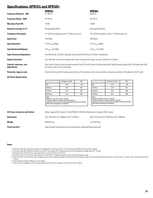
Specifications, <strong>HPR151i</strong> and <strong>HPR181i</strong><br />
<strong>HPR151i</strong> <strong>HPR181i</strong><br />
Frequency Response, -3dB 51-105 Hz 45-95 Hz<br />
Frequency Range, -10dB 43-145 Hz 39-145 Hz<br />
Maximum Peak SPL 133dB 134dB<br />
Nominal coverage, H x V Not applicable (N/A) Not applicable (N/A)<br />
Transducer Description 15” (381mm) transducer with 3” (76mm) voice coil 18” (457mm) transducer with 4” (102mm) voice coil<br />
Amp Power 700 Watts 700 Watts<br />
Input Sensitivity 0.775 V rms (+0dBu) 0.775 V rms (+0dBu)<br />
Input Headroom/Clipping 10 V rms (+22.2dBu) 10 V rms (+22.2dBu)<br />
Input Connectors/Impedance Two XLR female, 22k Ohm, balanced, left and right (L+R) inputs (11k Ohms unbalanced)<br />
Output Connectors Four XLR male: two wired in parallel with Input connector (full range), two post-100 Hz low-cut filters<br />
Controls, Indicators, and Gain control, Polarity switch (normal/reverse), Front LED on/off switch, Limit/Clip (red LED), Signal presence (green LED), AC Power (blue LED)<br />
Adjustments AC Power switch, AC circuit breaker<br />
Protection, Agency certs. Thermal limiting, On/Off muting, power limiting, DC protection, short circuit protection, ultrasonic protection, RF protection, UL/CE listed<br />
AC Power Requirements<br />
AC Power Connector and Cordset Factory supplied IEC cordset: 9’ (3m) #18AWG 120V North American or European 230V cordset<br />
Dimensions 25.6” (651mm) x 22” (559mm) x 20.7” (525mm) 28.6” (727mm) x 23.5” (597mm) x 22.9” (582mm)<br />
Weight 98 lb/44.5 kg 127 lb/57.6 kg<br />
Finish and Grill Wear-resistant textured paint finish with powder-coated perforated steel grill<br />
Notes:<br />
1- Maximum Peak SPL: Calculated by adding the loudspeaker’s sensitivity (1W at 1m) to the peak power (dBw) of the amplifier provided.<br />
2- Directivity Index (DI): Difference between on-axis SPL and average SPL (considering all axes) for the specified coverage range. DI= 10 log Q<br />
3- Directivity Factor (Q): Directivity index expressed as a power ratio Q=10 exp DI/10<br />
4- Amplifier Power: The maximum sustained power at less than 1% clipping, averaged over the intended frequency range,<br />
5- Input Sensitivity: The sine-wave input voltage required to reach amplifier clipping, measured within the frequency range used to determine Maximum Peak SPL, with the gain on “normal” and no gain reduction due to<br />
limiting.<br />
6- Input Headroom/Clipping: Maximum input voltage.<br />
7- Input Connector/Impedance: RF shunt capacitance should not reduce impedance by more than 30% at 20k Hz.<br />
23