

DETECTEUR DE POSITION POUR "PROFIL T ... - ASCO Numatics
DETECTEUR DE POSITION POUR "PROFIL T ... - ASCO Numatics
DETECTEUR DE POSITION POUR "PROFIL T ... - ASCO Numatics

You also want an ePaper? Increase the reach of your titles
YUMPU automatically turns print PDFs into web optimized ePapers that Google loves.
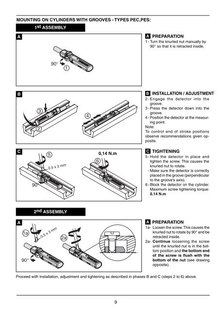
MOUNTING ON CYLIN<strong>DE</strong>RS WITH GROOVES - TYPES PEC,PES:<br />
A<br />
B<br />
C<br />
A<br />
1a<br />
90°<br />
1st ASSEMBLY<br />
2<br />
90°<br />
3<br />
5<br />
90°<br />
0,5 x 3 mm<br />
0,5 x 3 mm<br />
1<br />
2nd ASSEMBLY<br />
2a<br />
4<br />
6<br />
0,14 N.m<br />
9<br />
A PREPARATION<br />
1 - Turn the knurled nut manually by<br />
90° so that it is retracted inside.<br />
B INSTALLATION / ADJUSTMENT<br />
2 - Engage the detector into the<br />
groove.<br />
3 - Press the detector down into the<br />
groove.<br />
4 - Position the detector at the measuring<br />
point.<br />
Note:<br />
To control end of stroke positions<br />
observe recommendations given opposite.<br />
C TIGHTENING<br />
5 - Hold the detector in place and<br />
tighten the screw. This causes the<br />
knurled nut to rotate.<br />
- Make sure the detector is correctly<br />
placed in the groove (perpendicular<br />
to the groove’s axis).<br />
6 - Block the detector on the cylinder.<br />
Maximum screw tightening torque:<br />
0.14 N.m<br />
A PREPARATION<br />
1a- Loosen the screw. This causes the<br />
knurled nut to rotate by 90° and be<br />
retracted inside.<br />
2a- Continue loosening the screw<br />
until the knurled nut is in the bottom<br />
position and the bottom end<br />
of the screw is fl ush with the<br />
bottom of the nut (see drawing<br />
opposite).<br />
Proceed with Installation, adjustment and tightening as described in phases B and C (steps 2 to 6) above.


