

DETECTEUR DE POSITION POUR "PROFIL T ... - ASCO Numatics
DETECTEUR DE POSITION POUR "PROFIL T ... - ASCO Numatics
DETECTEUR DE POSITION POUR "PROFIL T ... - ASCO Numatics

You also want an ePaper? Increase the reach of your titles
YUMPU automatically turns print PDFs into web optimized ePapers that Google loves.
MOUNTING RECOMMENDATIONS<br />
Make sure that the power cable for the detector is not subject to tension<br />
or torsional stress throughout its lifetime.<br />
- Avoid using cables which are not long enough.<br />
- Do not pull on the cables.<br />
- Do not fold the cables.<br />
- Observe a minimum bending radius of 15 mm in static assembly.<br />
- Do not pinch the cables when using a retaining ring plier. The minimum<br />
tightening torque must be observed (for cable dia. 2 – 2.5 mm).<br />
- Do not mount position detectors near to ferromagnetic or intense electromagnetic<br />
fi elds (solenoid coil, soldering tongs etc.).<br />
- Do not use the PVC cable in oily environments or with incompatible solvents<br />
(consult us if necessary). Clean with an alcaline solution (soapy<br />
water).<br />
Min.<br />
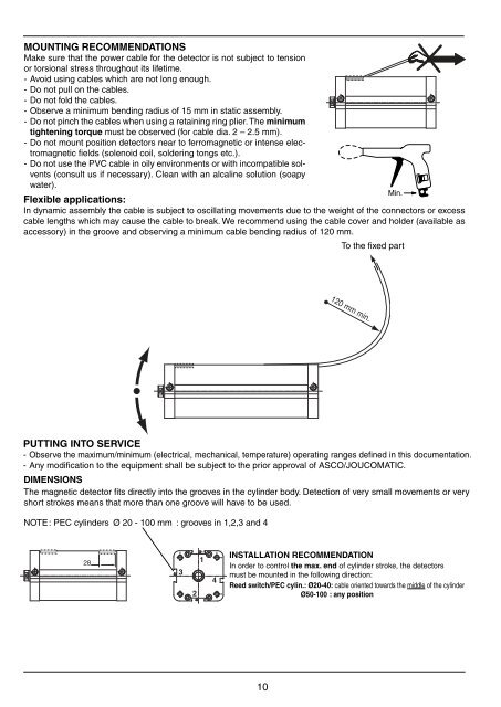
Flexible applications:<br />
In dynamic assembly the cable is subject to oscillating movements due to the weight of the connectors or excess<br />
cable lengths which may cause the cable to break. We recommend using the cable cover and holder (available as<br />
accessory) in the groove and observing a minimum cable bending radius of 120 mm.<br />
To the fi xed part<br />
PUTTING INTO SERVICE<br />
- Observe the maximum/minimum (electrical, mechanical, temperature) operating ranges defi ned in this documentation.<br />
- Any modifi cation to the equipment shall be subject to the prior approval of <strong>ASCO</strong>/JOUCOMATIC.<br />
DIMENSIONS<br />
The magnetic detector fi ts directly into the grooves in the cylinder body. Detection of very small movements or very<br />
short strokes means that more than one groove will have to be used.<br />
NOTE : PEC cylinders Ø 20 - 100 mm : grooves in 1,2,3 and 4<br />
28<br />
3<br />
2<br />
1<br />
4<br />
INSTALLATION RECOMMENDATION<br />
In order to control the max. end of cylinder stroke, the detectors<br />
must be mounted in the following direction:<br />
Reed switch/PEC cylin.: Ø20-40: cable oriented towards the middle of the cylinder<br />
Ø50-100 : any position<br />
10<br />
120 mm min.


