You also want an ePaper? Increase the reach of your titles
YUMPU automatically turns print PDFs into web optimized ePapers that Google loves.
EN<br />
EN<br />
The 675 is equipped with removable cable<br />
stops that can be used for the assembly of<br />
electrical units.<br />
Originally, the cable stops were intended for<br />
fitting a mechanical unit.<br />
For an electrical unit one must use the specific<br />
cable stops supplied with the frame.<br />
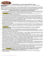
fig. f<br />
Retaining spring<br />
Adjusting screw<br />
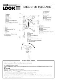
ASSEMBLY<br />
REMOVABLE cable stops<br />
Frame<br />
Cable stop<br />
1. Ensure that the cable stop is in the open<br />
position.<br />
2. Position the cable stop in its housing,<br />
against the <strong>com</strong>posite wall of the frame (Fig. f).<br />
3. Lightly tighten the adjusting screw (1 Nm)<br />
until the housing retainer is in its housing (Fig.<br />
g).<br />
Important: Excessive tightening of the<br />
adjusting screw may damage the screw<br />
threads or the retaining spring. The cable<br />
stops’ stability may be impacted.<br />
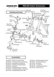
fig. g<br />
Cable stop in position<br />
in its housing<br />
DISMANTLING<br />
Remove the housing possibly lodged in the cable<br />
stop.<br />
1. Undo the adjusting screw until the cable stop<br />
and the housing <strong>com</strong>e free of each other.<br />
2. Extract the cable stop. If the stop resists<br />
extraction, undo the adjusting screw further.<br />
Important: The end piece of the<br />
adjusting screw is flattened so as to<br />
avoid disengagement of the retaining<br />
spring when loosening. Do not force the<br />
loosening or the retaining spring may<br />
disengage and damage its threads or<br />
those of the adjusting screw. It may also<br />
impact the positioning of the end cap or its<br />
disengagement.<br />
ASSEMBLY OF THE<br />
REAR BRAKE WIRE<br />
The rear brake wire runs without housing inside<br />
the horizontal tube.<br />
1. Remove the cable stop for the rear break<br />
(located at the end of the horizontal tube).<br />
2. Place the rear break housing in the housing<br />
located at the beginning of the horizontal tube.<br />
3. Run the brake wire so that it exits via the<br />
housing of the break located at the end of the<br />
horizontal tube.<br />
4. Re-fit the housing located at the end of the<br />
horizontal tube.<br />
Thanks to its cable stops, your 675 frame can be mounted with a mechanical or electrical unit (DI2 or<br />
EPS).<br />
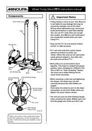
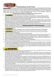
ASSEMBLY OF SHIMANO DI2 & CAMPAGNOLO EPS ROUTING<br />
For more information about the installation of the DI2 or EPS routing systems, please see the<br />
manufacturer’s instructions. (Example of assembly with the battery under the diagonal tube. Other<br />
assemblies are possible: read the construction instructions.)<br />
DI2 / EPS<br />
cable stop<br />
Optional DI2 / EPS drill hole for<br />
assembly of the battery on the<br />
diagonal tube<br />
DI2 / EPS<br />
drill hole<br />
Main connector (insert<br />
perforated housing)<br />
DI2 / EPS<br />
cable stop<br />
DI2 / EPS drill hole, assembly<br />
of the re<strong>com</strong>mended battery<br />
under the crank<br />
24 25