


Create successful ePaper yourself
Turn your PDF publications into a flip-book with our unique Google optimized e-Paper software.
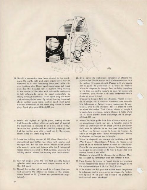
(12)<br />
20. Should a connector have been riveted to the crankcase,<br />
the earth, light and short circuit wires may be<br />
fastened to it. Pull insulating hose and cable clip<br />
over ignition wire. Mount spark plug hood, but make<br />
sure that the threaded rob is pushed firmly exactly<br />
in the centre of the wire until noticeable resistance<br />
is felt. Afterwards, screw in hood completely by<br />
slowly turning it clockwise. Insert spark plug into hood<br />
and put on cylinder head. By quickly turning fan wheel<br />
check ignition once more. Ignition spark must jump<br />
between electrodes of the spark plug. Screw in spark<br />
plug. Spark plug gap 0,016-0,020 ins.<br />
21. Mount and tighten air guide plate, making certain<br />
that the profile rubber, which serves to seal off against<br />
the crankcase, is installed (if it is not, the air circulation<br />
for the cylinder will not function properly), and<br />
that the ignition wire clip is held fast by the proper<br />
screw. Snap on spark plug hood.<br />
22. Screw on holding device W 116 (See illustration 1,<br />
dismantling) and tighten fan wheel with washer and<br />
hexagon nut. Put on dust cover. Mount catch piece<br />
with security plate and tighten with the 3 hexagonal<br />
recess screws provided for that purpose. Unscrew the<br />
holding device. Mount fan housing with recoil-starter.<br />
23. Test-run engine. After the first test possibly tighten<br />
cylinder head once more with torque wrench at 18.1<br />
ftlb. (2,5 kpm).<br />
24. Should the engine not be used for a longer time period,<br />
preserve the interior by means of the preservation<br />
funnel W 53. (Consult our preservation regulations).<br />
20. Si le carter du vilebrequin comporte un attache-fils,<br />
y placer les fils de masse, le fil d'alimentation et le fil<br />
du rupteur (fil coupe-circuit). Passer le fil de bougie<br />
par Ia gaine de protection et Ia bride de fixation.<br />
Visser le chapeau de bougie. Pour ce faire, introduire<br />
Ia vis bien au centre jusqu'a ce que l'on sente une<br />
resistance, puis tourner le chapeau lentement vers Ia<br />
droite et visser a fond.<br />
Engager Ia bougie dans son chapeau. Placer le culot<br />
de Ia bougie sur Ia culasse. Controler une nouvelle<br />
fois l'allumage en faisant tourner rapidement le ventilatour.<br />
Une bonne etincelle doit se produire entre<br />
les deux electrodes. Tout d'abord Visser Ia bougie a<br />
Ia main dans Ia culasse, puis Ia bloquer a !'aide d'une<br />
cle et d'une broche. Pont d'allumage de Ia bougie:<br />
0.016-0.020 pes.<br />
21. Monter le capot guide d'air, bien s'assurer que le joint<br />
en caoutchouc moule qui sert a l'ajuster contre le<br />
carter du vi lebrequin est en place (sinon Ia circulation<br />
cl'air vers le cylindre ne se fera pas correctement.)<br />
Le fixer; ce faisant, serrer Ia bride de fixation du<br />
cable de bougie sous l'ecrou correspondant. Mettre<br />
le chapeau de boug1e sur Ia bougie.<br />
22. Visser le dispositif de blocage du ventilateur W 116<br />
(Voir Figure 1 Demontage). A !'aide de l'ecrou a six<br />
pans et de Ia rondelle serrer le rotor du ventilateur.<br />
Placer Ia tole pare-poussiere. Monter l'entraineur avec<br />
sa plaque de protection et le fixer a !'aide des trois<br />
ecrous fournis a cet effet.<br />
Devisser le dispositif de blocage du ventilateur. Monter<br />
le capot du ventilateur avec son lanceur a main.<br />
23. Faire tourner le moteur a l'essai. Apres les premiers<br />
essais resserrer les ecrous de culasse au moyen de Ia<br />
cle dynamometrique a 18.1 pi. lb (2,5 kpm).<br />
24. Si le moteur ne doit pas ~tre utilise avant longtemps<br />
le preserver contre Ia corrosion au moyen de l'entonnoir<br />
special W 53 (voir nos conseils de protection<br />
anti-corrosif avant stockage).<br />
10


