

69-2413EF-01 - Humidifier - Jackson Systems
69-2413EF-01 - Humidifier - Jackson Systems
69-2413EF-01 - Humidifier - Jackson Systems

Create successful ePaper yourself
Turn your PDF publications into a flip-book with our unique Google optimized e-Paper software.
<strong>Humidifier</strong><br />
PROFESSIONAL INSTALLATION GUIDE<br />
GETTING<br />
STARTED<br />
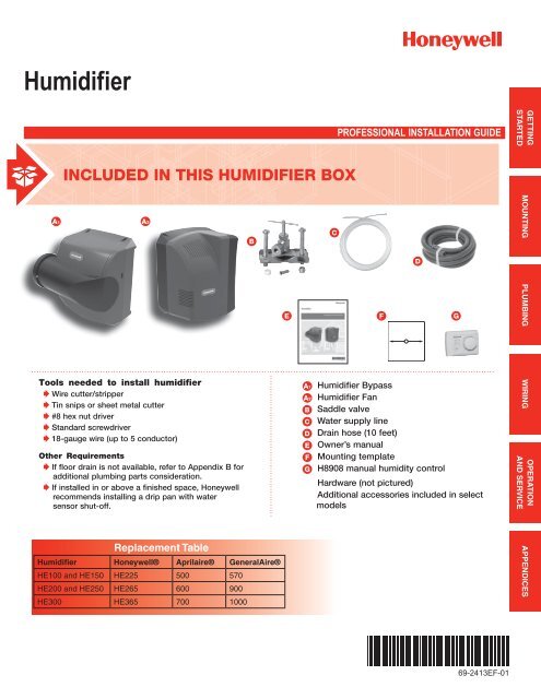
INCLUDED IN THIS HUMIDIFIER BOX<br />
A1<br />
Tools needed to install humidifier<br />
Wire cutter/stripper<br />
Tin snips or sheet metal cutter<br />
#8 hex nut driver<br />
Standard screwdriver<br />
18-gauge wire (up to 5 conductor)<br />
A2<br />
Other Requirements<br />
If floor drain is not available, refer to Appendix B for<br />
additional plumbing parts consideration.<br />
If installed in or above a finished space, Honeywell<br />
recommends installing a drip pan with water<br />
sensor shut-off.<br />
Replacement Table<br />
<strong>Humidifier</strong> Honeywell® Aprilaire® GeneralAire®<br />
HE100 and HE150 HE225 500 570<br />
HE200 and HE250 HE265 600 900<br />
HE300 HE365 700 1000<br />
E<br />
A1<br />
A2<br />
E<br />
F<br />
G<br />
F<br />
<strong>Humidifier</strong> Bypass<br />
<strong>Humidifier</strong> Fan<br />
Saddle valve<br />
Water supply line<br />
Drain hose (10 feet)<br />
Owner’s manual<br />
Mounting template<br />
H8908 manual humidity control<br />
Hardware (not pictured)<br />
Additional accessories included in select<br />
models<br />
G<br />
OPERATION<br />
MOUNTING PLUMBING WIRING APPENDICES<br />
AND SERVICE<br />
<strong>69</strong>-<strong>2413EF</strong>-<strong>01</strong>
<strong>Humidifier</strong><br />
GETTING STARTED<br />
WIRING<br />
Safety Definitions and Precautions . . . . . . . . . . . . . . 2 Before Wiring <strong>Humidifier</strong> . . . . . . . . . . . . . . . . . . . . . 15<br />
What to Expect From Your <strong>Humidifier</strong> . . . . . . . . . . . . 3 STEP ONE: Remove the <strong>Humidifier</strong> Cover . . . . 15<br />
Important Installation Requirements . . . . . . . . . . . . . 4 STEP TWO: Understand the Wiring Terminals . . 15<br />
STEP THREE: Understand the DIP Switches . . 16<br />
MOUNTING<br />
STEP FOUR: Install the Transformer<br />
Choosing a Mounting Method . . . . . . . . . . . . . . . . . . 5 (Bypass Models Only) .................. 16<br />
STEP ONE: Select the Mounting Location ...... 6 STEP FIVE: Wiring <strong>Humidifier</strong> .............. 16<br />
STEP TWO: Install Mounting<br />
Wiring Configuration: Advanced Models<br />
Template to the Duct .................... 6 (HE150/HE250/HE300) ...................... 17<br />
Bypass Model Installation . . . . . . . . . . . . . . . . . . . . . 7 Wiring Configuration: Basic Models<br />
STEP THREE: Configure<br />
(HE100/HE200) ............................ 19<br />
<strong>Humidifier</strong> Bypass ...................... 7<br />
STEP FOUR: Installation . . . . . . . . . . . . . . . . . . . 8 OPERATION AND SERVICE<br />
STEP FIVE: Bypass Duct Installation .......... 9 Startup and Checkout . . . . . . . . . . . . . . . . . . . . . . . 21<br />
Fan Model Installation . . . . . . . . . . . . . . . . . . . . . . . 10 Routine Maintenance ........................ 22<br />
STEP THREE: Installation . . . . . . . . . . . . . . . . . 10 Troubleshooting ............................ 23<br />
<strong>Humidifier</strong> Control Installation . . . . . . . . . . . . . . . . . 11<br />
OPTION ONE: Duct Installation<br />
APPENDICES<br />
H8908 Humidistat . . . . . . . . . . . . . . . . . . . . . 11 A: Specifications . . . . . . . . . . . . . . . . . . . . . . . . . . . 24<br />
OPTION TWO: Remote Installation<br />
B: Advanced Draining . . . . . . . . . . . . . . . . . . . . . . . 25<br />
H8908 Humidistat . . . . . . . . . . . . . . . . . . . . . 12 C: Parts List ............................... 26<br />
PLUMBING<br />
Water Supply and Drain Connections . . . . . . . . . . . 13<br />
STEP ONE: Connect the Water Supply ....... 13<br />
STEP TWO: Tap into a Water Line ........... 13<br />
STEP THREE: Connect to the Water Drain . . . . 14<br />
?<br />
NEED HELP? For assistance with this product please visit http://yourhome.honeywell.com<br />
or call Honeywell Customer Care toll-free at 1-800-468-1502.<br />
GETTING<br />
STARTED<br />
OPERATION<br />
MOUNTING PLUMBING WIRING APPENDICES<br />
AND SERVICE<br />
Read and save these instructions.<br />
® U.S. Registered Trademark. Patents pending. Copyright © 2<strong>01</strong>0 Honeywell International Inc. All rights reserved.<br />
<strong>Humidifier</strong> <strong>69</strong>-<strong>2413EF</strong>—<strong>01</strong><br />
1
Safety Definitions and Precautions<br />
GETTING<br />
STARTED<br />
Safety Definitions<br />
These safety terms identify information you must read prior to installing or operating the humidifier.<br />
CAUTION: Indicates a hazardous situation which, if not avoided, could cause bodily injury<br />
or property damage.<br />
WARNING: Indicates a hazardous situation which, if not avoided, could result in death or serious injury.<br />
Safety Precautions<br />
Make sure you read and understand the following safety hazards before installing, using, or working with the<br />
humidifier:<br />
CAUTION: Voltage Hazard.<br />
Can cause electrical shock or equipment damage.<br />
Disconnect HVAC equipment and any electrical outlet being used for the humidifier installation.<br />
WARNING: Electrocution and Water Hazard.<br />
Can cause death, blindness, and water damage to the home and HVAC Equipment.<br />
CAUTION: Condensation, Fire, and Freezing Water Hazard.<br />
Can cause failure of fan or limit control or result in water damage to home.<br />
2<br />
<strong>Humidifier</strong> <strong>69</strong>-<strong>2413EF</strong>—<strong>01</strong>
What to Expect From Your <strong>Humidifier</strong><br />
The installer should review these points with the homeowner and answer any questions they have before leaving<br />
the job site.<br />
• Achieving Humidity Setpoint. It may take up to a week of continuous operation to achieve the humidity<br />
setpoint, especially if the home is dry when the humidifier is installed. This also depends on such factors as<br />
weather, size of home, furnishings in the home, and insulation.<br />
GETTING<br />
STARTED<br />
• Ideal Humidity. Home building industry experts cite 35% relative humidity as ideal for comfort and<br />
safeguarding the home during the typical dry season. Homeowners can adjust to their own comfort or until<br />
there is condensation on the windows. Lower the setpoint if condensation appears.<br />
• Unit Not Humidifying. If the humidifier is not running but the humidity is below the setpoint, the humidity<br />
control may have a frost protection setting to prevent window condensation from appearing.<br />
• Home Ventilation. Excessive ventilation sends moist air outside and replaces it with dry air. This can make it<br />
hard to maintain the humidity setpoint. If installing a ventilator, use a solution that retains moisture. An Energy<br />
Recovery Ventilator (ERV) is recommended.<br />
• Cleaning Requirements. At least once per year it is recommended to change the humidifier pad and clean<br />
the water trays of the humidifier. See Operation and Service section for details.<br />
• Energy Consumption. It is important to explain that with any humidification solution there is a cost<br />
associated with converting water to humidity. The humidifier utilizes the air heat and air flow in your ducting to<br />
make this conversion, which has gas and/or electric costs that depend on your HVAC system type and setup.<br />
<strong>Humidifier</strong> <strong>69</strong>-<strong>2413EF</strong>—<strong>01</strong> 3
Important Installation Requirements<br />
GETTING<br />
STARTED<br />
Failure to comply with these requirements will result in voided warranty, improper installation, and<br />
service callbacks.<br />
Personal Safety<br />
• Wear safety glasses while installing the humidifier.<br />
• Do not cut into any air conditioning or electrical line.<br />
• Follow professional safety standards and all local regulations for plumbing, electrical, and mechanical<br />
considerations.<br />
Mounting Location<br />
• Mount the humidifier in a level position to avoid water damage and ensure maximum output.<br />
• Location must have access to a water line, drain, and power.<br />
• Do not install the humidifier where the ambient temperature is lower than 34°F (1.1°C) or higher than 90°F<br />
(40°C).<br />
• Mounting area must be strong enough to support humidifier weight (up to 16 lbs [Fan] or 10 lbs [Bypass]).<br />
• Do not mount directly to ductboard.<br />
• If used near a pool or spa, make sure the humidifier can not fall into the water or be splashed.<br />
• Ensure that the top and bottom covers of the humidifier can be removed and that the pad is accessible from<br />
the chosen location.<br />
Water Supply and Drainage<br />
• Consult local plumbing codes for drain size, material, and maximum temperature allowed.<br />
If Replacing an Old Bypass <strong>Humidifier</strong><br />
The humidifier is not identical in size and shape to other Honeywell bypass humidifiers. Before performing a<br />
retrofit installation, you might need to:<br />
• Dry-fit the humidifier to the existing ducting, plumbing, and wiring before fastening it to the duct to ensure that<br />
the existing connections will reach the humidifier.<br />
• If the duct opening of the old humidifier is not the right size for the humidifier, choose a new location or cover<br />
the old opening with a piece of sheet metal and cut a new opening specifically for the humidifier using the<br />
template provided.<br />
Replacement Table<br />
<strong>Humidifier</strong> Honeywell® Aprilaire® GeneralAire®<br />
HE100 and HE150 HE225 500 570<br />
HE200 and HE250 HE265 600 900<br />
HE300 HE365 700 1000<br />
4<br />
<strong>Humidifier</strong> <strong>69</strong>-<strong>2413EF</strong>—<strong>01</strong>
Choosing a Mounting Method<br />
Whether you purchased a Bypass or Fan humidifier will determine how your humidifier will be installed:<br />
Which humidifier do you have?<br />
Bypass:<br />
Bypass humidifiers use the pressure difference<br />
between the supply and return to move duct<br />
air through the humidifier. Access to both the<br />
supply and return are required.<br />
Fan:<br />
Fan humidifiers use the fan inside the humidifier<br />
to pull duct air through the humidifier. Access to<br />
only the supply or the return is required.<br />
MOUNTING<br />
MCR29871<br />
MCR29929<br />
Before beginning Mounting:<br />
I have confirmed local codes for proper plumbing practices.<br />
I have chosen an installation location that meets the requirements on page 4.<br />
<strong>Humidifier</strong> <strong>69</strong>-<strong>2413EF</strong>—<strong>01</strong> 5
STEP ONE: Select the Mounting Location<br />
1<br />
Choose a location that has access to a water supply<br />
pipe. Cold or hot water can be used.<br />
Select a vertical or horizontal surface on the HVAC<br />
duct work, with adequate space clearances,<br />
where the humidifier can be mounted. For bypass<br />
installation, access to both the return and supply are<br />
MOUNTING<br />
2<br />
2<br />
3<br />
required. Both humidifier models can be mounted to<br />
either the supply or the return.<br />
Location must also have access to 120 VAC power.<br />
For the HE300 Fan humidifier, the power cord is 6 feet<br />
long.<br />
4<br />
MCR29877<br />
Ensure the location is near a drain. Consult local<br />
plumbing codes for proper drainage. If no main<br />
floor drain is available, see “Appendix B: Advanced<br />
Draining.”<br />
STEP TWO: Install Mounting Template to the Duct<br />
Position the template on the duct.<br />
• Make sure the template is level and in the desired<br />
position on the duct.<br />
1<br />
FAN<br />
BYPASS<br />
2<br />
1-3/4<br />
(44)<br />
1/2<br />
(13)<br />
Ensure proper clearances from the air-conditioning<br />
coil inside the duct.<br />
NOTE: The HE300 Fan model extends into the duct<br />
4<br />
3<br />
A-COIL<br />
1-3/4 inch. Bypass models extend into the duct 1/2<br />
inch. Ensure clearance inside the duct.<br />
• For best performance, maintain at least 24 inches<br />
M29873<br />
downstream of open air space inside the duct.<br />
M29874<br />
Use a marker to trace the template outline onto the<br />
duct, then remove the template.<br />
Cut the sheet metal, following the template outline.<br />
6<br />
<strong>Humidifier</strong> <strong>69</strong>-<strong>2413EF</strong>—<strong>01</strong>
If you are installing HE300 Fan model, proceed to page 10.<br />
Bypass Model Installation<br />
STEP THREE: Configure <strong>Humidifier</strong> Bypass<br />
1<br />
Configure the humidifier bypass outlet to the side that<br />
best fits the application.<br />
1<br />
If the bypass needs to be on the other side, remove<br />
the top and bottom covers<br />
MCR29875<br />
Unplug the damper wire and plug in on the other side<br />
(HE150/HE250 only).<br />
MOUNTING<br />
2<br />
3<br />
3<br />
2<br />
Pull the bypass clamps apart from center to remove<br />
the bypass; snap it back into place with the outlet on<br />
the desired side.<br />
MCR29876<br />
Ensure that the pad is accessible. The handle of<br />
the pad holder and side panel of the humidifier can<br />
be switched so the pad holder can be removed<br />
(opposite side of the bypass duct opening).<br />
4<br />
To remove the handle for the pad holder, slide it<br />
toward the back of the humidifier, then pull it away<br />
from the humidifier.<br />
To remove the opposite side panel, place a<br />
screwdriver into the two slots on the back of the<br />
humidifier, and pop the panel off.<br />
5<br />
Snap the pad holder handle and side panel back into<br />
place in the desired configuration.<br />
MCR29946<br />
<strong>Humidifier</strong> <strong>69</strong>-<strong>2413EF</strong>—<strong>01</strong> 7
Bypass Model Installation<br />
STEP FOUR: Mounting<br />
Secure the support hooks on Bypass models to the<br />
bottom lip of the hole.<br />
1<br />
Push the top of the humidifier back against the duct.<br />
MOUNTING<br />
2<br />
Verify the humidifier is level and fasten the humidifier<br />
to the duct using two self-drilling sheet metal screws<br />
provided.<br />
MCR29870<br />
8<br />
<strong>Humidifier</strong> <strong>69</strong>-<strong>2413EF</strong>—<strong>01</strong>
Bypass Model Installation<br />
STEP FIVE: Bypass Duct Installation<br />
1<br />
2<br />
On the duct opposite the humidifier Bypass install, cut<br />
a 6-in. diameter duct hole.<br />
• If the humidifier is on the supply duct, the 6-in.<br />
diameter hole should be on the return.<br />
• If the humidifier is on the return duct, the 6-in.<br />
diameter hole should be on the supply.<br />
Secure a 6-in. round duct starter collar into the 6-in.<br />
duct hole.<br />
MOUNTING<br />
MCR29933<br />
1<br />
2<br />
Use rigid or aluminized flexible 6-in. duct to connect<br />
the starter collar to the humidifier bypass port.<br />
Secure the duct to the humidifier port with self-drilling<br />
sheet metal screws using the pre-drilled holes on the<br />
bypass port. For added seal, wrap sheet metal tape<br />
around the duct to port connection point.<br />
2<br />
MCR29878<br />
Bypass mounting is complete. Go to page 11.<br />
Before proceeding to the next step:<br />
I secured the humidifier to the duct as instructed.<br />
<strong>Humidifier</strong> <strong>69</strong>-<strong>2413EF</strong>—<strong>01</strong> 9
Fan Model Installation<br />
STEP THREE: Mounting<br />
1<br />
Slide the Fan model evenly into the duct hole. Verify<br />
the humidifier is level.<br />
Fasten the humidifier to the duct using four self-drilling<br />
sheet metal screws provided.<br />
MOUNTING<br />
3<br />
2<br />
Do not plug the humidifier in yet.<br />
MCR29934<br />
10<br />
<strong>Humidifier</strong> <strong>69</strong>-<strong>2413EF</strong>—<strong>01</strong>
<strong>Humidifier</strong> Control Installation<br />
OPTION ONE: Duct Installation of H8908 Humidistat (provided)<br />
If a different control is being used, refer to installation instructions provided with that control.<br />
RETURN<br />
AIR<br />
ALTERNATE LOCATION<br />
1<br />
RETURN<br />
AIR<br />
Choose a location on the duct.<br />
6 in. (152 mm)<br />
MINIMUM<br />
15 in. (381 mm)<br />
MINIMUM<br />
BEST<br />
LOCATION<br />
RETURN AIR DUCT<br />
M133<strong>69</strong><br />
MOUNTING<br />
2<br />
Apply sticker template to duct and drill holes for<br />
mounting screws. Cut along the dotted line of the<br />
template with metal shears or tin snips.<br />
M24800<br />
3<br />
Remove the base bracket from the humidistat. Slide<br />
the black gasket onto the base bracket.<br />
Secure the base bracket to the duct.<br />
Secure to the duct with four 1-in. (25 mm)<br />
screws (provided).<br />
4<br />
M24733<br />
M29879<br />
<strong>Humidifier</strong> <strong>69</strong>-<strong>2413EF</strong>—<strong>01</strong> 11
<strong>Humidifier</strong> Control Installation<br />
OPTION TWO: Remote Installation of H8908 Humidistat (provided)<br />
If a different control is being used, refer to installation instructions provided with that control.<br />
1<br />
Choose a location in the living area. Select a location<br />
clear of drafts or excessive humidity. Avoid mounting<br />
near doors or windows, or in bathrooms or kitchens.<br />
MOUNTING<br />
M29952<br />
2<br />
2<br />
Cut 1-in. diameter wire hole in wall.<br />
Run two-fan, low-voltage wire to the mounting location<br />
in the living area.<br />
M24721<br />
3<br />
Remove the base bracket from the humidistat.<br />
M29948<br />
Secure the base bracket to the remote location with<br />
two 1-in. (25 mm) screws (provided).<br />
4<br />
M29949<br />
12<br />
<strong>Humidifier</strong> <strong>69</strong>-<strong>2413EF</strong>—<strong>01</strong>
Water Supply and Drain Connections<br />
STEP ONE: Connect the Water Supply<br />
Use hot or cold water.<br />
1<br />
Cut the water line so it reaches from the humidifier to<br />
the main water supply tap<br />
Insert the water line into the humidifier supply fitting.<br />
Insert it fully, and apply modest pull pressure to<br />
ensure a tight fit.<br />
2<br />
MCR29880<br />
PLUMBING<br />
STEP TWO: Tap into a Water Line<br />
T-fitting<br />
Manual Shutoff<br />
Valve<br />
Water Supply<br />
Line<br />
Saddle Valve<br />
M29605<br />
• Consult local codes for proper plumbing.<br />
• Use the saddle valve provided or a T-fitting and<br />
manual shutoff valve to tap into the water line.<br />
• Refer to the literature included with the valve you<br />
chose and the local plumbing codes. Use proper<br />
technique for the valve.<br />
• Connect the other end of the humidifier water line<br />
to the water valve.<br />
<strong>Humidifier</strong> <strong>69</strong>-<strong>2413EF</strong>—<strong>01</strong> 13
STEP THREE: Connect to the Water Drain<br />
1<br />
2<br />
3<br />
• Consult and follow local plumbing codes for drain<br />
pipe size and flow requirement.<br />
• The ideal installation is directly to the main floor<br />
drain using the rubber hose provided.<br />
• If direct floor drain access is not available, see<br />
“Appendix B: Advanced Draining.”<br />
Connect the 1/2-in. drain hose provided to the drain<br />
fitting on the bottom of the humidifier.<br />
Use the hose clamp provided to secure the drain hose<br />
to the fitting.<br />
PLUMBING<br />
4<br />
MCR29881<br />
Route the drain hose to the floor drain. The hose must<br />
have a continuous downward slope.<br />
Direct the hose outlet into the floor drain. Secure<br />
the hose to reduce the risk of water pooling or<br />
splashing as it drains from the humidifier.<br />
Before proceeding to Wiring:<br />
I have connected the water supply line to the humidifier and the main water tap.<br />
I have installed the drain connection.<br />
I have checked all plumbing connections for leaks.<br />
14<br />
<strong>Humidifier</strong> <strong>69</strong>-<strong>2413EF</strong>—<strong>01</strong>
Before Wiring the <strong>Humidifier</strong><br />
CAUTION: Voltage Hazard.<br />
Be sure the humidifier is not plugged in before beginning wiring.<br />
Before wiring the humidifier:<br />
I understand and will comply with applicable local wiring codes and regulations.<br />
I will read the section “Using the DIP Switches” beginning on the next page.<br />
What humidifier model do I have?<br />
The model number can be found on the bottom of the humidifier.<br />
STEP ONE: Remove the <strong>Humidifier</strong> Cover<br />
Remove the bottom cover.<br />
1a<br />
MCR29950<br />
MCR29935<br />
STEP TWO: Understand the Wiring Terminals (HE150/HE250/HE300 only)<br />
HE150/HE250 Bypass Terminal<br />
Gf: Used to force system fan on when humidity is<br />
needed.<br />
R: Input from system R. Needed to power Gf when<br />
HE300 Fan Terminal<br />
MCR29937<br />
M29936<br />
1b<br />
forcing fan on.<br />
Gt or W: Input from system G or W. Needed to<br />
humidify only during fan or heat calls by system.<br />
HUM: Dry contacts for humidity control.<br />
C: Common. Needed for Gt or W input. Connect to<br />
system C.<br />
Power Out: 24V power for electric controls.<br />
Power In: Power from 15VA transformer on HE150/<br />
HE250 only.<br />
SENSOR: Dry contacts for air proving device.<br />
WIRING<br />
<strong>Humidifier</strong> <strong>69</strong>-<strong>2413EF</strong>—<strong>01</strong> 15
Using the DIP Switches (HE150/HE250/HE300 only)<br />
Two features are configured by DIP settings, which are described inside the humidifier cover.<br />
STEP THREE: Understand the DIP Switches<br />
MCR29882<br />
DIP 1 (Top): This switch looks for inputs from the<br />
HVAC system before allowing humidity. Set to the left,<br />
the humidifier will look for input(s). Set to the right, it<br />
will not.<br />
DIP 2 (Bottom): This switch controls the fan. Set to<br />
the left, the HVAC system controls the fan. Set to the<br />
right, the humidifier will force the fan on when there is<br />
a call for humidity.<br />
STEP FOUR: Install the Transformer (Bypass Models Only)<br />
Install transformer on the outside of a grounded metal junction box using only a 7/8 in. (22 mm) knockout hole.<br />
Place mounting tabs into the knockout hole and firmly tighten the locking screw. Field wiring connections and<br />
grounding means for the transformer and enclosure shall be in accordance with the National Electrical Code<br />
(NEC) and the Canadian Electrical Code (CEC). Connect wires to the 120V side of the transformer.<br />
For HE150 and HE250, the 15V transformer must provide constant power to the 24V IN terminals.<br />
WIRING<br />
STEP FIVE: Wiring the <strong>Humidifier</strong><br />
Use a wiring diagram from the following pages that matches your equipment.<br />
When wiring is complete, run the wires coming out of the humidifier into the wiring clip on the bottom of the<br />
humidifier.<br />
16<br />
<strong>Humidifier</strong> <strong>69</strong>-<strong>2413EF</strong>—<strong>01</strong>
Wiring Configuration: Advanced Models (HE150/HE250/HE300)<br />
Wiring H8908 to humidify only with a call for heat or fan.<br />
H8908<br />
HUMIDIFIER<br />
HE150 (PICTURED), HE250, HE300<br />
30 40<br />
20<br />
50<br />
HUM<br />
GT OR W<br />
G OR W<br />
C<br />
2<br />
10<br />
OFF<br />
60<br />
ON<br />
1<br />
HE150/HE250 USES A 15 VA TRANSFORMER WIRED INTO 24V IN.<br />
HE100/HE200 USES A 10 VA TRANSFORMER WIRED INTO 24V IN.<br />
HE300 USES A LINE CORD PLUG.<br />
POWER IN<br />
1<br />
AFS<br />
AFS<br />
OR<br />
AIR PROVING<br />
DEVICE<br />
3<br />
2<br />
3<br />
CONNECT G TO HUMIDIFY WHEN THERE IS A FAN CALL.<br />
CONNECT W TO HUMIDIFY WHEN THERE IS A HEAT CALL.<br />
NEVER CONNECT BOTH. CONNECT C WHEN USING G OR W.<br />
USE AIR PROVING DEVICE INSTEAD OF THE G/W CONNECTION<br />
TO HUMIDIFY ANY TIME THE FAN IS OPERATING.<br />
MCR29938<br />
Wiring TrueIAQ, VisionPRO IAQ, or Prestige, using the intelligent control to program humidity calls with heat,<br />
cool, or on demand.<br />
HUMIDIFIER<br />
HE150 (PICTURED), HE250, HE300<br />
WIRING<br />
FROM<br />
HUMIDITY<br />
CONTROL<br />
HUM<br />
1<br />
HE150/HE250 USES A 15 VA TRANSFORMER WIRED INTO 24V IN.<br />
HE100/HE200 USES A 10 VA TRANSFORMER WIRED INTO 24V IN.<br />
HE300 USES A LINE CORD PLUG.<br />
POWER IN<br />
1<br />
MCR29939<br />
<strong>Humidifier</strong> <strong>69</strong>-<strong>2413EF</strong>—<strong>01</strong> 17
Wiring Configuration: Advanced Models (HE150/HE250/HE300)<br />
Wiring to force the HVAC system fan on whenever humidity is needed (on demand).<br />
FROM<br />
HUMIDITY<br />
CONTROL<br />
HUM<br />
GF<br />
GT OR W<br />
G (FURNACE)<br />
G (THERMOSTAT)<br />
POWER OUT<br />
24V FOR<br />
ELECTRONIC<br />
HUMIDISTAT<br />
24V OUT<br />
24V OUT<br />
R<br />
R<br />
1<br />
1<br />
ONLY NEEDED IF SYSTEM’S THERMOSTAT DOES NOT ISOLATE Y FROM G.<br />
IF NEEDED, BREAK THE THERMOSTAT G TO SYSTEM G CONNECTION<br />
AND ROUTE THROUGH HUMIDIFIER AS SHOWN.<br />
POWER IN<br />
2<br />
HE150/HE250 USES A 15 VA TRANSFORMER WIRED INTO 24V IN.<br />
HE100/HE200 USES A 10 VA TRANSFORMER WIRED INTO 24V IN.<br />
HE300 USES A LINE CORD PLUG.<br />
2<br />
MCR29940<br />
WIRING<br />
Wiring to force fan on and prove airflow in the duct.<br />
FROM<br />
HUMIDITY<br />
CONTROL<br />
HUM<br />
GF<br />
GT OR W<br />
G (FURNACE)<br />
G (THERMOSTAT)<br />
POWER OUT<br />
24V FOR<br />
ELECTRONIC<br />
HUMIDISTAT<br />
24V OUT<br />
24V OUT<br />
R<br />
R<br />
1<br />
1<br />
ONLY NEEDED IF SYSTEM’S THERMOSTAT DOES NOT ISOLATE Y FROM G.<br />
IF NEEDED, BREAK THE THERMOSTAT G TO SYSTEM G CONNECTION<br />
AND ROUTE THROUGH HUMIDIFIER AS SHOWN.<br />
POWER IN<br />
2<br />
AFS<br />
AFS<br />
AFS<br />
2<br />
HE150/HE250 USES A 15 VA TRANSFORMER WIRED INTO 24V IN.<br />
HE100/HE200 USES A 10 VA TRANSFORMER WIRED INTO 24V IN.<br />
HE300 USES A LINE CORD PLUG.<br />
MCR29941<br />
18<br />
<strong>Humidifier</strong> <strong>69</strong>-<strong>2413EF</strong>—<strong>01</strong>
Wiring Configuration: Basic Models (HE100/HE200)<br />
Wiring H8908 with fan interlock.<br />
H8908<br />
TRANSFORMER<br />
30 40<br />
L1<br />
(HOT)<br />
L2<br />
POWER<br />
SUPPLY<br />
FAN CONTROL<br />
20<br />
10<br />
OFF<br />
50<br />
60<br />
ON<br />
2<br />
1<br />
FURNACE<br />
FAN<br />
MOTOR<br />
1<br />
2<br />
PROVIDE DISCONNECT MEANS AND<br />
OVERLOAD PROTECTION AS REQUIRED.<br />
24 VAC WIRING.<br />
HUMIDIFIER<br />
M29945<br />
Wiring H8908 with 2-speed fan motor.<br />
H8908<br />
WIRING<br />
TRANSFORMER<br />
30 40<br />
L1<br />
(HOT)<br />
L2<br />
1<br />
POWER<br />
SUPPLY<br />
FAN CONTROL<br />
DPST<br />
SWITCHING<br />
RELAY<br />
2<br />
20<br />
10<br />
OFF<br />
50<br />
60<br />
ON<br />
1<br />
2<br />
POWER SUPPLY. PROVIDE DISCONNECT<br />
MEANS AND OVERLOAD PROTECTION AS<br />
REQUIRED.<br />
24 VAC WIRING.<br />
H<br />
C<br />
L<br />
2-SPEED<br />
FAN<br />
MOTOR<br />
HUMIDIFIER<br />
M29942<br />
<strong>Humidifier</strong> <strong>69</strong>-<strong>2413EF</strong>—<strong>01</strong> 19
Wiring Configuration: Basic Models (HE100/HE200)<br />
Wiring H8908 with current-sensing relay.<br />
H8908<br />
30 40<br />
20<br />
50<br />
10<br />
60<br />
OFF ON<br />
2<br />
WATER<br />
SOLENOID<br />
LEAD WIRE<br />
TRANSFORMER<br />
L2<br />
1<br />
L1<br />
(HOT)<br />
CURRENT<br />
SENSING<br />
RELAY<br />
C<br />
LO<br />
HI<br />
1<br />
POWER SUPPLY. PROVIDE DISCONNECT<br />
MEANS AND OVERLOAD PROTECTION AS<br />
REQUIRED.<br />
2<br />
24V WIRING.<br />
HUMIDIFIER<br />
M29943<br />
WIRING<br />
Wiring H8908 in line with air proving device.<br />
H8908<br />
AIR PROVING<br />
DEVICE<br />
20<br />
30 40<br />
50<br />
10<br />
60<br />
2<br />
OFF<br />
ON<br />
TRANSFORMER<br />
L2<br />
1<br />
L1<br />
(HOT)<br />
1<br />
2<br />
POWER SUPPLY. PROVIDE DISCONNECT MEANS<br />
AND OVERLOAD PROTECTION AS REQUIRED.<br />
24V WIRING.<br />
HUMIDIFIER<br />
M29944<br />
20<br />
<strong>Humidifier</strong> <strong>69</strong>-<strong>2413EF</strong>—<strong>01</strong>
Startup and Checkout<br />
When installation is complete, follow the steps below. Make sure the humidifier is running properly before turning<br />
the system over to the homeowner. Once the humidifier is running, day-to-day operation is automatic. The<br />
homeowner can use the control to adjust the humidity levels and turn the humidifier on or off.<br />
Snap the bottom cover into place.<br />
1<br />
Turn on the water supply at the saddle valve or<br />
T-fitting and manual shutoff valve. Water will flow to the<br />
humidifier but will not pass through the pad until the<br />
humidity control is turned on.<br />
2<br />
Plug in the humidifier (HE300) or apply HVAC system<br />
power (HE100/HE150/HE200/HE250)<br />
• On advanced models, the LED lights will blink for<br />
3-5 seconds to verify that there is system power.<br />
4<br />
3<br />
On HE100/HE200, turn the Damper Position knob on<br />
the bypass outlet so that it is parallel to the bypass<br />
outlet. On HE150/HE250, the humidifier does this<br />
automatically. Not applicable for HE300.<br />
5<br />
Turn the humidity control to On.<br />
• If your wiring is configured for operation only with<br />
heat or fan, make the appropriate system demands<br />
to allow humidification.<br />
• Make sure air is blowing through the ductwork with<br />
the humidifier call.<br />
6<br />
MCR29884<br />
The Humidifying light will be solidly on when water is<br />
flowing through the humidifier pad<br />
• On HE150/HE250 models, remove the humidifier’s<br />
top cover to verify water flow through the top tray<br />
and into the pad. Make sure that the damper<br />
rotates open when humidity is on, and rotates<br />
closed when humidity is off.<br />
• On HE300 models, verify water is exiting the drain<br />
hose.<br />
OPERATION<br />
AND SERVICE<br />
Check all water line and drain connections to ensure there are no leaks before leaving the job site.<br />
• Check for leaks immediately after turning the main water supply on, and again after 15 minutes of humidifier<br />
operation.<br />
Turn the setpoint to the homeowner’s desired level when testing is complete. If humidity is not needed, set the<br />
control to Off, and turn the Damper Position knob on the bypass outlet so that it is perpendicular to the bypass<br />
outlet (HE100/HE200 only).<br />
<strong>Humidifier</strong> <strong>69</strong>-<strong>2413EF</strong>—<strong>01</strong> 21
Routine Maintenance<br />
It is recommended that the humidifier pad be replaced once per year. This can be done at the beginning or the<br />
end of the dry season. The humidifier design makes this annual replacement quick and easy, providing one-step<br />
access to the pad.<br />
Bypass:<br />
1a. Pad can be replaced from the side by gripping<br />
the black handle and pulling out, or from the<br />
front by removing the humidifier’s top cover<br />
and rocking the pad forward and out.<br />
<strong>Humidifier</strong> pad might remove from other side<br />
of humidifier, depending on installation.<br />
Fan:<br />
1b. Pad can be replaced from the front by gripping<br />
the black handle and pulling out.<br />
2<br />
25%<br />
1<br />
MCR29886<br />
MCR29885<br />
OPERATION<br />
AND SERVICE<br />
2.<br />
3.<br />
Remove tray on top of the pad, and wipe free any sediment present within the tray.<br />
Replace the old pad with the new, making sure pad is oriented correctly (see pad box). Wipe free any<br />
sediment present inside the pad frame.<br />
4. Reseat the tray on top of the pad with the arrows inside the tray pointing into the duct. Then reinsert the frame<br />
into the humidifier.<br />
5. Afer pad replacement is complete, remove the bottom cover and press the RESET button to reset the<br />
maintenance timer.<br />
22<br />
<strong>Humidifier</strong> <strong>69</strong>-<strong>2413EF</strong>—<strong>01</strong>
Troubleshooting<br />
Problem What To Look For What To Do<br />
Low humidity<br />
Furnace blower not<br />
operating<br />
1.<br />
2.<br />
3.<br />
4.<br />
Reset circuit breaker or check for blown fuse.<br />
Check that the furnace power is on.<br />
Check all external wiring connections.<br />
Check the humidity control setting.<br />
Rapid air changes or<br />
drafts<br />
1.<br />
2.<br />
3.<br />
4.<br />
Keep doors and windows closed.<br />
Close fireplace damper when not in use.<br />
Keep exhaust fan running time to a minimum.<br />
Seal around doors and windows.<br />
High humidity Condensation on walls 1. Turn off humidity control and water until condensation is completely<br />
evaporated.<br />
Heavy condensation on<br />
windows<br />
1.<br />
Turn humidity control down low enough to eliminate condensation<br />
caused by moisture. If moisture persists, more ventilation is needed.<br />
Replace Pad<br />
light is on<br />
(HE150/HE250/<br />
HE300)<br />
This is the yearly<br />
maintenance reminder to<br />
replace the pad inside the<br />
humidifier<br />
1.<br />
2.<br />
Refer to the parts list and replace the pad for your humidifier model.<br />
Once pad is replaced, press the RESET button under the wire cover.<br />
Service light is on<br />
(HE150/HE250)<br />
The damper inside the<br />
bypass has failed to open<br />
completely<br />
1.<br />
2.<br />
3.<br />
4.<br />
Press RESET button under the wire cover.<br />
Verify the damper plug is connected on the side of the humidifier the<br />
bypass outlet is on.<br />
Ensure there is no interference from sheet metal screws that connect<br />
the bypass to ducting.<br />
If fault persists, replace bypass damper motor.<br />
Service light is on<br />
(HE300)<br />
Air proving device has<br />
detected a lack of air<br />
movement<br />
Only possible with DIPs<br />
configured as:<br />
The fan motor has failed<br />
1.<br />
2.<br />
3.<br />
4.<br />
5.<br />
1.<br />
2.<br />
3.<br />
Check wiring to Air Flow Switch.<br />
Confirm DIP switch configuration and wiring on the humidifier is correct.<br />
Check location of Air Flow Switch to ensure it is properly placed in duct<br />
to detect air.<br />
Check switch relays.<br />
If fault persists, replace Air Flow Switch.<br />
Press RESET button under the wire cover.<br />
Unplug the humidifier and plug it back in.<br />
If fault persists, replace motor assembly.<br />
OPERATION<br />
AND SERVICE<br />
Air proving device has<br />
detected a lack of air<br />
movement<br />
Only possible with DIPs<br />
configured as:<br />
1.<br />
2.<br />
3.<br />
4.<br />
5.<br />
Check wiring to Air Flow Switch.<br />
Confirm DIP switch configuration and wiring on the humidifier is correct.<br />
Check location of Air Flow Switch to ensure it is properly placed in duct<br />
to detect air.<br />
Check switch relays.<br />
If fault persists, replace Air Flow Switch.<br />
<strong>Humidifier</strong> <strong>69</strong>-<strong>2413EF</strong>—<strong>01</strong> 23
A: Specifications<br />
Humidifying Capacity<br />
At 120°F (49°C) plenum temperature and 0.20 static pressure<br />
drop across supply and return:<br />
HE100/150: up to 12 gallons per day (gpd)<br />
(46 liters per day [lpd])<br />
HE200/250: up to 17 gpd (65 lpd)<br />
HE300: up to 18 gpd (68 lpd)<br />
Operating Ranges<br />
34ºF–90ºF (1.1ºC–32ºC)<br />
Humidity: 0–95% RH, non-condensing<br />
Drain Fitting<br />
1/2 in. (13 mm) I.D. plastic hose connected directly to drain<br />
fitting on unit.<br />
Humidified Area<br />
HE100/150: Up to 16,000 cubic feet<br />
HE200/250: Up to 20,000 cubic feet<br />
HE300: Up to 24,000 cubic feet<br />
Dimensions<br />
HE100/150: 14.5 in. W x 14 in. H x 10.1 in. D<br />
(368 mm W x 356 mm H x 257 mm D)<br />
HE200/250: 15 in. W x 17.15 in. H x 10.1 in. D<br />
(381 mm W x 436 mm H x 257 mm D)<br />
HE300: 15.5 in. W x 16.8 in. H x 10.3 in. D<br />
(394 mm W x 427 mm H x 262 mm D)<br />
<strong>Humidifier</strong> Pad Dimensions<br />
HE100/150: 9-1/2 in. W x 9-13/16 in. H x 1-1/2 in. D<br />
(241 mm W x 249 mm H x 38 mm D)<br />
HE200/250: 10 in. W x 13 in. H x 1-1/2 in. D<br />
(254 mm W x 330 mm H x 38 mm D)<br />
HE300: 10 in. W x 13 in. H x 1-1/2 in. D<br />
(254 mm W x 330 mm H x 38 mm D)<br />
Electrical Ratings and Tolerances<br />
HE100/200: 24VAC, 60 Hz, 0.5 A maximum<br />
HE150/250: 24VAC, 60 Hz, 0.75 A maximum<br />
HE300: 120VAC, 60 Hz, 1 A maximum<br />
Standards and Approvals (HE100/150/200/250)<br />
• Underwriters Laboratories Inc. Listing: 56 BL.<br />
• Canadian Underwriters Laboratories Inc. Listing: 56 BL.<br />
• Air Conditioning and Refrigeration Institute Tested:<br />
Standard 610.<br />
Standards and Approvals (HE300)<br />
• Underwriters Laboratories Inc.: Listing Pending.<br />
• Canadian Underwriters laboratories Inc.: Listing Pending.<br />
• Air Conditioning and Refrigeration Institute Tested:<br />
Standard 610.<br />
OPERATION<br />
AND SERVICE<br />
Plenum Opening Dimensions<br />
HE100/150: 9-5/16 in. W x 9-7/16 in. H (238 mm W x 241 mm H)<br />
HE200/250: 9-3/4 in. W x 12-5/8 in. H (248 mm W x 321 mm D)<br />
HE300: 13-1/2 in. W x 14-1/16 in. H (343 mm W x 357 mm D)<br />
Bypass Duct Opening Dimensions (HE100/150/200/250)<br />
6 in. (152 mm)<br />
24<br />
<strong>Humidifier</strong> <strong>69</strong>-<strong>2413EF</strong>—<strong>01</strong>
Option 2: Plumbing to a dedicated trap.<br />
1/2 IN. MNPT X SWEAT<br />
1/2 IN. FNPT X 1-1/2 IN. PVC<br />
VENTED PER<br />
LOCAL CODE<br />
1/2 IN. (MINIMUM) PVC PIPE<br />
1-1/2 IN. PVC<br />
1/2 IN. MNPT X 1/2 IN. CPVC<br />
1/2 IN. FNPT X 1-1/2 IN. PVC<br />
ALL PLASTIC PIPE<br />
JOINTS ARE WELDED<br />
HOSE CLAMP<br />
1/2 IN. BARB X 1/2 IN. MNPT<br />
1/2 IN. FNPT X 1-1/2 IN. PVC<br />
1-1/2 IN. MINIMUM TRAP<br />
(OR SIZE PER LOCAL CODE)<br />
SIZE TO FIT PUMP OUTPUT<br />
Option 4: Plumbing to sink trap.<br />
1/2 IN. MNPT X SWEAT<br />
1/2 IN. FNPT X 1-1/2 IN. PVC<br />
1/2 IN. (MINIMUM)<br />
PVC PIPE<br />
1-1/2 IN. PVC<br />
1/2 IN. MNPT X 1/2 IN. CPVC<br />
1/2 IN. FNPT X 1-1/2 IN. PVC<br />
ALL CONNECTIONS FROM<br />
SOLENOID VALVE TO<br />
DRAIN TRAP ARE SEALED<br />
WELD<br />
SINK<br />
COUPLING<br />
1-1/2 IN.<br />
PVC TEE<br />
1-1/2 IN.<br />
PVC<br />
HOSE CLAMP<br />
1/2 IN. BARB X 1/2 IN. MNPT<br />
1/2 IN. FNPT X 1-1/2 IN. PVC<br />
SIZE TO FIT PUMP OUTPUT<br />
WELD<br />
WELD<br />
THREADS<br />
STAINLESS STEEL<br />
SLOTTED BAND<br />
COUPLING SIZED TO<br />
FIT PIPE (COPPER,<br />
PVC, CPVC)<br />
1-1/2 IN. PVC<br />
ALTERN AT IVE<br />
THIS CONFIGURATION ALLOWS FOR<br />
REMOVAL OF THE TRAP<br />
MCR29888<br />
FOR ALL OPTIONS SHOWN:<br />
• Support rubber hose every 6 in.<br />
• PVC must be schedule 40 or higher rating.<br />
• All plastic pipe joints are welded.<br />
• Drain into a P-trap that will remain wetted at all times.<br />
Connect to humidifier.<br />
Common to all plumbing options.<br />
SEAL ALL CONNECTIONS FROM<br />
SOLENOID VALVE TO DRAIN STACK<br />
1/2 IN. FNPT X SWEAT<br />
1/2 IN. COPPER PIPE<br />
FLEXIBLE<br />
HOSE<br />
1/2 IN. FNPT X<br />
1/2 IN. PVC<br />
1/2 IN. (MINIMUM) PVC PIPE<br />
HOSE<br />
CLAMPS<br />
1/2 IN. BARB X 1/2 IN. MNPT<br />
1/2 IN. FNPT X 1/2 IN. CPVC<br />
1/2 IN. CPVC PIPE<br />
HOSE FROM<br />
HUMIDIFIER<br />
1/2-IN. TUBING<br />
RATED AT 140°F<br />
140°F RATED PUMP<br />
>5 GPH FLOW RATE<br />
WITH 9-FT RISE<br />
B: Advanced Draining<br />
Option 1: Plumbing to drain with<br />
condensate pump.<br />
ALTERN AT IVE<br />
3/4 IN. FNPT X 3/4 IN. CPVC<br />
HOSE FROM<br />
HUMIDIFIER<br />
3/8-IN. TUBING<br />
RATED AT 212°F<br />
3/4 IN. CPVC PIPE<br />
TO PUMP<br />
HOSE CLAMPS AT<br />
ALL CONNECTIONS<br />
• Pump with (140°F temperature rating, > 5 GPH pump<br />
flow rate, with 9-foot rise).<br />
• Pump must be powered when humidifier is operating.<br />
• Use a pump with a built-in overflow sensor or install the pump<br />
in a drip pan with wet switch wired to turn off humidifier.<br />
Option 3: Plumbing to sink with a<br />
dedicated trap.<br />
1/2 IN. MNPT X SWEAT<br />
1/2 IN. FNPT X 1-1/2 IN. PVC<br />
ALL CONNECTIONS FROM<br />
SOLENOID VALVE TO<br />
DRAIN TRAP ARE SEALED<br />
1/2 IN. (MINIMUM)<br />
PVC PIPE<br />
1/2 IN. PVC<br />
SINK<br />
WELD<br />
1/2 IN. MNPT X 1/2 IN. CPVC<br />
COUPLING<br />
WELD<br />
1/2 IN. FNPT X 1-1/2 IN. PVC<br />
WYE<br />
HOSE CLAMP<br />
3/8 IN. BARB X 3/4 IN. MNPT<br />
3/4 IN. FNPT X 1-1/2 IN. PVC<br />
SIZE TO FIT PUMP OUTPUT<br />
WELD<br />
THREADS<br />
THREADS<br />
ALL PLASTIC PIPE UNDER<br />
SINK 1-1/2 IN. MINIMUM PVC<br />
ALTERN AT IVE<br />
THIS CONFIGURATION ALLOWS FOR<br />
REMOVA LOF THE TRAP<br />
STAINLESS STEEL<br />
SLOTTED BAND<br />
COUPLING SIZED TO<br />
FIT PIPE (COPPER,<br />
PVC, CPVC)<br />
WELD<br />
1-1/2 IN. PVC<br />
APPENDICES<br />
<strong>Humidifier</strong> <strong>69</strong>-<strong>2413EF</strong>—<strong>01</strong> 25
R<br />
LOAD<br />
C<br />
C: Parts List<br />
5 6<br />
3 4<br />
15<br />
13 14<br />
7<br />
8<br />
9<br />
10<br />
1<br />
2<br />
11<br />
12<br />
20 21<br />
M29887<br />
16<br />
18<br />
17<br />
19<br />
APPENDICES<br />
M29951<br />
26<br />
<strong>Humidifier</strong> <strong>69</strong>-<strong>2413EF</strong>—<strong>01</strong>
Figure<br />
Reference<br />
Part Number Part Description Use With Model<br />
N/A HC26E1004 Large AgION coated replacement pad HE200, HE250. HE300<br />
N/A HC26A1008 Large standard replacement pad HE200, HE250, HE300<br />
N/A HC22E1003 Small AgION coated replacement pad HE100, HE150<br />
N/A HC22A1007 Small standard replacement pad HE100, HE150<br />
N/A 320<strong>01</strong>616-0<strong>01</strong> Saddle valve HE100, HE150, HE200,<br />
HE250, HE300<br />
1 50041883-002 AC Solenoid valve HE100, HE200<br />
2 50041883-0<strong>01</strong> DC Solenoid valve HE150, HE250, HE300<br />
3 50041861-0<strong>01</strong> Frame and tray assembly for small bypass model HE100, HE200<br />
4 50041861-002 Frame and tray assembly for large bypass model HE150, HE250<br />
5 50052641-0<strong>01</strong> Top cover for small bypass model HE100, HE150<br />
6 50052641-002 Top cover for large bypass model HE200, HE250<br />
7 50041888-0<strong>01</strong> Small bypass duct with manual damper HE100<br />
8 50041888-002 Large bypass duct with manual damper HE200<br />
9 50041890-0<strong>01</strong> Small bypass duct with automatic damper HE150<br />
10 50041890-002 Large bypass duct with automatic damper HE250<br />
11 50041886-0<strong>01</strong> Bottom cover for small basic bypass model HE100<br />
12 50041887-0<strong>01</strong> Bottom cover for large basic bypass model HE200<br />
13 50052642-0<strong>01</strong> Bottom cover for small advanced bypass model HE150<br />
14 50052642-002 Bottom cover for large advanced bypass model HE250<br />
15 50035197-002 Bypass model circuit board HE150, HE250<br />
16 50045729-0<strong>01</strong> Blower and motor assembly with isolator HE300<br />
17 50035197-0<strong>01</strong> Fan model circuit board HE300<br />
18 50041919-0<strong>01</strong> Frame and tray assembly for fan model HE300<br />
19 50052653-0<strong>01</strong> Wire terminal cover for fan model HE300<br />
20 320<strong>01</strong>652-0<strong>01</strong> 10V transformer HE100, HE200<br />
21 50050349-0<strong>01</strong> 15V transformer HE150, HE250<br />
APPENDICES<br />
<strong>Humidifier</strong> <strong>69</strong>-<strong>2413EF</strong>—<strong>01</strong> 27
Automation and Control Solutions<br />
Honeywell International Inc.<br />
1985 Douglas Drive North<br />
Golden Valley, MN 55422<br />
Honeywell Limited–Honeywell Limitée<br />
35 Dynamic Drive<br />
Toronto, Ontario M1V 4Z9<br />
http://yourhome.honeywell.com<br />
® U.S. Registered Trademark<br />
© 2<strong>01</strong>0 Honeywell International Inc.<br />
<strong>69</strong>-<strong>2413EF</strong>—<strong>01</strong> M.S. 03-10<br />
Printed in U.S.A.
Humidificateur<br />
GUIDE D’INSTALLATION PROFESSIONNEL<br />
POUR<br />
COMMENCER<br />
INCLUS DANS LA BOÎTE DE CET HUMIDIFICATEUR<br />
A1<br />
A2<br />
Outils requis pour installer l’humidificateur<br />
Coupe-fil/outil à dénuder<br />
Cisailles à tôles<br />
Tournevis à douille hexagonale n° 8<br />
Tournevis normal<br />
Fil de calibre 18 (jusqu’à 5 conducteurs)<br />
Autres exigences<br />
Si un drain de plancher n’est pas disponible, consultez<br />
l’annexe A pour les pièces de plomberie supplémentaires.<br />
Si l’installation a lieu dans un espace fini ou au-dessus,<br />
Honeywell recommande d’installer un plateau d’écoulement<br />
avec un système de détection de fuite d’eau avec dispositif<br />
de coupure.<br />
Tableau de remplacement<br />
Humidificateur Honeywell® Aprilaire® GeneralAire®<br />
HE100 et HE150 HE225 500 570<br />
HE200 et HE250 HE265 600 900<br />
E<br />
A1<br />
A2<br />
E<br />
F<br />
G<br />
F<br />
Dérivation de l’humidificateur<br />
Ventilateur de l’humidificateur<br />
Vanne à étrier<br />
Canalisation d’arrivée d’eau<br />
Conduite de vidange (10 pieds)<br />
Manuel du propriétaire<br />
Gabarit de montage<br />
Régulateur d’humidité manuel H8908<br />
Quincaillerie (non illustrée)<br />
Accessoires supplémentaires inclus avec<br />
certains modèles<br />
G<br />
FONCTIONNEMENT<br />
MONTAGE PLOMBERIE CÂBLAGE ANNEXES<br />
ET RÉPARATION<br />
HE300 HE365 700 1000<br />
<strong>69</strong>-<strong>2413EF</strong>-<strong>01</strong>
Humidificateur<br />
POUR COMMENCER<br />
CÂBLAGE<br />
Définitions et précautions relatives à la sécurité .... 2 Avant de raccorder l’humidificateur ............. 15<br />
Qu’attendre de votre humidificateur? . . . . . . . . . . . . 3 ÉTAPE 1 : Retrait du couvercle<br />
Exigences d’installation importantes ............. 4 de l’humidificateur . . . . . . . . . . . . . . . . . . . . . 15<br />
ÉTAPE 2 : Comprendre les bornes de câblage . . 15<br />
MONTAGE<br />
ÉTAPE 3 : Comprendre les commutateurs DIP . 16<br />
Choix d’une méthode de montage ............... 5 ÉTAPE 4 : Installation du transformateur<br />
ÉTAPE 1: Choix d’un emplacement de montage . 6 (modèles à dérivation uniquement) ........ 16<br />
ÉTAPE 2 : Installation du gabarit de montage<br />
ÉTAPE 5 : Câblage de l’humidificateur . . . . . . . 16<br />
dans la gaine .......................... 6 Configuration du câblage : Modèles avancés<br />
Installation du modèle à dérivation . . . . . . . . . . . . . . 7 (HE150/HE250/HE300) ...................... 17<br />
ÉTAPE 3 : Configuration de la dérivation<br />
Configuration du câblage : Modèles de base<br />
de l’humidificateur ...................... 7 (HE100/HE200) ............................ 19<br />
ÉTAPE 4 : Installation . . . . . . . . . . . . . . . . . . . . . 8<br />
ÉTAPE 5 : Installation de la gaine de dérivation. . 9 FONCTIONNEMENT ET RÉPARATION<br />
Installation du modèle à ventilateur ............. 10 Démarrage et vérification . . . . . . . . . . . . . . . . . . . . 21<br />
ÉTAPE 3 : Installation . . . . . . . . . . . . . . . . . . . . 10 Entretien de routine ......................... 22<br />
Installation du régulateur l’humidificateur . . . . . . . . 11 Dépannage . . . . . . . . . . . . . . . . . . . . . . . . . . . . . . . 23<br />
OPTION 1 : Installation en gaine<br />
de l’humidistat H8908 . . . . . . . . . . . . . . . . . . 11 ANNEXES<br />
OPTION 2 : Installation à distance<br />
A: Spécifications ........................... 24<br />
de l’humidistat H8908 . . . . . . . . . . . . . . . . . . 12 B : Notions avancées de vidange . . . . . . . . . . . . . . 25<br />
C : Liste des pièces ......................... 26<br />
PLOMBERIE<br />
Raccords d’arrivée et de vidange d’eau . . . . . . . . . 13<br />
ÉTAPE 1 : Connexion de l’arrivée d’eau . . . . . . 13<br />
ÉTAPE 2 : Raccord dans une<br />
canalisation d’eau ..................... 13<br />
ÉTAPE 3 : Raccord à la vidange d’eau . . . . . . . 14<br />
?<br />
BESOIN D’AIDE? Pour de l’assistance au sujet de ce produit, veuillez consulter le site<br />
http://yourhome.honeywell.com ou téléphoner sans frais aux Services à la clientèle de<br />
Honeywell au 1-800-468-1502.<br />
POUR<br />
COMMENCER<br />
FONCTIONNEMENT<br />
MONTAGE PLOMBERIE CÂBLAGE ANNEXES<br />
ET RÉPARATION<br />
Lire et conserver ces instructions.<br />
® Marque de commerce déposée aux États-Unis. Brevets en instance. Copyright © 2<strong>01</strong>0 Honeywell International Inc. Tous droits réservés.<br />
<strong>Humidifier</strong> <strong>69</strong>-<strong>2413EF</strong>—<strong>01</strong> 1
Définitions et précautions relatives à la sécurité<br />
POUR<br />
COMMENCER<br />
Définitions relatives à la sécurité<br />
Les termes de sécurité identifient des informations qu’il faut lire avant d’installer ou d’utiliser l’humidificateur.<br />
MISE EN GARDE : Indique une situation dangereuse qui, si elle n’est pas évitée, risque d’endommager le<br />
produit ou de causer des blessures corporelles.<br />
AVERTISSEMENT : Indique une situation dangereuse qui, si elle n’est pas évitée, risque de causer des<br />
blessures graves, voire mortelles.<br />
Précautions relatives à la sécurité<br />
Assurez-vous de lire et de comprendre les risques d’accident suivants avant d’installer, d’utiliser ou de<br />
manipuler l’humidificateur:<br />
MISE EN GARDE : Danger de tension.<br />
Peut causer des chocs électriques ou des dégâts matériels.<br />
Débranchez l’équipement de CVCA et toute prise électrique utilisée pour l’installation de l’humidificateur.<br />
AVERTISSEMENT : Électrocution et danger causé par l’eau.<br />
Peut causer la mort, la cécité, des dégâts d’eau domestiques et des défaillances de l’équipement de<br />
CVCA.<br />
MISE EN GARDE : Risque de condensation, d’incendie et de gel de l’eau.<br />
Peut causer la défaillance du ventilateur ou du limiteur, de même que des dégâts d’eau domestiques.<br />
2<br />
Humidificateur <strong>69</strong>-<strong>2413EF</strong>—<strong>01</strong>
Qu’attendre de votre humidificateur?<br />
L’installateur doit considérer ces points avec le propriétaire et répondre à toute question avant de quitter le site<br />
des travaux.<br />
• Établissement du point de consigne d’humidité. Un fonctionnement continu jusqu’à une semaine peut<br />
être requis pour atteindre le point de consigne d’humidité, en particulier si l’air de la maison est sec lorsque<br />
l’humidificateur est installé. Ceci peut aussi dépendre de facteurs comme la température, la superficie de la<br />
maison, l’ameublement et l’isolation.<br />
POUR<br />
COMMENCER<br />
• Humidité idéale. Les experts de l’industrie de la construction résidentielle citent une humidité relative de<br />
35% pour un confort idéal et pour préserver l’habitation durant la saison sèche typique. Les propriétaires<br />
peuvent ajuster les réglages selon leur propre confort ou jusqu’à ce qu’il y ait de la condensation sur les<br />
fenêtres. Abaissez le point de consigne si de la condensation se forme.<br />
• L’unité ne génère pas d’humidité. Si l’humidificateur ne fonctionne pas, mais l’humidité est sous le point<br />
de consigne, le régulateur d’humidité peut être doté d’un réglage de protection contre le gel pour éviter la<br />
formation de condensation sur les fenêtres.<br />
• Ventilation résidentielle. Une ventilation excessive chasse l’air humide à l’extérieur et le remplace par de<br />
l’air sec. Il peut alors être difficile de maintenir le point de consigne d’humidité. Si vous installez un ventilateur,<br />
utilisez une solution qui conserve l’humidité. L’utilisation d’un ventilateur récupérateur d’énergie (ERV) est<br />
recommandée.<br />
• Exigences de nettoyage. Il est recommandé de remplacer le tampon de l’humidificateur et de nettoyer les<br />
bacs d’eau du humidificateur au moins une fois par an. Consultez la section Fonctionnement et réparation<br />
pour les détails.<br />
• Consommation d’énergie. Il est important d’expliquer qu’avec toute solution d’humidification, un coût est<br />
associé à la conversion de l’eau en humidité. L’humidificateur utilise la chaleur de l’air et le débit d’air dans<br />
les gaines pour faire cette conversion, ce qui entraîne des coûts en gaz et/ou en électricité dépendant du<br />
type et de la configuration de votre système de CVCA.<br />
Humidificateur <strong>69</strong>-<strong>2413EF</strong>—<strong>01</strong> 3
Exigences d’installation importantes<br />
POUR<br />
COMMENCER<br />
Le non-respect de ces exigences annulera la garantie, nuira à l’installation et entraînera des appels<br />
de service injustifiés.<br />
Sécurité personnelle<br />
• Portez des lunettes de protection lors de l’installation de l’humidificateur.<br />
• Assurez-vous de ne pas entailler la canalisation électrique ou de refroidissement de l’air.<br />
• Respectez les normes de sécurité professionnelles et les législations locales concernant la plomberie,<br />
l’électricité et les installations mécaniques.<br />
Emplacement de montage<br />
• Montez l’humidificateur à niveau pour éviter les dégâts d’eau et assurer une puissance maximale.<br />
• L’emplacement doit offrir un accès à une conduite d’eau, un système d’évacuation et une alimentation<br />
électrique.<br />
• N’installez pas l’humidificateur si la température ambiante est inférieure à 1,1 °C (34 °F) ou supérieure à<br />
40 °C (90 °F).<br />
• La surface de montage doit être suffisamment robuste pour supporter le poids de l’humidificateur (jusqu’à<br />
16 livres pour le modèle à ventilateur ou 10 livres pour le modèle à dérivation).<br />
• Ne montez pas directement l’appareil sur le panneau de gaine.<br />
• S’il est utilisé près d’une piscine ou d’un spa, assurez-vous que l’humidificateur ne peut pas tomber dans<br />
l’eau ou être éclaboussé.<br />
• Assurez-vous que le couvercle supérieur et le couvercle inférieur de l’humidificateur peuvent être retirés et<br />
que le tampon est accessible à partir de l’emplacement sélectionné.<br />
Arrivée d’eau et évacuation de l’eau<br />
• Consultez les codes de plomberie locaux pour connaître la dimension du tuyau de vidange, les matériaux et<br />
la température maximale permise.<br />
En cas de remplacement d’un ancien humidificateur à dérivation<br />
Les dimensions et la forme de l’humidificateur ne sont pas identiques aux autres humidificateurs à dérivation de<br />
Honeywell. Avant de moderniser l’installation, il sera peut-être nécessaire d’effectuer les étapes suivantes :<br />
• Raccordez l’humidificateur à sec sur la tuyauterie, la plomberie et le câblage avant de l’attacher à la gaine<br />
pour garantir que les raccords existants sont assez longs pour l’atteindre.<br />
• Si l’ouverture de la gaine de l’ancien humidificateur n’est pas de la taille adaptée à l’humidificateur,<br />
choisissez un nouvel emplacement ou couvrez l’ancienne ouverture avec un morceau de tôle et coupez une<br />
nouvelle ouverture dédiée à l’humidificateur à l’aide du gabarit fourni.<br />
Tableau de remplacement<br />
Humidificateur Honeywell® Aprilaire® GeneralAire®<br />
HE100 et HE150 HE225 500 570<br />
HE200 et HE250 HE265 600 900<br />
HE300 HE365 700 1000<br />
4<br />
Humidificateur <strong>69</strong>-<strong>2413EF</strong>—<strong>01</strong>
Choix d’une méthode de montage<br />
L’installation dépend du modèle à installer, l’humidificateur à dérivation ou ventilateur :<br />
Quel modèle d’humidificateur possédez-vous?<br />
Dérivation :<br />
Les humidificateurs à dérivation utilisent la<br />
différence de pression entre l’arrivée et le retour<br />
pour déplacer l’air de gaine par l’humidificateur.<br />
Un accès à la gaine d’arrivée et de retour est<br />
requis.<br />
Ventilateur:<br />
Les humidificateurs à ventilateur utilisent le<br />
ventilateur à l’intérieur de l’humidificateur pour<br />
acheminer l’air de gaine par l’humidificateur.<br />
Un accès à l’arrivée seule ou au retour seul est<br />
requis.<br />
MONTAGE<br />
MCR29871<br />
MCR29929<br />
Avant de commencer le montage :<br />
J’ai confirmé que les codes locaux relatifs aux pratiques de plomberie sont respectés.<br />
J’ai choisi un emplacement d’installation qui répond aux exigences de la page 4.<br />
Humidificateur <strong>69</strong>-<strong>2413EF</strong>—<strong>01</strong><br />
5
ÉTAPE 1 : Choix d’un emplacement de montage<br />
Choisissez un emplacement qui permet l’accès à un<br />
1<br />
tuyau d’arrivée d’eau. De l’eau chaude ou froide peut<br />
être utilisée.<br />
Choisissez une surface verticale ou horizontale<br />
sur la tuyauterie de l’équipement de CVCA, avec<br />
des dégagements adéquats, qui peut accueillir<br />
MONTAGE<br />
2<br />
2<br />
3<br />
l’humidificateur. Pour l’installation avec dérivation,<br />
l’accès au retour et à l’arrivée est requis. Les<br />
deux modèles d’humidificateur peuvent être<br />
indépendamment montés sur l’arrivée ou le retour.<br />
4<br />
L’emplacement doit aussi permettre un accès à une<br />
alimentation de 120 V c.a. Pour l’humidificateur à<br />
ventilateur HE300, le cordon électrique est de 6 pieds<br />
de long.<br />
MCR29877<br />
Assurez-vous de choisir un emplacement près<br />
d’une évacuation. Consultez les codes de plomberie<br />
locaux pour une vidange adéquate. Si aucun drain<br />
de plancher principal n’est disponible, consultez<br />
l’Annexe B : Notions avancées de vidange.”<br />
ÉTAPE 2 : Installation du gabarit de montage dans la gaine<br />
Placez le gabarit sur la gaine.<br />
• Assurez-vous que le gabarit est de niveau et dans<br />
la position désirée sur la gaine.<br />
4<br />
1<br />
3<br />
VENTILATEUR<br />
DÉRIVATION<br />
A-COIL<br />
2<br />
1-3/4<br />
(44)<br />
1/2<br />
(13)<br />
Assurez un dégagement adéquat du serpentin de<br />
climatisation dans la gaine.<br />
REMARQUE : Le modèle à ventilateur HE300 s’étend<br />
de 1-3/4 po dans la gaine. Le modèle à dérivation<br />
s’étend de 1/2 po dans la gaine. Assurez un<br />
dégagement adéquat dans la gaine.<br />
• Pour des performances optimales, maintenez au<br />
moins 61 cm (24 po) d’espace d’air vide en aval<br />
M29873<br />
MF29874<br />
dans la gaine.<br />
Utilisez un marqueur pour tracer les contours du<br />
gabarit dans la gaine, puis retirez le gabarit.<br />
Coupez la tôle en suivant les contours du gabarit.<br />
6 Humidificateur <strong>69</strong>-<strong>2413EF</strong>—<strong>01</strong>
Si le modèle à ventilateur HE300 est installé, passez à la page 10.<br />
Installation du modèle à dérivation<br />
ÉTAPE 3 : Configuration de la dérivation de l’humidificateur<br />
1<br />
Configurez la prise de la dérivation de l’humidificateur<br />
sur le côté le mieux adapté à l’application.<br />
1<br />
Si la dérivation doit être de l’autre côté, retirez le<br />
couvercle supérieur et le couvercle inférieur<br />
MCR29875<br />
Débranchez le fil du registre et branchez-le de l’autre<br />
côté (modèles HE150/HE250 uniquement).<br />
MONTAGE<br />
2<br />
3<br />
3<br />
2<br />
Écartez les attaches de la dérivation pour retirer la<br />
dérivation; enclenchez-la de nouveau en position en<br />
situant la prise du côté souhaité.<br />
MCR29876<br />
Assurez-vous que le tampon est accessible. La<br />
poignée du porte-tampon et le panneau latéral de<br />
l’humidificateur peuvent être inversés pour pouvoir<br />
retirer le porte-tampon (côté opposé de l’ouverture de<br />
la gaine de dérivation).<br />
4<br />
Pour retirer la poignée du porte-tampon, faites-la<br />
glisser vers l’arrière de l’humidificateur puis écartezla<br />
de l’humidificateur.<br />
Pour retirer le panneau latéral opposé, placez<br />
un tournevis dans les deux fentes à l’arrière de<br />
l’humidificateur et détachez le panneau.<br />
5<br />
Enclenchez la poignée du porte-tampon et glissez le<br />
panneau latéral en place dans la position désirée.<br />
MCR29946<br />
Humidificateur <strong>69</strong>-<strong>2413EF</strong>—<strong>01</strong><br />
7
Installation du modèle à dérivation<br />
ÉTAPE 4 : Montage<br />
Attachez les crochets de support des modèles à<br />
dérivation sur le bord inférieur de l’orifice.<br />
1<br />
2<br />
Poussez la partie supérieure de l’humidificateur contre<br />
la gaine.<br />
MONTAGE<br />
Vérifiez que l’humidificateur est à niveau et<br />
attachez-le à la gaine à l’aide des deux vis à tôle<br />
autotaraudeuses fournies.<br />
MCR29870<br />
8 Humidificateur <strong>69</strong>-<strong>2413EF</strong>—<strong>01</strong>
Installation du modèle à dérivation<br />
ÉTAPE 5 : Installation de la gaine<br />
1<br />
2<br />
Sur la gaine à l’opposée de la dérivation de<br />
l’humidificateur, coupez un orifice de gaine de 6 po<br />
de diamètre.<br />
• Si l’humidificateur est installé sur la gaine d’arrivée,<br />
l’orifice de 6 po de diamètre doit être sur le retour.<br />
• Si l’humidificateur est installé sur la gaine de<br />
retour, l’orifice de 6 po de diamètre doit être sur<br />
l’arrivée.<br />
Attachez un collet de gaine rond de 6 po dans l’orifice<br />
de gaine de 6 po.<br />
MONTAGE<br />
MCR29933<br />
2<br />
Utilisez une gaine rigide ou aluminiée flexible de 6<br />
po pour connecter le collet de départ à l’orifice de<br />
dérivation de l’humidificateur.<br />
1<br />
2<br />
MCR29878<br />
Fixez la gaine à l’orifice de l’humidificateur avec<br />
des vis à tôle autotaraudeuses en utilisant les trous<br />
prépercés sur l’orifice de dérivation. Pour plus<br />
d’étanchéité, enroulez du ruban à tôle autour du point<br />
de connexion de la gaine à l’orifice.<br />
Le montage de la dérivation est terminé. Passez à la page 11.<br />
Avant de passer à l’étape suivante :<br />
J’ai bien fixé l’humidificateur à la gaine en respectant les instructions.<br />
Humidificateur <strong>69</strong>-<strong>2413EF</strong>—<strong>01</strong><br />
9
Installation du modèle à ventilateur<br />
ÉTAPE : Montage<br />
1<br />
Faites glisser le modèle à ventilateur uniformément<br />
dans l’orifice de la gaine. Vérifiez que l’humidificateur<br />
est à niveau.<br />
Fixez l’humidificateur sur la gaine à l’aide des quatre<br />
vis à tôle autotaraudeuses fournies.<br />
MONTAGE<br />
3<br />
2<br />
Ne branchez pas l’humidificateur à ce stade.<br />
MCR29934<br />
10 Humidificateur <strong>69</strong>-<strong>2413EF</strong>—<strong>01</strong>
Installation du régulateur de l’humidificateur<br />
OPTION 1 : Installation en gaine de l’humidistat H8908 (fourni)<br />
Si un régulateur différent est utilisé, consultez les instructions d’installation fournies avec le régulateur utilisé<br />
EMPLACEMENTS POSSIBLES<br />
1<br />
Choisissez un emplacement sur la gaine.<br />
RETOUR<br />
D’AIR<br />
RETOUR<br />
D’AIR<br />
MAXIMUM<br />
152 mm (6 po) MINIMUM<br />
381 mm (15 po)<br />
EMPLACEMENT<br />
PRÉFÉRABLE<br />
GAINE DE<br />
RETOUR D’AIR<br />
MF133<strong>69</strong><br />
MONTAGE<br />
2<br />
Appliquez un gabarit adhésif sur la gaine et les<br />
orifices de perçage pour les vis de montage. Coupez<br />
le long des pointillés du gabarit avec des cisailles à<br />
tôle.<br />
M24800<br />
3<br />
Retirez le support de base de l’humidistat. Glissez le<br />
joint noir sur le support de base.<br />
Fixez le support de base à la gaine. Fixez à la gaine<br />
avec quatre vis de 25 mm (1 po) fournies.<br />
M24733<br />
4<br />
M29879<br />
Humidificateur <strong>69</strong>-<strong>2413EF</strong>—<strong>01</strong><br />
11
Installation du régulateur de l’humidificateur<br />
OPTION 2 : Installation à distance de l’humidistat H8908 (fourni)<br />
Si un régulateur différent est utilisé, consultez les instructions d’installation fournies avec le régulateur utilisé<br />
1<br />
Choisissez un emplacement dans une pièce<br />
habitable. Sélectionnez un emplacement à l’abri des<br />
courants d’air et d’une humidité excessive. Évitez le<br />
montage près de portes, de fenêtres, ou dans des<br />
salles de bains ou des cuisines.<br />
MONTAGE<br />
M29952<br />
2<br />
Coupez un trou de 1 po de diamètre dans le mur pour<br />
le fil.<br />
2<br />
Acheminez un fil basse tension double ventilateur à<br />
l’emplacement de montage dans la pièce habitable.<br />
M24721<br />
3<br />
Retirez le support de base de l’humidistat.<br />
4<br />
M24733<br />
Poser la plaque de montage sur à l’emplacement<br />
choisi dans la pièce. Fixer au mur avec les deux vis<br />
de 25 mm (1 po) fournies.<br />
M24722<br />
12 Humidificateur <strong>69</strong>-<strong>2413EF</strong>—<strong>01</strong>
Raccords d’arrivée et de vidange d’eau<br />
ÉTAPE 1 : Connexion de l’arrivée d’eau<br />
Utilisez de l’eau chaude ou froide.<br />
1<br />
Coupez la canalisation d’eau de façon à ce qu’elle<br />
s’achemine de l’humidificateur à la prise d’arrivée<br />
d’eau principale<br />
2<br />
Insérez la canalisation d’eau dans le raccord d’arrivée<br />
de l’humidificateur. Insérez-la entièrement, et tirez<br />
légèrement dessus pour vous assurer qu’elle est bien<br />
insérée.<br />
MCR29880<br />
PLOMBERIE<br />
ÉTAPE 2 : Raccord dans une canalisation d’eau<br />
Raccord en T<br />
Vanne d’arrêt<br />
manuelle<br />
Canalisation<br />
d’arrivée d’eau<br />
Vanne à étrier<br />
MF29605<br />
• Consultez les codes locaux pour savoir comment<br />
exécuter correctement les travaux de plomberie.<br />
• Utilisez la vanne à étrier fournie ou un raccord en T<br />
et une vanne d’arrêt manuelle à installer dans une<br />
canalisation d’eau.<br />
• Reportez-vous à la documentation incluse avec la<br />
vanne choisie et aux codes de plomberie locaux.<br />
Utilisez une technique convenant à la vanne.<br />
• Branchez l’autre extrémité de la canalisation d’eau<br />
de l’humidificateur au robinet d’eau.<br />
Humidificateur <strong>69</strong>-<strong>2413EF</strong>—<strong>01</strong><br />
13
ÉTAPE 3 : Raccord à la vidange d’eau<br />
• Consultez les codes de plomberie locaux pour<br />
connaître la dimension du tuyau de vidange et les<br />
exigences de débit à respecter.<br />
• La meilleure méthode d’installation consiste à se<br />
brancher directement dans le drain de plancher<br />
principal à l’aide du tuyau de caoutchouc fourni.<br />
• Si aucun drain de plancher n’est disponible,<br />
consultez l’annexe B : Notions avancées de<br />
vidange.<br />
2<br />
1<br />
Branchez le tuyau de vidange de 1/2 po fourni<br />
au raccord de vidange qui se trouve au bas de<br />
l’humidificateur.<br />
PLOMBERIE<br />
3<br />
4<br />
Utilisez le collier de serrage de tuyau fourni pour fixer<br />
le tuyau de vidange au raccord.<br />
Acheminez le tuyau de vidange jusqu’au drain de<br />
plancher. Le tuyau doit présenter une pente continue<br />
vers le bas.<br />
MCR29881<br />
Placez la sortie du tuyau dans le drain de<br />
plancher. Attachez le tuyau pour réduire le risque<br />
d’accumulation d’eau ou d’éclaboussures lorsque<br />
l’eau s’écoule de l’humidificateur.<br />
Avant d’exécuter des travaux de câblage:<br />
J’ai connecté la canalisation d’arrivée d’eau à l’humidificateur et à la prise d’eau principale.<br />
J’ai installé le raccord de vidange.<br />
J’ai vérifié l’absence de fuites sur tous les raccords de plomberie.<br />
14 Humidificateur <strong>69</strong>-<strong>2413EF</strong>—<strong>01</strong>
Avant de raccorder l’humidificateur<br />
MISE EN GARDE : Risque de haute tension.<br />
Assurez-vous que l’humidificateur n’est pas branché avant de commencer le câblage.<br />
Avant de câbler l’humidificateur :<br />
J’ai compris tous les codes et règlements de câblage en vigueur et je les appliquerai.<br />
Je lirai la section « Utilisation des commutateurs DIP » commençant à la page suivante.<br />
Quel modèle d’humidificateur ai-je en ma possession?<br />
Le numéro du modèle est situé au bas de l’humidificateur.<br />
ÉTAPE 1 : Retrait du couvercle de l’humidificateur<br />
Retirez le couvercle inférieur.<br />
1a<br />
MCR29950<br />
MCR29935<br />
ÉTAPE 2 : Comprendre les bornes de câblage (HE150/HE250/HE300 uniquement)<br />
Borne de dérivation HE150/HE250<br />
Gf: Utilisé pour forcer le ventilateur du système<br />
lorsque de l’humidité est requise.<br />
R: Entrée du R du système. Nécessaire pour alimenter<br />
Borne de ventilateur HE300<br />
MCR29937<br />
M29936<br />
1b<br />
le Gf lorsque le ventilateur est mis en marche forcée.<br />
Gt ou W: Entrée du G ou W du système. Nécessaire<br />
pour l’humidification uniquement lors des appels de<br />
chauffage ou de ventilateur du système.<br />
HUM: Contacts secs pour le régulateur d’humidité.<br />
C: Commun. Nécessaire pour l’entrée Gt ou W.<br />
Branchement au C du système.<br />
Power Out: Puissance de 24 V pour les régulateurs<br />
électriques.<br />
Power In: Alimentation du transformateur de 15 VA sur<br />
les modèles HE150/HE250 uniquement.<br />
SENSOR: Contacts secs pour le dispositif de<br />
vérification de présence d’air.<br />
CÂBLAGE<br />
Humidificateur <strong>69</strong>-<strong>2413EF</strong>—<strong>01</strong> 15
Utilisation des commutateurs DIP (HE150/HE250/HE300 uniquement)<br />
Deux caractéristiques sont configurées par des réglages DIP qui sont décrits sous le couvercle de l’humidificateur.<br />
ÉTAPE 3 : Comprendre les commutateurs DIP<br />
MCR29882<br />
DIP 1 (haut): Ce commutateur recherche les entrées<br />
du système de CVCA avant de permettre l’humidité.<br />
Réglé à gauche, l’humidificateur recherchera une/des<br />
entrée(s). Réglé à droite, il n’en recherchera pas.<br />
DIP 2 (bas): Ce commutateur contrôle le ventilateur.<br />
Réglé à gauche, le système de CVCA contrôle le<br />
ventilateur. Réglé à droite, l’humidificateur force<br />
le ventilateur en marche lorsqu’il y a un appel<br />
d’humidité.<br />
CÂBLAGE<br />
ÉTAPE 4 : Installation du transformateur (modèles à dérivation uniquement)<br />
Installez le transformateur à l’extérieur d’une boîte de jonction en métal mise à la masse en utilisant uniquement<br />
une entrée défonçable de 22 mm (7/8 po). Placez les languettes de montage dans l’entrée défonçable et serrez<br />
fermement la vis de serrage. Les raccords de câblage sur site et la mise à la masse du transformateur et du<br />
boîtier doivent être faits conformément au code électrique national (NEC) et au code électrique canadien (CEC).<br />
Branchez les fils sur le côté 120 V du transformateur.<br />
Pour les modèles HE150 et HE250, le transformateur doit fournir une puissance constante aux bornes d’entrée<br />
de 24 V.<br />
ÉTAPE 5 : Câblage de l’humidificateur<br />
Utilisez le schéma de câblage sur les pages suivantes adapté à votre équipement.<br />
Lorsque le câblage est complet, acheminez les fils sortant de l’humidificateur dans l’attache de câblage au bas<br />
de l’humidificateur.<br />
16<br />
Humidificateur <strong>69</strong>-<strong>2413EF</strong>—<strong>01</strong>
Configuration du câblage : Modèles avancés<br />
(HE150/HE250/HE300)<br />
Câblage du modèle H8908 pour humidifier uniquement avec appel de chauffage ou de ventilateur.<br />
H8908<br />
HUMIDIFICATEUR<br />
HE150 (ILLUSTRÉ), HE250, HE300<br />
20<br />
10<br />
30 40<br />
OFF<br />
ON<br />
ENTRÉE<br />
ÉLECTRIQUE<br />
1<br />
50<br />
60<br />
HUM<br />
GT OU W<br />
AFS<br />
AFS<br />
G OU W<br />
C<br />
OR<br />
DISPOSITIF DE<br />
VÉRIFICATION<br />
DE PRÉSENCE<br />
D’AIR<br />
2<br />
3<br />
1<br />
2<br />
3<br />
LES MODÈLES HE150/HE250 UTILISENT UN TRANSFORMATEUR DE 15 VA<br />
CÂBLÉ DANS UNE ENTRÉE DE 24 V.<br />
LES MODÈLES HE100/HE200 UTILISENT UN TRANSFORMATEUR DE 10 VA<br />
CÂBLÉ DANS UNE ENTRÉE DE 24 V.<br />
LE MODÈLE HE300 UTILISE UNE PRISE SUR CORDON DE SECTEUR.<br />
CONNECTEZ G POUR HUMIDIFIER EN CAS D’APPEL DU VENTILATEUR.<br />
CONNECTEZ W POUR HUMIDIFIER EN CAS D’APPEL DE CHALEUR.<br />
NE CONNECTEZ JAMAIS LES DEUX. CONNECTEZ C LORSQUE G OU W<br />
EST UTILISÉ.<br />
UTILISEZ UN DISPOSITIF DE VÉRIFICATION DE PRÉSENCE D’AIR AU LIEU<br />
DE LA CONNEXION G/W POUR HUMIDIFIER À TOUT MOMENT LORSQUE<br />
LE VENTILATEUR FONCTIONNE.<br />
MFCR29938<br />
Câblage des modèles TrueIAQ, VisionPRO IAQ ou Prestige, en utilisant le régulateur intelligent pour programmer<br />
les appels d’humidité avec le chauffage, le refroidissement ou à la demande.<br />
HUMIDIFICATEUR<br />
HE150 (ILLUSTRÉ), HE250, HE300<br />
CÂBLAGE<br />
DU<br />
RÉGULATEUR<br />
D’HUMIDITÉ<br />
HUM<br />
1<br />
LES MODÈLES HE150/HE250 UTILISENT UN TRANSFORMATEUR DE 15 VA<br />
CÂBLÉ DANS UNE ENTRÉE DE 24 V.<br />
LES MODÈLES HE100/HE200 UTILISENT UN TRANSFORMATEUR DE 10 VA<br />
CÂBLÉ DANS UNE ENTRÉE DE 24 V.<br />
LE MODÈLE HE300 UTILISE UNE PRISE SUR CORDON DE SECTEUR.<br />
ENTRÉE ÉLECTRIQUE<br />
1<br />
MFCR29939<br />
Humidificateur <strong>69</strong>-<strong>2413EF</strong>—<strong>01</strong> 17
Configuration du câblage : Modèles avancés<br />
(HE150/HE250/HE300)<br />
Câblage pour forcer le ventilateur du système de CVCA dès que de l’humidité est requise (à la demande).<br />
DU<br />
RÉGULATEUR<br />
D’HUMIDITÉ<br />
HUM<br />
GF<br />
GT OU W<br />
G (APPAREIL DE CHAUFFAGE)<br />
G (THERMOSTAT)<br />
SORTIE DE<br />
24 V POUR<br />
HUMIDISTAT<br />
ÉLECTRONIQUE<br />
SORTIE DE 24 V<br />
SORTIE DE 24 V<br />
R<br />
R<br />
1<br />
1<br />
UNIQUEMENT REQUIS SUR LE THERMOSTAT DU SYSTÈME<br />
N’ISOLE PAS Y DE G.<br />
SI NÉCESSAIRE, COUPEZ LA CONNEXION DU G DU THERMOSTAT<br />
AU G DU SYSTÈME ET ACHEMINEZ PAR L’HUMIDIFICATEUR COMME ILLUSTRÉ.<br />
ENTRÉE ÉLECTRIQUE<br />
2<br />
2<br />
LES MODÈLES HE150/HE250 UTILISENT UN TRANSFORMATEUR DE 15 VA<br />
CÂBLÉ DANS UNE ENTRÉE DE 24 V.<br />
LES MODÈLES HE100/HE200 UTILISENT UN TRANSFORMATEUR DE 10 VA<br />
CÂBLÉ DANS UNE ENTRÉE DE 24 V.<br />
LE MODÈLE HE300 UTILISE UNE PRISE SUR CORDON DE SECTEUR.<br />
MFCR29940<br />
Câblage pour forcer le ventilateur et vérifier la présence d’air dans la gaine.<br />
CÂBLAGE<br />
DU<br />
RÉGULATEUR<br />
D’HUMIDITÉ<br />
HUM<br />
GF<br />
GT OU W<br />
G (APPAREIL DE CHAUFFAGE)<br />
G (THERMOSTAT)<br />
SORTIE DE<br />
24 V POUR<br />
HUMIDISTAT<br />
ÉLECTRONIQUE<br />
SORTIE DE 24 V<br />
SORTIE DE 24 V<br />
R<br />
R<br />
1<br />
1<br />
UNIQUEMENT REQUIS SUR LE THERMOSTAT DU SYSTÈME<br />
N’ISOLE PAS Y DE G.<br />
SI NÉCESSAIRE, COUPEZ LA CONNEXION DU G DU THERMOSTAT<br />
AU G DU SYSTÈME ET ACHEMINEZ PAR L’HUMIDIFICATEUR COMME ILLUSTRÉ.<br />
ENTRÉE ÉLECTRIQUE<br />
2<br />
AFS<br />
AFS<br />
AFS<br />
2<br />
LES MODÈLES HE150/HE250 UTILISENT UN TRANSFORMATEUR DE 15 VA<br />
CÂBLÉ DANS UNE ENTRÉE DE 24 V.<br />
LES MODÈLES HE100/HE200 UTILISENT UN TRANSFORMATEUR DE 10 VA<br />
CÂBLÉ DANS UNE ENTRÉE DE 24 V.<br />
LE MODÈLE HE300 UTILISE UNE PRISE SUR CORDON DE SECTEUR.<br />
MFCR29941<br />
18<br />
Humidificateur <strong>69</strong>-<strong>2413EF</strong>—<strong>01</strong>
Configuration du câblage : Modèles de base (HE100/HE200)<br />
Câblage du modèle H8908 avec verrouillage de ventilateur.<br />
H8908<br />
ALIMENTATION<br />
TRANSFORMATEUR<br />
L1<br />
(CHAUD)<br />
RÉGULATEUR DE VENTILATEUR<br />
L2<br />
30 40<br />
20<br />
50<br />
10<br />
60<br />
OFF ON<br />
2<br />
1<br />
MOTEUR DE<br />
VENTILATEUR<br />
D’APPAREIL<br />
DE CHAUFFAGE<br />
1<br />
2<br />
ALIMENTATION. FOURNISSEZ AU BESOIN<br />
UN DISPOSITIF DE COUPURE ET<br />
UNE PROTECTION CONTRE LES SURCHARGES.<br />
CÂBLAGE DE 24 V C.A.<br />
HUMIDIFICATEUR<br />
MF29945<br />
Câblage du modèle H8908 avec moteur de ventilateur deux vitesses.<br />
1<br />
2<br />
ALIMENTATION<br />
L1<br />
(CHAUD)<br />
L2<br />
ALIMENTATION. FOURNISSEZ AU BESOIN<br />
UN DISPOSITIF DE COUPURE ET<br />
UNE PROTECTION CONTRE LES SURCHARGES.<br />
CÂBLAGE DE 24 V C.A.<br />
1<br />
H<br />
C<br />
RÉGULATEUR DE<br />
VENTILATEUR<br />
L<br />
RELAIS DE<br />
COMMUTATION<br />
BIPOLAIRE<br />
UNIDIRECTIONNEL<br />
MOTEUR DE<br />
VENTILATEUR<br />
2 VITESSES<br />
TRANSFORMATEUR<br />
2<br />
H8908<br />
30 40<br />
20<br />
50<br />
10<br />
60<br />
OFF ON<br />
CÂBLAGE<br />
HUMIDIFICATEUR<br />
MF29942<br />
Humidificateur <strong>69</strong>-<strong>2413EF</strong>—<strong>01</strong> 19
Configuration du câblage : Modèles de base (HE100/HE200)<br />
Câblage du modèle H8908 avec relais à détection de courant.<br />
H8908<br />
30 40<br />
20<br />
50<br />
10<br />
60<br />
OFF ON<br />
2<br />
FIL DE SORTIE<br />
DE SOLÉNOÏDE (EAU)<br />
TRANSFORMATEUR<br />
L2<br />
1<br />
L1<br />
(CHAUD)<br />
RELAIS DE<br />
DÉTECTION<br />
DE COURANT<br />
C<br />
LO<br />
HI<br />
1<br />
ALIMENTATION. FOURNISSEZ AU BESOIN UN<br />
DISPOSITIF DE COUPURE ET UNE PROTECTION<br />
CONTRE LES SURCHARGES.<br />
2<br />
CÂBLAGE DE 24 V.<br />
CÂBLAGE<br />
Câblage en ligne du modèle H8908 avec dispositif de vérification de présence d’air.<br />
H8908<br />
HUMIDIFICATEUR<br />
MF29943<br />
DISPOSITIF DE VÉRIFICATION<br />
DE PRÉSENCE D’AIR<br />
20<br />
30 40<br />
50<br />
10<br />
60<br />
2<br />
OFF<br />
ON<br />
TRANSFORMATEUR<br />
L2<br />
1<br />
L1<br />
(CHAUD)<br />
1<br />
2<br />
ALIMENTATION. FOURNISSEZ AU BESOIN UN<br />
DISPOSITIF DE COUPURE ET UNE PROTECTION<br />
CONTRE LES SURCHARGES.<br />
CÂBLAGE DE 24 V.<br />
HUMIDIFICATEUR<br />
MF29944<br />
20<br />
Humidificateur <strong>69</strong>-<strong>2413EF</strong>—<strong>01</strong>
Démarrage et vérification<br />
Une fois l’installation terminée, suivez les étapes ci-dessous. Assurez-vous que l’humidificateur fonctionne<br />
correctement avant que le propriétaire ne prenne possession du système. Une fois l’humidificateur en marche, le<br />
fonctionnement quotidien est automatique. Le propriétaire de la maison peut utiliser le régulateur pour régler les<br />
niveaux d’humidité et allumer ou couper l’humidificateur.<br />
Enclenchez le couvercle inférieur en place.<br />
Rétablissez l’arrivée d’eau au niveau de la vanne à<br />
1<br />
étrier ou du raccord en T et du robinet d’arrêt manuel.<br />
L’eau s’écoule vers l’humidificateur mais ne passe pas<br />
par le tampon tant que le régulateur d’humidité n’est<br />
pas en marche.<br />
Branchez l’humidificateur (HE300) ou alimentez le<br />
2<br />
système de CVCA (HE100/HE150/HE200/HE250)<br />
• Sur les modèles avancés, les voyants DEL clignotent<br />
pendant 3 à 5 secondes pour vérifier que le système<br />
est alimenté.<br />
3<br />
Sur les modèles HE100/HE200, mettez le bouton de<br />
4<br />
position du registre sur la prise de dérivation pour<br />
qu’il soit parallèle à la prise de dérivation. Sur les<br />
modèles HE150/HE250, l’humidificateur effectue<br />
automatiquement cette étape. Non applicable sur les<br />
5<br />
modèles HE300.<br />
Mettez le régulateur d’humidité en marche.<br />
• Si le câblage est configuré pour un fonctionnement<br />
avec chauffage ou ventilateur uniquement, faites les<br />
demandes de système appropriées pour permettre<br />
l’humidification.<br />
• Assurez-vous que l’air souffle par le réseau de<br />
6<br />
gaines lors de l’appel à l’humidificateur.<br />
Le voyant d’humidification s’allume en continu lorsque<br />
MCR29884<br />
l’eau passe par le tampon de l’humidificateur.<br />
• Sur les modèles HE150/HE250, retirez le couvercle<br />
supérieur de l’humidificateur pour vérifier que le<br />
débit d’eau passe par le plateau supérieur et dans<br />
le tampon. Assurez-vous que le registre tourne<br />
en position ouverte lorsque l’humidification est<br />
en marche, et tourne en position fermée lorsque<br />
Vérifiez tous les raccords des canalisations d’eau<br />
l’humidification est arrêtée.<br />
• Sur les modèles HE300, vérifiez que de l’eau sort du<br />
et de vidange pour vous assurer de l’absence de<br />
tuyau d’évacuation.<br />
fuites avant de quitter l’emplacement d’exécution<br />
des travaux.<br />
• Vérifiez l’absence de fuite immédiatement après avoir ouvert l’arrivée d’eau principale, puis après 15 minutes<br />
de fonctionnement de l’humidificateur.<br />
Réglez le point de consigne au niveau désiré une fois les tests terminés. Si aucune humidité n’est requise,<br />
mettez le régulateur sur la position Arrêt et tournez le bouton de position du registre sur la sortie de dérivation<br />
perpendiculairement à la sortie de dérivation (HE100/HE200 uniquement).<br />
FONCTIONNEMENT<br />
ET RÉPARATION<br />
Humidificateur <strong>69</strong>-<strong>2413EF</strong>—<strong>01</strong> 21
Entretien de routine<br />
Il est recommandé de remplacer le tampon de l’humidificateur une fois par an. Ceci peut être fait au début ou<br />
à la fin de la saison sèche. La conception de l’humidificateur permet de procéder facilement et rapidement au<br />
remplacement, car l’accès au tampon se fait en une seule étape.<br />
Dérivation :<br />
1a. Le tampon peut être remplacé par le côté en<br />
saisissant la poignée noire et en tirant, ou par<br />
l’avant en retirant le couvercle supérieur de<br />
l’humidificateur et en basculant le tampon vers<br />
l’avant et vers l’extérieur. Le tampon peut être<br />
retiré de l’autre côté de l’humidificateur, en<br />
fonction de l’installation.<br />
Ventilateur:<br />
1b. Le tampon peut être remplacé par l’avant en<br />
saisissant la poignée noire et en la tirant vers<br />
l’extérieur.<br />
2<br />
25%<br />
1<br />
MCR29886<br />
FONCTIONNEMENT<br />
ET RÉPARATION<br />
2.<br />
3.<br />
4.<br />
5.<br />
MCR29885<br />
Retirez le plateau en haut du tampon et essuyez-le pour retirer tout sédiment présent.<br />
Remplacez l’ancien tampon par un neuf, en vous assurant qu’il est correctement orienté (consultez la boîte<br />
du tampon). Essuyez tout sédiment présent à l’intérieur du cadre du tampon.<br />
Insérez de nouveau le plateau en haut du tampon avec les flèches à l’intérieur du plateau pointant dans la<br />
gaine. Réinsérez ensuite le cadre dans l’humidificateur.<br />
Une fois le remplacement effectué, retirez le couvercle inférieur et appuyez sur le bouton RESET<br />
(Réinitialiser) pour réinitialiser la minuterie d’entretien.<br />
22<br />
Humidificateur <strong>69</strong>-<strong>2413EF</strong>—<strong>01</strong>
Dépannage<br />
Problème Raisons Solutions<br />
Basse humidité<br />
La soufflante de l’appareil de<br />
chauffage ne fonctionne pas<br />
1.<br />
2.<br />
3.<br />
4.<br />
Réenclenchez votre disjoncteur ou recherchez un fusible grillé.<br />
Assurez-vous que l’appareil de chauffage est alimenté en courant.<br />
Vérifiez tous les raccords de câblage externes.<br />
Vérifiez le réglage du régulateur d’humidité.<br />
Changements d’air rapides ou<br />
courants d’air<br />
1.<br />
2.<br />
3.<br />
4.<br />
Gardez les portes et les fenêtres fermées.<br />
Fermez le registre du foyer s’il n’est pas utilisé.<br />
Limitez l’utilisation du ventilateur d’échappement.<br />
Étanchéisez le pourtour des portes et des fenêtres.<br />
Haute humidité Condensation sur les murs 1. Coupez le régulateur d’humidité et l’eau jusqu’à ce que la<br />
condensation ait disparu.<br />
Forte condensation sur les<br />
fenêtres<br />
1.<br />
Réduisez le régulateur d’humidité de façon à éliminer la<br />
condensation créée par l’humidité. Si l’humidité persiste, le domicile<br />
doit être mieux ventilé.<br />
Le voyant de<br />
remplacement<br />
du tampon est<br />
allumé (HE150/<br />
HE250/HE300)<br />
Ceci est le rappel annuel<br />
indiquant qu’il faut remplacer le<br />
tampon dans l’humidificateur<br />
1.<br />
2.<br />
Consultez la liste des pièces et remplacez le tampon correspondant<br />
au modèle d’humidificateur utilisé.<br />
Une fois le tampon remplacé, appuyez sur le bouton RESET<br />
(Réinitialiser) sous le couvercle.<br />
Le voyant<br />
d’entretien est<br />
allumé (HE150/<br />
HE250)<br />
Le registre à l’intérieur de<br />
la dérivation ne s’est pas<br />
complètement ouvert<br />
1.<br />
2.<br />
3.<br />
4.<br />
Appuyez sur le bouton RESET (Réinitialiser) sous le couvercle.<br />
Vérifiez que la prise du registre est connectée sur le côté de<br />
l’humidificateur comportant la sortie de dérivation.<br />
Assurez-vous qu’il n’y a pas d’interférence provenant des vis à tôles<br />
raccordant la dérivation à la gaine.<br />
Si la panne persiste, remplacez le moteur du registre de dérivation.<br />
Le voyant<br />
d’entretien est<br />
allumé (HE300)<br />
Le dispositif de vérification de<br />
présence d’air a détecté une<br />
absence de mouvement d’air.<br />
Uniquement possible si les<br />
commutateurs<br />
DIP sont configurés<br />
de la façon suivante :<br />
Panne du moteur du ventilateur<br />
1.<br />
2.<br />
3.<br />
4.<br />
5.<br />
1.<br />
2.<br />
3.<br />
Vérifiez le câblage au commutateur de débit d’air.<br />
Confirmez que la configuration des commutateurs DIP et le câblage<br />
de l’humidificateur sont corrects.<br />
Vérifiez l’emplacement du commutateur de débit d’air pour vous<br />
assurer qu’il est correctement placé dans la gaine pour détecter l’air.<br />
Vérifiez les relais des commutateurs.<br />
Si la panne persiste, remplacez le commutateur de débit d’air.<br />
Appuyez sur le bouton RESET (Réinitialiser) sous le couvercle.<br />
Débranchez et rebranchez l’humidificateur.<br />
3. Si la panne persiste, remplacez le moteur.<br />
FONCTIONNEMENT<br />
ET RÉPARATION<br />
Le dispositif de vérification de<br />
présence d’air a détecté une<br />
absence de mouvement d’air.<br />
Uniquement possible si les<br />
commutateurs<br />
DIP sont configurés<br />
de la façon suivante :<br />
1.<br />
2.<br />
3.<br />
4.<br />
5.<br />
Vérifiez le câblage au commutateur de débit d’air.<br />
Confirmez que la configuration des commutateurs DIP et le câblage<br />
de l’humidificateur sont corrects.<br />
Vérifiez l’emplacement du commutateur de débit d’air pour vous<br />
assurer qu’il est correctement placé dans la gaine pour détecter l’air.<br />
Vérifiez les relais des commutateurs.<br />
Si la panne persiste, remplacez le commutateur de débit d’air.<br />
Humidificateur <strong>69</strong>-<strong>2413EF</strong>—<strong>01</strong> 23
A : Spécifications<br />
Capacité d’humidification<br />
À une température de plénum de 49 °C (120 °F) et une chute<br />
de pression statique de 0,20 sur l’arrivée et le retour :<br />
HE100/150 : Jusqu’à 46 litres/jour (12 gallons/jour)<br />
HE200/250 : Jusqu’à 65 l/jour (17 gal/jour)<br />
HE300 : Jusqu’à 68 l/jour (18 gal./jour)<br />
Volume humidifié<br />
HE100/150 : Jusqu’à 16 000 pieds cubes<br />
HE200/250 : Jusqu’à 20 000 pieds cubes<br />
HE300 : Jusqu’à 24 000 pieds cubes<br />
Dimensions de l’ouverture de la gaine de dérivation<br />
(HE100/150/200/250)<br />
152 mm (6 po)<br />
Plages de fonctionnement<br />
1,1 ºC–32 ºC (34 ºF–90 ºF)<br />
Humidité : 0 à 95 % d’HR, sans condensation<br />
Raccord de vidange<br />
Tuyau en plastique de 13 mm (1/2 po) de dia. ext.<br />
directement connecté au raccord de vidange sur l’unité.<br />
FONCTIONNEMENT<br />
ET RÉPARATION<br />
Dimensions<br />
HE100/150: 268 mm (l) x 356 mm (h) x 257 mm (p)<br />
14,5 po (l) x 14 po (h) x 10,1 po (p)<br />
HE200/250: 381 mm (l) x 436 mm (h) x 257 mm (p)<br />
15 po (l) x 17,15 po (h) x 10,1 po (p)<br />
HE300: 394 mm (l) x 427 mm (h) x 262 mm (p)<br />
15,5 po (l) x 16,8 po (h) x 10,3 po (p)<br />
Dimensions du tampon de l’humidificateur<br />
HE100/150 : 241 mm (l) x 249 mm (h) x 38 mm (p)<br />
9-1/2 po (l) x 9-13/16 po (h) x 1-1/2 po (p)<br />
HE200/250 : 254 mm (l) x 330 mm (h) x 38 mm (p)<br />
10 po (l) x 13 po (h) x 1-1/2 po (p)<br />
HE300 : 254 mm (l) x 330 mm (h) x 38 mm (p)<br />
10 po (l) x 13 po (h) x 1-1/2 po (p)<br />
Dimensions de l’ouverture du plénum<br />
HE100/150 : 238 mm (l) x 241 mm (h)<br />
9-5/16 po (l) x 9-7/16 po (h)<br />
HE200/250 : 248 mm (l) x 321 mm (h)<br />
9-3/4 po (l) x 12-5/8 po (h)<br />
HE300 : 343 mm (l) x 357 mm (h)<br />
13-1/2 po (l) x 14-1/16 po (h)<br />
Tensions nominales et tolérances<br />
HE100/200 : 24 V c.a., 60 Hz, 0,5 A maximum<br />
HE150/250 : 24 V c.a., 60 Hz, 0,75 A maximum<br />
HE300 : 120 V c.a., 60 Hz, 1 A max.<br />
Normes et homologations (HE100/150/200/250)<br />
• Homologué par Underwriters Laboratories Inc. : 56 BL.<br />
• Homologué par Underwriters Laboratories Inc. au<br />
Canada : 56 BL.<br />
• Testé par l’institut de climatisation et réfrigération (Air<br />
Conditioning and Refrigeration Institute) : Norme 610.<br />
Normes et homologations (HE300)<br />
• Underwriters Laboratories Inc. : Homologation en<br />
instance.<br />
• Underwriters laboratories Inc. du Canada : Homologation<br />
en instance.<br />
• Testé par l’institut de climatisation et réfrigération (Air<br />
Conditioning and Refrigeration Institute) : Norme 610.<br />
24<br />
Humidificateur <strong>69</strong>-<strong>2413EF</strong>—<strong>01</strong>
Option 2 : Plomberie vers un siphon dédié.<br />
MNPT 1/2 PO x SOUDÉ<br />
FNPT 1/2 PO X 1 1/2 PO PVC<br />
VENTILÉ SELON<br />
LE CODE LOCAL<br />
TUYAU PVC DE 1/2 PO (MINIMUM)<br />
PVC 1 1/2 PO<br />
MNPT 1/2 PO X CPCV 1/2 PO<br />
FNPT 1/2 PO X PVC 1 1/2 PO<br />
TOUS LES JOINTS<br />
DES TUYAUX DE<br />
PLASTIQUE SONT<br />
SOUDÉS<br />
COLLIER DE SERRAGE DU TUYAU<br />
CANNELÉ DE 1/2 PO x MNPT DE 1/2 PO<br />
FNPT 1/2 PO X 1 1/2 PO PVC<br />
DIMENSION POUR ASSURER LA<br />
COMPATIBILITÉ AVEC LA SORTIE DE LA POMPE<br />
SIPHON MINIMUM DE 1 1/2 PO<br />
(OU DIMENSION EXIGÉE PAR<br />
LE CODE LOCALE)<br />
Option 4 : Plomberie vers un siphon d’évier.<br />
MNPT 1/2 PO x SOUDÉ<br />
FNPT 1/2 PO X 1 1/2 PO PVC<br />
TUYAU PVC DE 1/2 PO (MINIMUM)<br />
TOUS LES RACCORDS DE<br />
L’ÉLECTROVANNE VERS LE SIPHON<br />
DE VIDANGE SONT SCELLÉS<br />
PVC 1 1/2 PO<br />
MNPT 1/2 PO X CPCV 1/2 PO<br />
FNPT 1/2 PO X 1 1/2 PO PVC<br />
SOUDÉ<br />
ÉVIER<br />
ACCOUPLEMENT<br />
T EN PVC<br />
DE 1 1/2 PO<br />
1-1/2 IN.<br />
PVC<br />
COLLIER DE SERRAGE DU TUYAU<br />
FNPT 1/2 PO X 1 1/2 PO PVC<br />
CANNELÉ DE 1/2 PO x MNPT DE 1/2 PO<br />
SOUDÉ<br />
SOUDÉ<br />
FILETS<br />
DIMENSION COMPATIBLE SORTIE DE POMPE<br />
RACCORD À BANDE À FENTES<br />
EN ACIER INOXYDABLE<br />
DIMENSIONNÉS POUR<br />
ÊTRE COMPATIBLE AVEC<br />
LE TUYAU (CUIVRE, PVC,<br />
CPCV)<br />
1-1/2 PO PVC<br />
SOLUTION DE RECHANGE<br />
CETTE CONFIGURATION<br />
PERMET LA DÉPOSE DU SIPHON<br />
MFCR29888<br />
POUR TOUTES LES OPTIONS ILLUSTRÉES :<br />
• Supportez le tuyau de caoutchouc à tous les 6 po<br />
• Le PVC doit être d’un calibre 40 ou plus.<br />
• Tous les joints des tuyaux de plastique sont soudés.<br />
• Vidangez dans un siphon P qui restera mouillé en tout temps.<br />
Branchez à l’humidificateur.<br />
Commun à toutes les options de plomberie.<br />
ÉTANCHÉISEZ TOUS LES RACCORDS<br />
DE L’ÉLECTROVANNE VERS LA<br />
COLONNE DE VIDANGE<br />
FNPT 1/2 PO x SOUDÉ<br />
TUYAU DE CUIVRE DE 1/2 PO<br />
COLLIERS<br />
DE SERRAGE<br />
DU TUYAU<br />
CANNELÉ DE 1/2 PO x<br />
MNPT DE 1/2 PO<br />
TUYAU<br />
FLEXIBLE<br />
TUYAU DE<br />
L’HUMIDIFICATEUR<br />
TEMP. NOMINALE 140 °F, DÉBIT<br />
DE POMPE >5 GAL./H AVEC<br />
AUGMENTATION DE 9 PIEDS<br />
FNPT 1/2 PO X<br />
PVC 1/2 PO<br />
TUYAU PVC DE 1/2 PO (MINIMUM)<br />
FNPT 1/2 PO X CPCV 1/2 PO<br />
TUYAU DE CPVC DE 1/2 PO<br />
TUBE DE 1/2 PO<br />
D’UNE CAPACITÉ<br />
THERMIQUE<br />
NOMINALE DE 140 °F<br />
B : Notions avancées de vidange<br />
Option 1 : La plomberie pour vidanger<br />
la pompe à condensats<br />
AUTRE<br />
FNPT 3/4 PO X CPCV 3/4 PO<br />
TUYAU DE<br />
HUMIDIFICATEUR<br />
TUBE DE 3/8 PO D’UNE<br />
CAPACITÉ THERMIQUE<br />
NOMINALE DE 212 °F<br />
TUYAU CPVC DE 3/4 PO<br />
VERS POMPE<br />
COLLIERS DE SERRAGE À<br />
TOUTES LES CONNEXIONS<br />
• Pompe (capacité de température de 140 °F, débit de pompe<br />
nominal >5 gal./h et augmentation de 9 pieds).<br />
• La pompe doit être alimentée lorsque de l’humidificateur fonctionne.<br />
• Utilisez une pompe dotée d’un détecteur de débordement<br />
intégré ou installez la pompe dans un plateau d’écoulement<br />
avec un commutateur humide pour mettre de l’humidificateur<br />
hors fonction.<br />
Option 3 : Plomberie vers l’évier avec<br />
un siphon dédié<br />
MNPT 1/2 PO x SOUDÉ<br />
FNPT 1/2 PO X 1 1/2 PO PVC<br />
TUYAU PVC DE<br />
1/2 PO (MINIMUM)<br />
TOUS LES RACCORDS DE L’ÉLECTROVANNE<br />
VERS LE SIPHON DE VIDANGE SONT SCELLÉS<br />
1/2 PO PVC<br />
ÉVIER<br />
MNPT 1/2 PO X CPCV 1/2 PO<br />
SOUDÉ<br />
ACCOUPLEMENT<br />
SOUDÉ<br />
FNPT 1/2 PO X 1 1/2 PO PVC<br />
DIVISION EN Y<br />
COLLIER DE SERRAGE<br />
DU TUYAU<br />
CANNELÉ 3/4 PO x MNPT 3/4 PO<br />
FNPT 3/4 PO X PVC 1 1/2 PO<br />
DIMENSION POUR ASSURER LA<br />
COMPATIBILITÉ AVEC LA SORTIE DE LA POMPE<br />
FILETS<br />
SOUDÉ<br />
LD<br />
FILETS<br />
TOUS LES TUYAUX EN PLASTIQUE SOUS<br />
L’ÉVIER, PVC MINIMUM DE 1 1/2 PO<br />
SOLUTION DE RECHANGE<br />
CETTE CONFIGURATION<br />
PERMET LA DÉPOSE DU SIPHON<br />
RACCORD À BANDE<br />
À FENTES EN ACIER<br />
INOXYDABLE<br />
DIMENSIONNÉS POUR<br />
ÊTRE COMPATIBLE<br />
AVEC LE TUYAU SOUDÉ<br />
(CUIVRE, PVC, CPCV)<br />
1-1/2 IN. PVC<br />
ANNEXES<br />
Humidificateur <strong>69</strong>-<strong>2413EF</strong>—<strong>01</strong> 25
R<br />
LOAD<br />
C<br />
C : Liste des pièces<br />
5 6<br />
3 4<br />
15<br />
13 14<br />
7<br />
8<br />
9<br />
10<br />
1<br />
2<br />
11<br />
12<br />
20 21<br />
M29887<br />
16<br />
18<br />
17<br />
19<br />
ANNEXES<br />
M29951<br />
26<br />
Humidificateur <strong>69</strong>-<strong>2413EF</strong>—<strong>01</strong>
Référence<br />
à la figure<br />
Référence de pièce Description de la pièce Utilisez avec le modèle<br />
N/A HC26E1004 Grand tampon de rechange avec revêtement AgION HE200, HE250. HE300<br />
N/A HC26A1008 Grand tampon de rechange standard HE200, HE250, HE300<br />
N/A HC22E1003 Petit tampon de rechange avec revêtement AgION HE100, HE150<br />
N/A HC22A1007 Petit tampon de rechange standard HE100, HE150<br />
N/A 320<strong>01</strong>616-0<strong>01</strong> Vanne à étrier HE100, HE150, HE200,<br />
HE250, HE300<br />
1 50041883-002 Électrovanne c.a. HE100, HE200<br />
2 50041883-0<strong>01</strong> Électrovanne c.c. HE150, HE250, HE300<br />
3 50041861-0<strong>01</strong> Cadre et plateau pour petits modèles à dérivation HE100, HE200<br />
4 50041861-002 Cadre et plateau pour grands modèles à dérivation HE150, HE250<br />
5 50052641-0<strong>01</strong> Couvercle supérieur pour petits modèles à dérivation HE100, HE150<br />
6 50052641-002 Couvercle supérieur pour grands modèles à dérivation HE200, HE250<br />
7 50041888-0<strong>01</strong> Petite gaine de dérivation avec registre manuel HE100<br />
8 50041888-002 Grande gaine de dérivation avec registre manuel HE200<br />
9 50041890-0<strong>01</strong> Petite gaine de dérivation avec registre automatique HE150<br />
10 50041890-002 Grande gaine de dérivation avec registre automatique HE250<br />
11 50041886-0<strong>01</strong> Couvercle inférieur pour petits modèles à dérivation de base HE100<br />
12 50041887-0<strong>01</strong> Couvercle inférieur pour grands modèles à dérivation de base HE200<br />
13 50052642-0<strong>01</strong> Couvercle inférieur pour petits modèles à dérivation avancés HE150<br />
14 50052642-002 Couvercle inférieur pour grands modèles à dérivation avancés HE250<br />
15 50035197-002 Carte de circuit pour modèles à dérivation HE150, HE250<br />
16 50045729-0<strong>01</strong> Soufflante et moteur avec isolateur HE300<br />
17 50035197-0<strong>01</strong> Carte de circuit pour modèles à ventilateur HE300<br />
18 50041919-0<strong>01</strong> Cadre et plateau pour modèles à ventilateur HE300<br />
19 50052653-0<strong>01</strong> Couvercle de cosses pour modèles à ventilateur HE300<br />
20 320<strong>01</strong>652-0<strong>01</strong> Transformateur 10 V HE100, HE200<br />
21 50050349-0<strong>01</strong> Transformateur 15V HE150, HE250<br />
ANNEXES<br />
Humidificateur <strong>69</strong>-<strong>2413EF</strong>—<strong>01</strong> 27
Solutions de régulation et d’automatisation<br />
Honeywell International Inc.<br />
1985 Douglas Drive North<br />
Golden Valley, MN 55422<br />
Honeywell Limited–Honeywell Limitée<br />
35 Dynamic Drive<br />
Toronto, Ontario M1V 4Z9<br />
http://yourhome.honeywell.com<br />
® Marque de commerce déposée aux É.-U.<br />
© 2<strong>01</strong>0 Honeywell International Inc.<br />
<strong>69</strong>-<strong>2413EF</strong>—<strong>01</strong> M.S. 03-10<br />
Imprimé aux États-Unis


