FOURCHE CARBONE - Look Cycle
FOURCHE CARBONE - Look Cycle
FOURCHE CARBONE - Look Cycle

You also want an ePaper? Increase the reach of your titles
YUMPU automatically turns print PDFs into web optimized ePapers that Google loves.
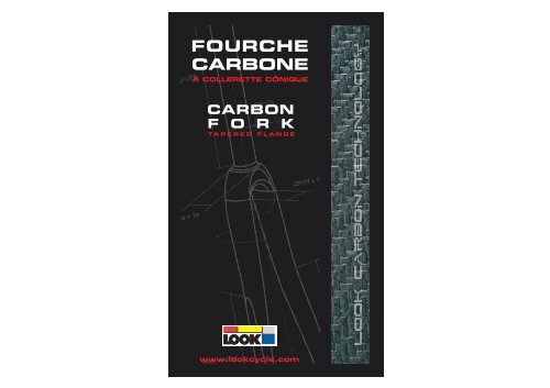
<strong>FOURCHE</strong><br />
<strong>CARBONE</strong><br />
A COLLERETTE CÔNIQUE<br />
CARBON<br />
F O R K<br />
TAPERED FLANGE<br />
www.lookcycle.com
4 - 7<br />
NOTICE DE MONTAGE - FRANCAIS<br />
Réf. : C0260 140<br />
<strong>FOURCHE</strong>S <strong>CARBONE</strong> A COLLERETTE CONIQUE A 36°<br />
8 - 11<br />
12 - 15<br />
MOUNTING INSTRUCTIONS - ENGLISH<br />
36° TAPERED FLANGE CARBON FORKS<br />
ISTRUZIONI DI MONTAGGIO - ITALIANA<br />
FORCELLE CARBONIO CON COLLARE CONICO A 36°<br />
16 - 19<br />
INSTRUCCIONES DE MONTAJE - ESPAGNOL<br />
HORQUILLAS DE CARBONO CON COLLARÍN CÓNICO DE 36°<br />
20 - 23<br />
BENUTZUNGSHINWEISE - DEUTSH<br />
CARBONGABELN MIT 36° KONUSAUFLAGE
FRANCAIS<br />
1<br />
<strong>FOURCHE</strong>S <strong>CARBONE</strong> A COLLERETTE CONIQUE A 36°<br />
Avant toute utilisation, lisez soigneusement l’intégralité de ces instructions,<br />
respectez les conseils donnés afin de garantir une bonne utilisation du produit.<br />
LOOK se réserve la possibilité de changer les spécifications du produit<br />
à sa guise et sans avis préalable dans le but de l’améliorer.<br />
PRESENTATION DU PRODUIT ET DE SES COMPOSANTS<br />
1”1/8 ème<br />
Cône à<br />
pente 36°<br />
Sachet<br />
KIT DE COMPRESSION<br />
Cet élément généralement<br />
livré avec<br />
le jeu de direction,<br />
n’est pas utilisé<br />
pour le montage<br />
des fourches à<br />
collerette conique.<br />
Bouchon de<br />
compression<br />
Expandeur<br />
Félicitations, vous venez d’acquérir une fourche LOOK 100% carbone monobloc.<br />
Cette fourche est conçue pour recevoir un jeu de direction intégré 1”1/8ème de type<br />
Aheadset dont les caractéristiques sont : Diam ext des roulements 41mm - pente 36°<br />
int. 45° ext. L’emballage de votre fourche contient : (voir Fig. a)<br />
• 1 fourche à collerette conique 36°<br />
• 1 sachet KIT DE COMPRESSION et sa notice<br />
• 4 spacers carbone (2X 5mm et 2x 10mm)<br />
• 1 bague spécifique<br />
• 1 écrou de fixation de frein<br />
• 1 notice de montage où figure la garantie du produit<br />
• Un rapport-test de rigidité de votre fourche<br />
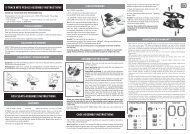
PROCESS DE MONTAGE DE LA <strong>FOURCHE</strong><br />
Fig. a<br />
4 5<br />
2<br />
NOTA : Il est fortement conseillé de s’adresser à un détaillant agréé LOOK pour effectuer<br />
un montage correct de votre fourche.<br />
La particularité d’une fourche carbone à collerette conique est que le roulement inférieur<br />
du jeu de direction est positionné directement sur la collerette moulée sans<br />
nécessiter de cuvette. (voir Fig.a )<br />
La fourche doit être posée sur une roue et une usure anormale des pattes qui serait<br />
due à une abrasion sur le sol ne peut être couverte par la garantie LOOK.<br />
Attention ! : Les fourches sont livrées avec un pivot d’une longueur de 300mm<br />
qu’il faut couper en fonction de la hauteur de la douille de direction du cadre.<br />
L’opération de coupe étant irréversible, nous vous conseillons de monter votre<br />
fourche avec des bagues d’épaisseur en dessous et au dessus de la potence.<br />
De cette manière vous pouvez baisser ou monter la potence en empilant les<br />
bagues au dessus ou en dessous de la potence. Lorsque vous êtes certain du<br />
réglage de la hauteur de la potence (après plusieurs sorties) et si vous décidez<br />
de ne plus changer de réglage, vous pourrez recouper la hauteur du pivot au plus<br />
juste en supprimant les bagues inutiles au dessus de la potence.<br />
Important : nous vous conseillons de toujours monter la bague spécifique de 5 mm<br />
(fournie avec votre fourche) au dessus de la potence afin que le serrage de celle-ci sur<br />
le pivot carbone de la fourche ne créé pas d’amorce de fissure. En éloignant le sommet<br />
du pivot de serrage supérieur de la potence, les risques de fissure du pivot sont<br />
considérablement réduits, surtout dans le cas d’un dépassement du couple de serrage<br />
préconisé.<br />
Le tube pivot carbone nécessite l’utilisation d'une potence appropriée. Les<br />
potences utilisées ne doivent pas présenter d'arrête vive aux bords de la surface<br />
de serrage. La présence de congé ou de chanfrein est indispensable pour une<br />
bonne utilisation de la fourche.<br />
• Faites le montage “à blanc” de l’ensemble des éléments de la fourche suivant la<br />
Fig.b sans serrer pour déterminer la longueur du tube pivot.<br />
1 - Installez le roulement inférieur sur la collerette cônique de la fouche en prenant soin<br />
de placer le chanfrein intérieur sur le cône.<br />
2 - Inserrez le tube pivot dans la douille de direction.<br />
3 - Placez le roulement supérieur dans la douille en plaçant le chanfrein extérieur vers le bas.<br />
4 - Montez la bague fendue sur le roulement, le cône vers le bas.<br />
5 - Inserrez les entretoises d’épaisseur si le capuchon touche la douille de direction.<br />
6 - Installez le capuchon à la suite de la bague fendue.<br />
7 - Disposez si nécessaire la ou les bagues d’épaisseur en fonction de la hauteur de<br />
potence désirée.<br />
8 - Procédez au montage de la potence sans bloquer les vis.<br />
9 - Maintenez fermement la fourche et appuyez sur la potence afin de compresser l’en<br />
semble de la direction.
10 - Ajoutez les bagues nécessaires et marquez le tube pivot.<br />
11 - Démontez tout pour couper le pivot de la fourche, 1 à 2mm sous l’endroit repèré.<br />
Nous vous recommandons d’utiliser un coupe tube ou une scie à métaux. (voir Fig.c )<br />
Bouchon de compression<br />
Expandeur<br />
bague spécifique<br />
Potence (8)<br />
Spacer (bague d’épaisseur) (7)<br />
Capuchon (6)<br />
Entretoises d’épaisseur (5)<br />
Bague fendue cônique (4)<br />
Roulement supérieur Ø41 (3)<br />
Douille de direction<br />
du cadre (2)<br />
Roulement inférieur Ø41 (1)<br />
Collerette cônique 36°<br />
de la fourche<br />
Fourche<br />
Fig. b<br />
Bouchon de<br />
compression<br />
Bague<br />
spécifique<br />
Potence<br />
Bague spécifique<br />
Potence<br />
Spacers<br />
(bagues d’épaisseur)<br />
Capuchon<br />
Douille de direction<br />
du cadre<br />
Fourche<br />
ATTENTION : Le carbone est un matériau trés abrasif qui détériore rapidement les<br />
outils. Si le tube pivot est trop long, la compression du jeu de direction sera insuffisante.<br />
Il s’en suivra une détérioration rapide du jeu de direction. Si le tube est trop<br />
court, la surface de contact entre le tube pivot et la potence sera trop faible et la tenue<br />
de la potence ne sera pas optimale. N’utilisez jamais de tube pivot fileté avec un jeu de<br />
direction pivot.<br />
• Remontez l’ensemble suivant le schema de montage de la Fig.b<br />
• Visser de quelques tours le bouchon de compression sur l’expandeur<br />
• Inserrez le kit de compression dans le tube pivot de la fourche.<br />
• Serrez la vis BTR5 de l’expandeur en passant par le trou de la vis du bouchon de<br />
compression, à l’aide d’une clef ALLEN n°6 (voir “Notice kit de compression”) afin de<br />
tasser le jeu de direction jusqu’à ce qu’aucun jeu ne soit perceptible dans la direction.<br />
*Pour “sentir” le jeu , serrez le frein avant et faites aller doucement la roue avant<br />
d’avant en arrière. Vous sentirez aisément le jeu au travers de votre main positionnée<br />
sur le cintre et qui serre le frein avant.<br />
*Attention si le capuchon du kit de compression touche le tube pivot le jeu est inréglable.<br />
Il faut toujours laisser 1 à 2mm entre le sommet de la dernière bague et le tube<br />
pivot de la fourche pour permettre au capuchon de jouer son rôle de compression du<br />
jeu de direction. (voir Fig.d )<br />
ATTENTION : Utilisez le bouchon fourni avec la fourche. Un bouchon mal adapté peut<br />
détériorer le pivot de fourche et provoquer un grave accident.<br />
• Resserrer les vis de la potence au couple maxi de 10 Nm.<br />
Fig. c<br />
1-2mm<br />
Fig. d<br />
IMPORTANT : Ne pas graisser le tube pivot. Ne pas serrer la potence sans le bouchon<br />
d’ajustement monté. Utilisez le kit de compression LOOK fourni avec la fourche ou un<br />
autre kit adapté à un pivot carbone car l’intérieur du kit de compression à une fonction<br />
: il sert a renforcer l'intérieur du pivot afin que celui-ci résiste à l’écrasement. N’utilisez<br />
que des potences ayant une surface de serrage supérieure à 1cm2. Proscrire tous les<br />
serrages par vis pointeau ainsi que tous les systèmes à griffes.<br />
3<br />
ENTRETIEN DE LA <strong>FOURCHE</strong><br />
Utiliser un chiffon doux et un détergent léger avec un peu d’eau pour nettoyer votre<br />
fourche, la sécher complètement après lavage ou utilisation dans des conditions climatiques<br />
humides. ATTENTION : ne pas utiliser de produits abrasifs, de solvants ou de<br />
jet d’eau à haute pression pour nettoyer votre fourche, cela annulerait la garantie<br />
LOOK.<br />
4<br />
GARANTIE<br />
Nos fourches sont garanties 5 ans à partir de la date d’achat contre tout vice ou défaut<br />
de fabrication. La peinture, les transferts, le vernis et tout ce qui concerne la finition<br />
sont garantis 1 an.<br />
Pour que la garantie soit valable, le volet ci-joint doit impérativement être rempli par le<br />
revendeur et retourné affranchi à LOOK CYCLE INTERNATIONAL seul habilité à valider<br />
l’avis de garantie. Cette garantie n’est pas transférable à autrui et une preuve<br />
d’achat est requise (facture originale).<br />
La garantie concerne les fourches pour tous vices ou défauts de fabrication.<br />
La garantie s’applique uniquement si la fourche est assemblée conformément aux instructions<br />
ci-dessus.<br />
La garantie ne s’applique pas aux défectuosités dues au mauvais entretien ou à une<br />
mauvaise utilisation.<br />
De même, la garantie est caduque si le produit a subi une modification technique du<br />
fait de l’utilisateur ou s’il a été réparé, repeint hors d’un centre de réparation agréé<br />
LOOK.<br />
Toute modification du produit annule la garantie. (Supression des ergots de sécurité ou<br />
perçage du carbone).<br />
La garantie ne couvre pas les cas suivants :<br />
• Les défauts causés par négligence ou entretien insuffisant<br />
• Les accidents<br />
• Les dommages accessoires et indirects<br />
Les dépenses de montage, démontage, temps de main d’oeuvre, emballage et expédition<br />
du cadre ne sont pas couverts.<br />
Ne pas percer, peindre ou revernir.<br />
Ne pas laisser la fourche près d’une source de chaleur.<br />
ATTENTION : Inspectez toujours votre vélo avant de l’utiliser. Si les tubes de votre<br />
cadre LOOK ou votre fourche ont subi n’importe quel dommage, rapportez le vélo chez<br />
votre revendeur LOOK pour une inspection. Respectez le code de la route. Prenez<br />
garde aux hasards de la route. Portez toujours un casque.<br />
6 7
ENGLISH<br />
1<br />
36° TAPERED FLANGE CARBON FORKS<br />
Before any use, carefully read all these instructions. In order to guarantee<br />
good use of the product all instructions are to be adhered to. LOOK reserves<br />
the right to change product specifications, at will, and without prior notice,<br />
for product improvement purposes..<br />
PRESENTATION OF THE PRODUCT AND ITS COMPONENTS<br />
1”1/8 ème<br />
36° taper<br />
COMPRESSION KIT sachet<br />
This element is<br />
not used for the<br />
assembly of tapered<br />
flange forks.<br />
Compression<br />
cap<br />
Cap<br />
Congratulations, you have just acquired a LOOK 100% carbon one-piece fork. This<br />
fork is designed to accommodate a 1 1/8” integrated headset of the Aheadset type. The<br />
specifications of which are: External diameter of the bearing 41 mm – gradient 36° int,<br />
45° ext. Your fork’s packaging contains: (see Figure A)<br />
• 1 36° tapered flange fork<br />
• 1 COMPRESSION KIT sachet<br />
• 4 5mm carbon spacers (2 x 5 mm and 2 x 10 mm)<br />
• 1 specific ring<br />
• 1 brake fixing bolt<br />
• 1 set of assembly instructions including the product guarantee<br />
• A rigidity test report for your fork<br />
FORK ASSEMBLY PROCEDURE<br />
Fig. a<br />
8 9<br />
2<br />
Note : It is strongly advised that an approved LOOK dealer is contacted for the correct<br />
installation of your fork.<br />
The particularity of a tapered flange carbon fork is that the lower bearing of the headset<br />
is placed directly on the moulded flange without requiring a cup (see Fig. a).<br />
The fork is to be placed on a wheel, and any abnormal wear of the dropouts resulting<br />
from contact with the ground, will not be covered under LOOK guarantee.<br />
Warning !: The forks are delivered with a 300 mm long pivot which has to be cut in<br />
accordance with the height of the frame head tube. The cutting operation is permanent<br />
so we would advise you to assemble your fork with spacers above and below the handlebar<br />
stem. You will then be able to lower or raise the handlebars by stacking the spacers<br />
above or below the handlebar stem. When you are certain that the handlebar stem<br />
height is correct after several trials, you can reduce the height of the pivot more precisely,<br />
by removing unnecessary spacers above the handlebar stem.<br />
Important: We would advise you to always fit the specific 5 mm ring (supplied with your<br />
fork) above the handlebar stem so its tightening on the carbon steering tube of the fork<br />
does not create a crack. By distancing the top of the upper tightening pivot from the<br />
handlebar stem, risk of pivot cracking is significantly reduced in the event that recommended<br />
tightening torque is exceeded.<br />
The carbon steering tube requires the use of an appropriate handlebar.<br />
Handlebar stems must not have sharp edges on the sides of the tightening surface.<br />
The presence of a chamfer is essential for correct use of the fork.<br />
• Carry out a trial assembly using parts as per Fig.b, without tightening in order to ascertain<br />
the length of the steering tube.<br />
Note : It is strongly advised that an approved LOOK dealer installs the fork.<br />
The particularity of a tapered flange carbon fork is that the lower bearing of the headset is<br />
placed directly on the moulded flange without requiring a cup (see Fig. a). The fork is to be<br />
placed on a wheel, and any abnormal wear of the dropouts resulting from contact with the<br />
ground, will not be covered under LOOK warantee.<br />
1 - Install the lower bearing on the tapered flange of the fork taking care to fit the bot<br />
tom chamfer on the cone.<br />
2 - Insert the steering tube in the frame head tube.<br />
3 - Place the upper bearing on the head tube by placing the external chamfer towards<br />
the bottom.<br />
4 - Fit the split bushing on the bearing, the cone towards the bottom.<br />
5 - Install the spacers if the cap touches the head tube.<br />
6 - Install the cap after the split bushing.<br />
7 - If necessary, fit the spacer(s) depending upon the height of the handlebar stem required.<br />
8 - Assemble the handlebar stem without fully tightening the screws.<br />
9 - Firmly hold the fork and press on the handlebar stem in order compress the entire<br />
steering unit.<br />
10 - Add the necessary rings, and mark the steering tube.<br />
11 - Dismantle everything to cut the fork steering tube, 1 to 2 mm under the mark.<br />
We recommend that you use a tube cutter or metal saw. ( see Fig.c )
Compression cap<br />
Expander bolt<br />
Specific ring<br />
Spacer (7)<br />
Cap (6)<br />
Spacers (5)<br />
Split tapered bushing (4)<br />
Handlebar stem (8)<br />
Upper bearing diameter 41 (3)<br />
Frame head tube (2)<br />
Lower bearing diameter 41 (1)<br />
36° fork taper<br />
Fork<br />
Fig. b<br />
Compression<br />
cap<br />
Specific<br />
ring<br />
Handlebar<br />
stem<br />
Specific ring<br />
Spacers<br />
Cap<br />
Frame head tube<br />
Fork<br />
Handlebar stem<br />
Fig. c<br />
1-2mm<br />
Fig. d<br />
Warning: Carbon is a highly abrasive material which rapidly wears tools. If the steering<br />
tube is too long, compression of the headset will be insufficient, and it will deteriorate<br />
the headset very quickly. If the tube is too short the contact surface between<br />
the steering tube and the handlebar stem will too little and handlebar stem retention<br />
will not be at its maximum. Never use a threaded steering tube with a pivot headset.<br />
WARNING: Use the cap supplied with the fork. A poorly fitting cap can damage the<br />
pivot of the fork and cause a serious accident.<br />
• Re-assemble the entire unit as per the assembly diagram in Fig.b.<br />
• Screw, a few turns, the compression cap on the expander bolt.<br />
• Insert the compression kit in the steering tube of the fork.<br />
• Tighten the BTR5 screw of the expander by passing through the hole of the compression<br />
cap screw using a number 6 Allen key (see compression kit instructions) in order<br />
to push down the headset until no play is perceptible in the steering.<br />
* To “feel” the play, tighten the front brake and slightly turn the front wheel forwards and<br />
backwards. You will easily feel the play with your hand placed on the handlebar and<br />
which tightens the front brake.<br />
Warning: If the cap of the compression kit touches the steering tube, play can not be<br />
adjusted. 1 to 2 mm must always be left between the top of the last ring and the steering<br />
tube of the fork to enable the cap to play its role of headset compression (see Fig. d).<br />
WARNING: Use the cap supplied with the fork. A poorly adapted cap can damage the<br />
pivot of the fork and cause a serious accident.<br />
• Re-tighten the screws of the stem to a maximum torque of 10 Nm.<br />
Important: Do not grease the steering tube. Do not tighten the handlebar stem without<br />
the adjustment cap being installed. Use the LOOK compression kit supplied with the<br />
fork or another kit adapted for a carbon pivot, because the inside of the compression<br />
kit has a purpose: it serves to reinforce the inside of the pivot in order that this resists<br />
crushing. Only use handlebar stems having a tightening surface which is greater than<br />
1 cm2 . No tightening using cone-point set screw or gripping system are allowed.<br />
3<br />
FORK MAINTENANCE<br />
Use a soft cloth and a mild detergent with a little water to clean your fork, completely<br />
dry after washing, or if used in damp conditions.<br />
Warning: do not use any abrasive product, solvent, or high-pressure water to clean<br />
your fork, this will render the LOOK guarantee null and void.<br />
4<br />
LIMITED WARANTIE<br />
Our forks are waranted for five years as from the date of purchase. The paint, decals,<br />
and varnish are all, along with the finish, waranted for one year. In order that the warantee<br />
be valid, it is essential that attached form be completed by the retailer and returned<br />
stamped to LOOK <strong>Cycle</strong> International who, alone, is authorised to make warantee decisions.<br />
This warantee is not transferable to a third party and proof of purchase is required<br />
(original invoice).<br />
The warantee is not valid for defects arising out of poor maintenance, misuse or abuse.<br />
Furthermore, the warantee is null and void if the fork has been modified by the user or<br />
if it has been repaired, or re-painted in other than a <strong>Look</strong> approved centre.<br />
Any modification of the product cancels the warantee.(safety pin removal or drilling of<br />
the carbon).<br />
The following cases are not covered by the warantee:<br />
• damage cause by negligence or insufficient maintenance<br />
• accidents.<br />
• other direct or indirect damage.<br />
Assembly and disassembly expenses, labour, packaging and shipping of the frame are<br />
not covered.<br />
Do not drill holes, paint, or re-varnish.<br />
Do not leave the fork near a source of heat.<br />
Warning: Always inspect your bike before use. If the tube of your LOOK frame or your<br />
fork have been subject to any damage what so ever, return the bike to your<br />
LOOK retailer for inspection. Follow the rules of the road. Take care on the road.<br />
Always wear a helmet.<br />
Always inspect your bike before use. If the tube of your LOOK frame or your fork have<br />
been subject to any damage what so ever, return the bike to your LOOK retailer for inspection.<br />
Keep the highway code. Take care on the road. Always wear a helmet.<br />
10 11
ITALIANO<br />
FORCELLE CARBONIO CON COLLARE CONICO A 36°<br />
Prima di ogni utilizzo, leggere accuratamente tutte le presenti istruzioni ed<br />
attenersi ai consigli dati al fine di utilizzare il prodotto correttamente.<br />
LOOK si riserva la possibilità di cambiare le caratteristiche del prodotto a<br />
suo piacimento e senza alcun preavviso al fine di migliorarlo.<br />
1<br />
PRESENTAZIONE DEL PRODOTTO E DEI SUOI COMPONENTI<br />
1”1/8<br />
Cono con<br />
angolo 36°<br />
KIT DI COMPRESSIONE<br />
Questo elemento<br />
non viene utilizzato<br />
per il montaggio<br />
delle forcelle<br />
con collare conico<br />
Tappo di<br />
compressione<br />
Espansore<br />
Fig. a<br />
Congratulazioni! Lei ha appena acquistato una forcella LOOK monoscocca 100%<br />
carbonio.<br />
Questa forcella è stata progettata per ospitare una serie sterzo integrata 1”1/8 di tipo<br />
Aheadset le cui caratteristiche sono: diametro esterno dei cuscinetti 41 mm – angolo<br />
36° int. 45° est. L’imballaggio della vostra forcella contiene: (vedi Fig. a)<br />
• 1 Forcella a collare conico 36°<br />
• 1 KIT DI COMPRESSIONE<br />
• 4 distanziali in carbonio ( 2 x 5 mm e 2 x 10 mm)<br />
• 1 anello adattatore<br />
• 1 vite di fissaggio del freno<br />
• Istruzioni di montaggio e garanzia del prodotto<br />
• Un rapporto riguardante test di rigidità della forcella<br />
2<br />
NORME DI MONTAGGIO DELLA FORCELLA<br />
Nota: E’ vivamente consigliato di rivolgersi ad un rivenditore autorizzato LOOK per<br />
eseguire un montaggio corretto della vostra forcella.<br />
La particolarità di una forcella in carbonio a collare conico consiste nel fatto che il<br />
cuscinetto interno dello sterzo di direzione sia posizionato direttamente sul collare<br />
stampato senza l’ausilio di adattatori. (vedi Fig. a).<br />
La forcella deve essere montata ed un’usura anormala degli steli dovuta ad un’abrasione<br />
sul suolo non rientra nella garanzia LOOK.<br />
Attenzione! Le forcelle sono complete di pivot con lunghezza di 300 mm che<br />
occorre tagliare in funzione dell’altezza del tubo sterzo completo di serie sterzo.<br />
L’operazione di taglio è irreversibile. Vi consigliamo pertanto di montare la vostra<br />
forcella con anelli di spessore al di sotto ed al di sopra del pivot. In questo<br />
modo, potete abbassare o sollevare l’attacco manubrio disponendo gli anelli al<br />
di sopra o al di sotto dello stesso. Quando siete certi della misura dell’altezza,<br />
potete tagliare in modo esatto la lunghezza del pivot eliminando gli anelli inutili<br />
al di sopra dell’attacco manubrio.<br />
Importante: vi consigliamo di montare sempre l’anello specifico di 5 mm (fornito con la<br />
vostra forcella) al di sopra dell’attacco manubrio in modo tale che la chiusura di<br />
quest’ultimo avvenga interamente sul pivot in carbonio della forcella e non crei alcuna<br />
possibilità di danneggiamento, soprattutto in caso di superamento dei parametri di<br />
chiusura raccomandati.<br />
Il pivot in carbonio richiede l’utilizzo di un apposito attaco manubrio. I che non<br />
deveno presentare spigoli vivi sui bordi della superficie di serraggio. La presenza<br />
di goli o smuss è indispensabile per un corretto utilizzo della forcella.<br />
• Eseguite il montaggio di prova (non definitivo) dell’insieme degli elementi come<br />
dalla Fig. b senza serrare al fine di determinare la lunghezza del tubo perno.<br />
1 - Installate il cuscinetto inferiore sul collare conico della forcella facendo attenzione<br />
a posizionare lo smusso interno sul cono.<br />
2 - Inserite il pivot nel tubo sterzo del telaio.<br />
3 - Posizionate il cuscinetto superiore nelturo sterzo posizionando lo smusso esterno<br />
in basso.<br />
4 - Montate l’anello spaccato sul cuscinetto, il cono rivolto in basso.<br />
5 - Inserite gli spessori nel caso la calotta superiore interferisca con il tubo sterzo.<br />
6 - installate la calotta dopo l’anello spaccato.<br />
7 - Disponete, se necessario, il/gli anelli di spessore in funzione dell’altezza dell’attacco<br />
manubrio.<br />
8 - Procedete al montaggio dell’attacco manubrio senza bloccare le viti.<br />
9 - Mantenete bloccata la forcella e premete l’attacco manubrio al fine di compattare la<br />
12 13
serie sterzo.<br />
10 - Aggiungete gli anelli necessari e contrassegnate il tubo pivot.<br />
11 - Smontate il tutto per tagliare il pivot della forcella 2 mm sotto il riferimento.<br />
Vi consigliamo di utilizzare un taglia tubi o un sega per metalli. (vedi Fig. c)<br />
Tappo di compressione<br />
Espansore<br />
Anello specifico<br />
Attaco<br />
manubrio (8)<br />
Spessore (7)<br />
Cappuccio (6)<br />
Distanziali (5)<br />
Anello spaccato conico (4)<br />
Cuscinetto superiore Δ41 (3)<br />
Tubo sterzo (2)<br />
Cuscinetto inferiore Δ41 (1)<br />
Collare conico 36° della forcella<br />
Forcella<br />
Fig. b<br />
Tappo di<br />
compressione<br />
Anello<br />
adattatore<br />
Tubo<br />
Sterzo<br />
Anello adattatore<br />
Attacco manubrio<br />
Spessore<br />
Cappuccio<br />
Tubo sterzo<br />
Forcella<br />
Attenzione. Il carbonio è un materiale molto abrasivo e deteriora molto rapidamente gli<br />
utensili. Qualora il pivot fosse troppo lungo, la compressione della serie sterzo sarà<br />
insufficiente. Ciò provocherà un deterioramento rapido dello stesso. Qualora il tubo<br />
fosse troppo corto, la superficie di contatto sarà insufficiente e la tenuta dell’attacco<br />
manubrio non sarà ottimale. Non utilizzare mai un pivot filettato con una serie sterzo<br />
integrata.<br />
• Rimontate l’insieme secondo lo schema di montaggio della Fig. b.<br />
• Avvitate di alcuni giri il tappo di compressione dell’espansore.<br />
• Inserite il kit di compressione pivot della forcella.<br />
• Serrate la vite BTRS dell’espansore, per mezzo di una chiave ALLEN n.6 (vedi<br />
istruzioni “kit di compressione) finché alcun movimento sia percettibile nello sterzo.<br />
• Al fine di “percepire” il gioco, serrate il freno anteriore e fate andare delicatamente<br />
la ruota anteriore avanti-indietro. Sentirete facilmente la portata del gioco attraverso<br />
la vostra mano posizionata tra il tubo sterzo e la testa della forcella.<br />
* Attenzione. Qualora il tappo del kit di compressione dovesse toccare il pivot, il gioco<br />
non potrebbe essere regolato. Occorre sempre lasciare 1 - 2 mm tra la sommità<br />
dell'ultimo anello ed il pivot perno della forcella per permettere al tappo di svolgere il<br />
proprio ruolo di compressione dello sterzo (vedi Fig. d).<br />
Attenzione: Utilizzate il tappo fornito con la forcella. Un tappo inadatto potrebbe<br />
deteriorare la forcella e provocare gravi incidenti.<br />
• Bloccate le viti dell’attaco manubrio con una coppia max. di 10 Nm.<br />
Fig. c<br />
1-2mm<br />
Fig. d<br />
IMPORTANTE: Non lubrificare il pivot. Non bloccare definivamente l’attaco<br />
manubrio senza che il tappo di compressione sia montato. Utilizzare il kit di compressione<br />
LOOK fornito con la forcella o un altro kit adatto ad un perno in carbonio<br />
poiché l’apposito expander serve a rinforzare l’interno del pivot in modo tale<br />
che quest’ultimo resista allo schiacciamento. Utilizzate soltanto attachi manubrio<br />
aventi una superficie di chiusura superiore a cm2. Non usare sistemi di fissaggio<br />
con viti autofilettanti o sistemi a ganascia.<br />
3<br />
MANUTENZIONE DELLA FORCELLA<br />
Utilizzate un panno morbido ed un detergente delicato con un po’ di acqua per pulire<br />
la vostra forcella; asciugatela interamente dopo il lavaggio o utilizzo in condizioni climatiche<br />
umide. ATTENZIONE: non utilizzare prodotti abrasivi, solventi o getti d’acqua<br />
ad alta pressione per pulire la vostra forcella. Ciò annullerebbe la garanzia.<br />
4<br />
GARANZIA<br />
Le nostre forcelle sono garantite 5 anni a partire dalla data d’acquisto, contro qualsiasi<br />
vizio o difetto di produzione. La verniciatura, i transfer, la lacca e tutto ciò che<br />
concerne la finitura sono garantiti 1 anno.<br />
Per far sì che la garanzia sia valida, il modulo allegato deve essere tassativamente<br />
compilato dal rivenditore e rinviato affrancato a LOOK CYCLE INTERNAZIONALE,<br />
unico centro autorizzato a convalidare la garanzia. La presente garanzia non è trasferibile<br />
a terzi ed è richiesta un prova di acquisto (fattura originale).<br />
La garanzia riguarda le forcelle per tutti i vizi o difetti di fabbricazione.<br />
La garanzia si applica soltanto se la forcella è stata assemblata conformemente alle<br />
istruzioni di cui sopra.<br />
La garanzia non si applica ai difetti dovuti all’errata manutenzione o all’errato utilizzo<br />
della forcella.<br />
Analogamente, la garanzia è nulla se la forcella ha subito una modifica da parte dell'utilizzatore<br />
o se non è stata riparata, riverniciata da un centro di riparazione autorizzato<br />
LOOK.<br />
Qualsiasi modifica del prodotto annulla la garanzia. (Eliminazione dei nottolini di sicurezza<br />
o foratura del carbonio).<br />
La garanzia non copre i seguenti casi:<br />
• I difetti dovuti a negligenza o manutenzione insufficiente<br />
• Gli incidenti<br />
• I danni accessori ed indiretti<br />
Le spese di montaggio, smontaggio, tempo di manodopera, imballaggio e spedizione<br />
del telaio non sono coperte.<br />
Non forare, verniciare o rilaccare.<br />
Non lasciare la forcella vicino ad una sorgente di calore.<br />
ATTENZIONE: Ispezionate sempre la vostra bicicletta prima di utilizzarla. Se i tubi<br />
del vostro telaio LOOK o la vostra forcella hanno subito un danno, restituite la bicicletta<br />
al vostro rivenditore LOOK per un’ispezione della stessa. Rispettate il codice<br />
della strada. Fate attenzione agli imprevisti. Indossate sempre un casco.<br />
14 15
ESPAÑOL<br />
HORQUILLAS DE CARBONO CON COLLARÍN CÓNICO DE 36°<br />
Antes de cualquier utilización, lea atentamente la totalidad de estas instrucciones,<br />
respete los consejos dados con el fin de garantizar una buena utilización<br />
del producto. LOOK se reserva la posibilidad de cambiar las especificaciones<br />
del producto a su criterio y sin aviso previo con el objetivo de<br />
mejorarlo.<br />
1<br />
PRESENTACIÓN DEL PRODUCTO Y DE SUS COMPONENTES<br />
1”1/8°<br />
Cono de<br />
pendiente 36°<br />
Bolsita<br />
KIT DE COMPRESSION<br />
Este elemento no<br />
se utiliza para el<br />
montaje de las<br />
horquillas de collarín<br />
cónico.<br />
Tapón de<br />
compresión<br />
Extensor<br />
Felicidades, acaba de adquirir una horquilla LOOK 100% carbono monobloque. Esta<br />
horquilla está diseñada para recibir un juego de dirección integrado 1”1/8º de tipo<br />
Aheadset cuyas características son: Diám. ext. de los rodamientos 41mm - pendiente<br />
36° int. 45° ext. El embalaje de su horquilla contiene: (ver Fig. a)<br />
• 1 Horquilla de collarín cónico 36°<br />
• 1 Bolsita KIT DE COMPRESSION<br />
• 4 spacers carbono de 5mm (2X 5mm y 2x 10mm)<br />
• 1 anillo específico<br />
• tuerca de fijacion de freno<br />
• 1 Instrucciones de montaje en donde figura la garantía del producto<br />
• Un informe-test de rigidez de la horquilla<br />
2<br />
PROCESO DE MONTAJE DE LA HORQUILLA<br />
NOTA: Se aconseja encarecidamente dirigirse a un detallista autorizado LOOK para<br />
efectuar un montaje correcto de la horquilla.<br />
La particularidad de una horquilla de carbono de collarín cónico es que el rodamiento<br />
inferior del juego de dirección se posiciona directamente sobre el collarín<br />
moldeado sin necesidad de cubeta. (ver Fig. a)<br />
La horquilla tiene que colocarse sobre una rueda. Un desgaste anormal de las patas<br />
que se deba a una abrasión en el suelo no puede ser cubierto por la garantía LOOK.<br />
¡Atención! : Las horquillas se entregan con un pivote de una longitud de 300 mm<br />
que hay que cortar en función de la altura del casquillo de dirección del bastidor.<br />
Al ser la operación de corte irreversible, le aconsejamos montar su horquilla<br />
con anillos de espesor por debajo y por encima del montante. De esta manera<br />
puede bajar o subir el montante apilando los anillos por encima o por debajo del<br />
montante. Cuando esté seguro del ajuste de la altura del montante (después de<br />
varias pruebas) y si decide no cambiar de ajuste, podrá recortar la altura del<br />
pivote de manera más justa suprimiendo los anillos inútiles encima del montante.<br />
Importante: le aconsejamos montar siempre el anillo específico de 5 mm (suministrado<br />
con la horquilla) por encima del montante para que el apriete de éste en el pivote de<br />
carbono de la horquilla no produzca ningún principio de fisura. Alejando el vértice del<br />
pivote de apriete superior del montante, los riesgos de fisura del pivote quedan considerablemente<br />
reducidos, sobre todo en el caso de un rebasamiento del par de apriete<br />
recomendado.<br />
El tubo pivote de carbono necesita una utilización de un montante apropiado.<br />
Los montantes utilizados no deben presentar ninguna arista viva en los bordes<br />
de la superficie de apriete. La presencia de redondeo o de achaflanado es<br />
indispensable para una buena utilización de la horquilla.<br />
• Haga el montaje “en blanco” del conjunto de los elementos según la Fig.b sin apretar<br />
para determinar la longitud del tubo pivote.<br />
1 - Instale el rodamiento inferior en el collarín cónico de la horquilla teniendo cuidado<br />
de colocar el chaflán interior sobre el cono.<br />
2 - Inserte el tubo pivote en el casquillo de dirección.<br />
3 - Coloque el rodamiento superior en el casquillo situando el chaflán exterior hacia<br />
abajo.<br />
4 - Monte el anillo hendido en el rodamiento, el cono hacia abajo.<br />
5 - Inserte las riostras de espesor si el capuchón toca el casquillo de dirección.<br />
6 - Instale el capuchón inmediatamente después del anillo hendido.<br />
7 - Coloque si es necesario el o los anillos de espesor en función de la altura del mon<br />
tante deseado.<br />
8 - Proceda al montaje del montante sin bloquear los tornillos.<br />
Fig. a<br />
9 - Sujete la horquilla y apoye en el montante con el fin de comprimir el conjunto de la<br />
16 17
dirección.<br />
10 - Añada los anillos necesarios y marque el tubo pivote.<br />
11 - Desmonte todo para cortar el pivote de la horquilla, 1 a 2mm debajo del lugar refe<br />
renciado. Le recomendamos utilizar un corta tubo o una sierra de metales.<br />
(ver Fig. c)<br />
Tapón de compresión<br />
Extensor<br />
Anillo específico<br />
Montante (8)<br />
Spacer (anillo de espesor) (7)<br />
Capuchón (6)<br />
Riostras de espesor (5)<br />
Anillo hendido cónico (4)<br />
Rodamiento superior Ø41 (3)<br />
Direccion del cuadro (2)<br />
Rodamiento inferior Ø41 (1)<br />
Collarín cónico 36° de la horquilla<br />
Horquilla<br />
Fig. b<br />
Tapón de<br />
compresión<br />
Anillo<br />
específico<br />
Montante<br />
Anillo específico<br />
Montante<br />
Spacers<br />
(anillo de esperor)<br />
Capuchón<br />
Casquillo de dirección<br />
del bastidor<br />
Horquilla<br />
Fig. c<br />
1-2mm<br />
Fig. d<br />
ATENCIÓN: El carbono es un material muy abrasivo que deteriora rápidamente las herramientas.<br />
Si el tubo pivote es demasiado largo, la compresión del juego de dirección<br />
será insuficiente. El resultado será un deterioro rápido del juego de dirección. Si el<br />
tubo es demasiado corto, la superficie de contacto entre el tubo pivote y el montante<br />
será demasiado débil y el aguante del montante no será óptimo. No utilice nunca un<br />
tubo pivote fileteado con un juego de dirección pivote.<br />
• Vuelva a montar el conjunto según el esquema de montaje de la Fig. b<br />
• Atornille algunas vueltas el tapón de compresión sobre el extensor<br />
• Inserte el kit de compresión en el tubo pivote de la horquilla.<br />
• Apriete el tornillo BTR5 del extensor pasando por el agujero del tornillo del tapón de<br />
compresión, con ayuda de una llave ALLEN n°6 (ver “Instrucciones kit de compresión”)<br />
con el fin de asentar el juego de dirección hasta que no sea perceptible ningún juego<br />
en la dirección.<br />
*Para “notar” el juego, apriete el freno delantero y accione suavemente la rueda delantera,<br />
de delante hacia atrás. Notará fácilmente el juego en su mano posicionada sobre<br />
el manillar y apretando el freno delantero.<br />
*Atención si el capuchón del kit de compresión toca el tubo pivote, el juego no se<br />
puede ajustar. Hay que dejar siempre 1 a 2 mm entre el vértice del último anillo y el<br />
tubo pivote de la horquilla para permitir al capuchón jugar su papel de compresión del<br />
juego de dirección. (ver Fig. d)<br />
ATENCIÓN: Utilice el tapón suministrado con la horquilla. Un tapón mal adaptado<br />
puede deteriorar el pivote de horquilla y provocar un grave accidente.<br />
IMPORTANTE: No engrasar el tubo pivote. No apretar el montante sin el tapón<br />
de ajuste montado. Utilice el kit de compresión LOOK suministrado con la horquilla<br />
u otro kit adaptado a un pivote carbono pues el interior del kit de compresión<br />
tiene una función: sirve para reforzar el interior del pivote para que<br />
éste resista al aplastamiento. Utilice solamente montantes con una superficie<br />
de apriete superior a 1cm2. Evitar absolutamente todos los aprietes efectuados<br />
con tornillo punzón así como todos los sistemas de grapas.<br />
MANTENIMIENTO DE LA HORQUILLA<br />
• Volver a apretar los tornillos del montante al par máx. de 10 Nm.<br />
18 19<br />
3<br />
Utilizar un trapo suave y un detergente ligero con un poco de agua para limpiar la<br />
horquilla, secarla completamente después del lavado o de su utilización en condiciones<br />
climáticas húmedas. ATENCIÓN: no utilizar productos abrasivos, disolventes o<br />
chorro de agua de alta presión para limpiar la horquilla, esto anularía la garantía<br />
LOOK.<br />
4<br />
GARANTÍA<br />
Nuestras horquillas están garantizadas durante 5 años a partir de la fecha de compra<br />
contra cualquier vicio o defecto de fabricación. La pintura, las transferencias, el<br />
barniz y todo lo relativo al acabado están garantizados durante 1año.<br />
Para que la garantía sea válida, la hoja adjunta debe imprescindiblemente ser rellenada<br />
por el vendedor y devuelta debidamente franqueada a LOOK CYCLE INTER-<br />
NATIONAL, el único habilitado para validar el aviso de garantía. Esta garantía no es<br />
transferible a ningún otro y se requiera la correspondiente prueba de compra (factura<br />
original).<br />
La garantía se refiere a las horquillas para cualesquiera vicios o defectos de fabricación.<br />
La garantía se aplica únicamente si la horquilla se monta conforme a las instrucciones<br />
más arriba.<br />
La garantía no se aplica a los defectos debidos a un mantenimiento incorrecto o a<br />
una mala utilización.<br />
Asimismo, la garantía caduca si ha sufrido una modificación técnica por el usuario o<br />
si el producto ha sido reparado o repintado fuera de un centro de reparación autorizado<br />
LOOK.<br />
Cualquier modificación del producto anula la garantía. (Supresión de los espárragos<br />
de seguridad o taladrado del carbono).<br />
La garantía no cubre los casos siguientes:<br />
• Los defectos causados por negligencia o mantenimiento insuficiente<br />
• Los accidentes<br />
• Los daños accesorios e indirectos<br />
Los gastos de montaje, desmontaje, tiempo de mano de obra, embalaje y expedición<br />
del bastidor no están cubiertos.<br />
No agujerear, pintar o volver a barnizar.<br />
No dejar la horquilla cerca de una fuente de calor.<br />
ATENCIÓN: Inspeccione siempre su bicicleta antes de utilizarla. Si los tubos del bastidor<br />
LOOK o la horquilla han sufrido algún daño, lleve la bicicleta a su vendedor<br />
LOOK para una inspección. Respete el código de la circulación. Esté atente a los<br />
avatares de la carretera. Lleve siempre un casco.
DEUTSCH<br />
1<br />
CARBONGABELN MIT 36° KONUSAUFLAGE<br />
Lesen Sie bitte vor der Benutzung sorgfältig alle Anweisungen durch und<br />
beachten Sie die angeführten Warnhinweise, um den sachgemäßen<br />
Gebrauch des Produkts zu gewährleisten. LOOK behält sich das Recht vor,<br />
die Produktspezifikationen nach ihrem Erachten und ohne vorherige<br />
Ankündigung zu deren Verbesserung zu verändern.<br />
BESCHREIBUNG DES PRODUKTS UND SEINER BAUTEILE<br />
1 1/8”<br />
36°<br />
Konus<br />
KLEMMSATZ Beutel<br />
Bei derMontage<br />
von Gabeln mit<br />
Konusauflage wird<br />
dieses Teil nicht<br />
verwendet.<br />
Klemmstopfen<br />
Expander<br />
Wir gratulieren Ihnen zum Erwerb einer LOOK Monobloc Vollcarbon-Gabel.<br />
Diese Gabel wurde speziell für einen integrierten 1 1/8" Steuersatz vom Typ<br />
Aheadset mit den folgenden Merkmalen entwickelt: Lageraußendurchmesser 41 mm<br />
– Schräge 36° innen, 45° außen. Ihr Gabelset enthält (siehe Abb. a):<br />
• 1 Gabel mit 36° Konusauflage<br />
• 1 KLEMMSATZ-Beutel<br />
• 4 Carbonspacers 5 mm (je 2 x 5 mm und 2 x 10 mm)<br />
• 1 spezifischer Ring<br />
• 1 Bremsbefestigungsmutte<br />
• 1 Montageanleitung mit der Produktgarantie<br />
• Testbericht zur Verwindungssteifigkeit Ihrer Gabel<br />
2<br />
GABELMONTAGE<br />
ANMERKUNG: Um die korrekte Montage Ihrer Gabel zu gewährleisten, empfehlen wir<br />
Ihnen, sich an einen LOOK Vertragshändler zu wenden.<br />
Die Besonderheit einer Carbongabel mit Konusauflage besteht darin, dass das untere<br />
Lager des Steuersatzes unmittelbar auf der geformten Auflage positioniert wird, ohne<br />
dass dazu eine Lagerschale erforderlich ist (siehe Abb. a).<br />
Die Gabel muss auf ein Rad aufgesetzt werden; die LOOK Garantie gilt nicht für einen<br />
anormalen Verschleiß der Ausfallenden, der auf ein Reiben auf dem Boden zurückzuführen<br />
ist.<br />
Achtung: Die Gabeln werden mit einem 300 mm langen Gabelschaftrohr geliefert,<br />
das je nach der Höhe des Gabelschafts des Rahmens abzusägen ist. Das<br />
Absägen kann nicht rückgängig gemacht werden. Deshalb raten wir Ihnen, Ihre<br />
Gabel unter und über dem Lenkervorbau mit Distanzringen zu montieren. Auf<br />
diese Weise können Sie den Lenkervorbau nach unten oder oben verschieben,<br />
indem Sie die Distanzringe über oder unter dem Vorbau zusammenschieben.<br />
Wenn Sie sicher sind, die richtige Höheneinstellung des Lenkervorbaus gefunden<br />
zu haben (nach mehreren Probefahrten), und die Einstellung nicht mehr<br />
verändern wollen, können Sie die überflüssigen Distanzringe über dem<br />
Lenkervorbau entfernen und das Gabelschaftrohr auf die genaue Höhe absägen.<br />
Wichtig: Wir raten Ihnen, auf jeden Fall den spezifischen 5 mm Ring (mit Ihrer Gabel<br />
geliefert) über dem Lenkervorbau zu montieren, damit dessen Klemmung auf dem<br />
Carbon-Gabelschaftrohr keinen Rissbeginn verursachen kann. Das Wegrücken des<br />
Scheitelpunkts des oberen Klemmrohrs vom Lenkervorbau mindert die Rissgefahr<br />
des Gabelschaftrohrs beträchtlich, insbesondere falls das empfohlene<br />
Anzugsmoment überschritten wird.<br />
Das Carbon-Gabelschaftrohr erfordert die Verwendung eines passenden<br />
Lenkervorbaus. Die verwendeten Lenkervorbauten dürfen keinesfalls scharfe<br />
Kanten an den Rändern der Klemmfläche aufweisen. Für einen sachgemäßen<br />
Gebrauch der Gabel ist eine Abrundung oder Anfasung unerlässlich<br />
• Montieren Sie "zur Probe" sämtliche Bauteile gemäß Abb. b ohne Klemmung, um<br />
die Länge des Gabelschaftrohrs zu bestimmen.<br />
1 - Das untere Lager auf die Konusauflage der Gabel setzen und dabei darauf achten,<br />
dass die innere Anfasung auf dem Konus aufliegt.<br />
2 - Das Gabelschaftrohr in den Gabelschaft einführen.<br />
3 - Das obere Lager mit der äußeren Anfasung nach unten in den Gabelschaft einset<br />
zen.<br />
4 - Den konischen Schlitzring mit dem Konus nach unten auf das Lager setzen.<br />
5 - Distanzstücke verwenden, falls die Abdeckkappe den Gabelschaft berührt.<br />
6 - Die Abdeckkappe auf den Schlitzring setzen.<br />
Fig. a<br />
7 - Je nach gewünschter Vorbauhöhe erforderlichenfalls einen oder mehrere<br />
20 21
Distanzringe verwenden.<br />
8 - Den Lenkervorbau montieren, ohne die Schrauben anzuziehen.<br />
9 - Die Gabel gut festhalten und auf den Lenkervorbau drücken, um die gesamte<br />
Lenkung zu klemmen.<br />
10 - Die erforderlichen Ringe hinzufügen und das Gabelschaftrohr markieren.<br />
11 - Alles auseinandernehmen und das Gabelschaftrohr 1 bis 2 mm unter der<br />
Markierung absägen. Wir empfehlen Ihnen, dazu einen Rohrschneider oder eine<br />
Metallsäge zu verwenden (siehe Abb. c).<br />
Klemmstopfen<br />
Expander<br />
Spezifischer Ring<br />
Spacer (Distanzring) (7)<br />
Abdeckkappe (6)<br />
Distanzstücke (5)<br />
Konischer Schlitzring (4)<br />
Oberes Lager Ø 41 (3)<br />
Lenkervorbau (8)<br />
Steuerrohr des Rahmens (2)<br />
Unteres Lager Ø 41 (1)<br />
36° Konusauflage der Gabel<br />
Gabel<br />
Fig. b<br />
Klemmstopfen<br />
Spezifischer<br />
Ring<br />
Lenkervorbau<br />
Spezifischer Ring<br />
Lenkervorbau<br />
Spacers (Distanzringe)<br />
Abdeckkappe<br />
Steuerrohr des Rahmens<br />
Gabel<br />
Fig. c<br />
1-2mm<br />
Fig. d<br />
ACHTUNG: Carbon ist ein stark reibendes Material, das Werkzeuge schnell abnutzt.<br />
Wenn das Gabelschaftrohr zu lang ist, ist die Klemmung des Steuersatzes ungenügend.<br />
Dies zieht eine rasche Beschädigung des Steuersatzes nach sich. Ist das<br />
Gabelschaftrohr zu kurz, ist die Kontaktfläche zwischen dem Gabelschaftrohr und dem<br />
Lenkervorbau zu gering und der Vorbau hat keinen optimalen Halt. Verwenden Sie auf<br />
keinen Fall ein Gabelschaftrohr mit Gewinde zusammen mit einem gewindelosen<br />
Steuersatz.<br />
• Die Lenkung gemäß dem Montageschema in Abb. b wieder zusammenbauen.<br />
• Den Klemmstopfen mit mehreren Umdrehungen auf den Expander schrauben.<br />
• Den Klemmsatz in das Gabelschaftrohr einsetzen.<br />
• Die BTR5 Schraube des Expanders durch das Loch der Schraube des<br />
Klemmstopfens führen und mit Hilfe eines 6er Sechskantsteckschlüssels (siehe<br />
Anleitung für Klemmsatz) festziehen, dabei den Steuersatz solange zusammenzudrücken,<br />
bis in der Lenkung keinerlei Spiel mehr spürbar ist.<br />
* Um das Spiel zu "spüren", das Vorderrad leicht nach hinten drehen und die<br />
Vorderbremse anziehen. Sie spüren das Spiel deutlich über ihre Hand, wenn Sie sie<br />
auf den Bremsbügel der Vorderbremse legen.<br />
* Achtung: Wenn die Abdeckkappe des Klemmsatzes das Gabelschaftrohr berührt,<br />
kann das Spiel nicht eingestellt werden. Zwischen dem Scheitelpunkt des letzten<br />
Ringes und dem Gabelschaftrohr sind immer 1 bis 2 mm freizulassen, damit die<br />
Abdeckkappe ihre Klemmwirkung auf den Steuersatz ausüben kann (siehe Abb. d).<br />
• Die Schrauben des Lenkervorbaus auf das maximale Anzugsmoment von 10 Nm<br />
festziehen.<br />
WICHTIG: Das Gabelschaftrohr nicht fetten. Den Lenkervorbau nicht ohne den<br />
montierten Einstellstopfen festziehen. Verwenden Sie den mit der Gabel gelieferten<br />
LOOK Klemmsatz oder einen anderen, für ein Carbon-Gabelschaftrohr geeigneten<br />
Klemmsatz, da der Innenaufbau des Klemmsatzes folgende Funktion<br />
besitzt: er dient der Innenverstärkung des Gabelschaftrohrs, so dass dieses nicht<br />
zerdrückt werden kann. Verwenden Sie nur Lenkervorbauten, deren<br />
Anzugsfläche größer als 1 cm ist. Sämtliche Befestigungen mittels<br />
Feststellschrauben sowie Krallensysteme sind verboten.<br />
3<br />
INSTANHALTUNG DER GABEL<br />
Zum Reinigen der Gabel ein weiches Tuch und ein mildes Reinigungsmittel verwenden.<br />
Die Gabel nach dem Waschen oder dem Gebrauch bei feuchtem Wetter vollständig<br />
trocknen lassen. ACHTUNG: Zum Reinigen Ihrer Gabel keine Scheuermittel,<br />
Lösungsmittel oder Hochdruckreiniger verwenden, was die LOOK Garantie außer<br />
Kraft setzen würde.<br />
4<br />
GARANTIE<br />
Unsere Gabeln besitzen eine Garantie von 5 Jahren ab dem Kaufdatum gegen alle<br />
Fabrikationsmängel. Der Anstrich, die Übergänge, die Lackierung und sämtliche die<br />
Endbearbeitung betreffenden Punkte haben eine Garantie von 1 Jahr.<br />
Damit die Garantie gilt, unbedingt den beiliegenden Garantieschein vom Händler ausfüllen<br />
lassen und frankiert an LOOK CYCLE INTERNATIONAL schicken, die allein<br />
dazu berechtigt ist, die Garantie zu registrieren. Diese Garantie kann nicht auf Andere<br />
übertragen werden und ein Kaufnachweis ist unerlässlich (Originalrechnung).<br />
Die Garantie betrifft die Gabel für sämtliche Fabrikationsmängel.<br />
Die Garantie kann nur geltend gemacht werden, wenn die Gabel entsprechend den<br />
oben stehenden Anweisungen montiert wurde.<br />
Die Garantie erstreckt sich nicht auf Beschädigungen, die auf schlechte<br />
Instandhaltung oder unsachgemäßen Gebrauch zurückzuführen sind.<br />
Desgleichen erlischt der Garantieanspruch, wenn der Anwender an der Gabel eine<br />
technische Änderung vorgenommen hat oder diese außerhalb eines anerkannten<br />
LOOK Reparaturcenters repariert oder lackiert wurde.<br />
Der Garantieanspruch erlischt durch jegliche Änderung des Produkts (Entfernung<br />
der Sicherungsstifte oder Anbohren des Carbons).<br />
Die Garantie umfasst nicht die folgenden Fälle:<br />
• Beschädigungen, die auf Nachlässigkeit oder unzureichende Instandhaltung<br />
zurückzuführen sind.<br />
• Unfälle.<br />
• Folgeschäden und indirekte Schäden.<br />
Die Kosten für Ein- und Ausbau, Arbeitszeit, Verpackung und Versand der<br />
Gabel gehen zu Lasten des Käufers.<br />
Die Gabel nicht anbohren, streichen oder neu lackieren.<br />
Die Gabel nicht in der Nähe einer Wärmequelle aufbewahren.<br />
WARNUNG: Überprüfen Sie Ihr Fahrrad vor jedem Gebrauch. Sollten die Rohre Ihres<br />
LOOK Rahmens oder Ihre Gabel irgendeinen Schaden erlitten haben, so bringen Sie<br />
das Fahrrad zu einer Inspektion zu Ihrem LOOK Vertragshändler zurück. Beachten Sie<br />
die Straßenverkehrsregeln. Nehmen Sie sich vor den Gefahren auf der Straße in Acht.<br />
Tragen Sie immer einen Helm.<br />
22 23
CARTE DE GARANTIE : 5 ANS * - 5 YEARS LIMITED WARRANTY *<br />
*sauf peinture, vernis, transferts et éléments de finition : 1 an - *Exept paint, decals and varnish are all along with the finish : 1 year<br />
<strong>FOURCHE</strong>S / FORKS<br />
CACHET DU VENDEUR<br />
DEALER’S STAMP<br />
<strong>FOURCHE</strong>S <strong>CARBONE</strong> A COLLERETTE CONIQUE A 36°<br />
36° TAPERED FLANGE CARBON FORKS<br />
Produit :<br />
Product :<br />
Date :<br />
Vendu à :<br />
Sold to :<br />
Adresse :<br />
Address :<br />
Date de vente :<br />
Date of sale :
RÉF : C0260140<br />
LOOK CYCLE INTERNATIONAL<br />
27, rue du Docteur Léveillé - 58028 Nevers cedex<br />
FRANCE