FOURCHE CARBONE - Look Cycle
FOURCHE CARBONE - Look Cycle
FOURCHE CARBONE - Look Cycle

You also want an ePaper? Increase the reach of your titles
YUMPU automatically turns print PDFs into web optimized ePapers that Google loves.
ENGLISH<br />
1<br />
36° TAPERED FLANGE CARBON FORKS<br />
Before any use, carefully read all these instructions. In order to guarantee<br />
good use of the product all instructions are to be adhered to. LOOK reserves<br />
the right to change product specifications, at will, and without prior notice,<br />
for product improvement purposes..<br />
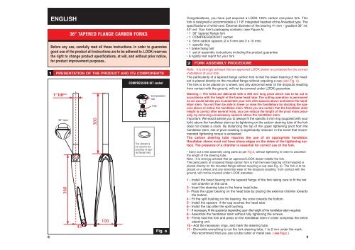
PRESENTATION OF THE PRODUCT AND ITS COMPONENTS<br />
1”1/8 ème<br />
36° taper<br />
COMPRESSION KIT sachet<br />
This element is<br />
not used for the<br />
assembly of tapered<br />
flange forks.<br />
Compression<br />
cap<br />
Cap<br />
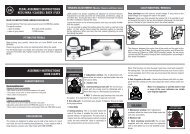
Congratulations, you have just acquired a LOOK 100% carbon one-piece fork. This<br />
fork is designed to accommodate a 1 1/8” integrated headset of the Aheadset type. The<br />
specifications of which are: External diameter of the bearing 41 mm – gradient 36° int,<br />
45° ext. Your fork’s packaging contains: (see Figure A)<br />
• 1 36° tapered flange fork<br />
• 1 COMPRESSION KIT sachet<br />
• 4 5mm carbon spacers (2 x 5 mm and 2 x 10 mm)<br />
• 1 specific ring<br />
• 1 brake fixing bolt<br />
• 1 set of assembly instructions including the product guarantee<br />
• A rigidity test report for your fork<br />
FORK ASSEMBLY PROCEDURE<br />
Fig. a<br />
8 9<br />
2<br />
Note : It is strongly advised that an approved LOOK dealer is contacted for the correct<br />
installation of your fork.<br />
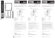
The particularity of a tapered flange carbon fork is that the lower bearing of the headset<br />
is placed directly on the moulded flange without requiring a cup (see Fig. a).<br />
The fork is to be placed on a wheel, and any abnormal wear of the dropouts resulting<br />
from contact with the ground, will not be covered under LOOK guarantee.<br />
Warning !: The forks are delivered with a 300 mm long pivot which has to be cut in<br />
accordance with the height of the frame head tube. The cutting operation is permanent<br />
so we would advise you to assemble your fork with spacers above and below the handlebar<br />
stem. You will then be able to lower or raise the handlebars by stacking the spacers<br />
above or below the handlebar stem. When you are certain that the handlebar stem<br />
height is correct after several trials, you can reduce the height of the pivot more precisely,<br />
by removing unnecessary spacers above the handlebar stem.<br />
Important: We would advise you to always fit the specific 5 mm ring (supplied with your<br />
fork) above the handlebar stem so its tightening on the carbon steering tube of the fork<br />
does not create a crack. By distancing the top of the upper tightening pivot from the<br />
handlebar stem, risk of pivot cracking is significantly reduced in the event that recommended<br />
tightening torque is exceeded.<br />
The carbon steering tube requires the use of an appropriate handlebar.<br />
Handlebar stems must not have sharp edges on the sides of the tightening surface.<br />
The presence of a chamfer is essential for correct use of the fork.<br />
• Carry out a trial assembly using parts as per Fig.b, without tightening in order to ascertain<br />
the length of the steering tube.<br />
Note : It is strongly advised that an approved LOOK dealer installs the fork.<br />
The particularity of a tapered flange carbon fork is that the lower bearing of the headset is<br />
placed directly on the moulded flange without requiring a cup (see Fig. a). The fork is to be<br />
placed on a wheel, and any abnormal wear of the dropouts resulting from contact with the<br />
ground, will not be covered under LOOK warantee.<br />
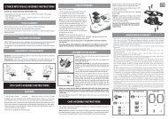
1 - Install the lower bearing on the tapered flange of the fork taking care to fit the bot<br />
tom chamfer on the cone.<br />
2 - Insert the steering tube in the frame head tube.<br />
3 - Place the upper bearing on the head tube by placing the external chamfer towards<br />
the bottom.<br />
4 - Fit the split bushing on the bearing, the cone towards the bottom.<br />
5 - Install the spacers if the cap touches the head tube.<br />
6 - Install the cap after the split bushing.<br />
7 - If necessary, fit the spacer(s) depending upon the height of the handlebar stem required.<br />
8 - Assemble the handlebar stem without fully tightening the screws.<br />
9 - Firmly hold the fork and press on the handlebar stem in order compress the entire<br />
steering unit.<br />
10 - Add the necessary rings, and mark the steering tube.<br />
11 - Dismantle everything to cut the fork steering tube, 1 to 2 mm under the mark.<br />
We recommend that you use a tube cutter or metal saw. ( see Fig.c )