apparecchiatura elettronica per basculanti control board for ... - Faac
apparecchiatura elettronica per basculanti control board for ... - Faac
apparecchiatura elettronica per basculanti control board for ... - Faac

You also want an ePaper? Increase the reach of your titles
YUMPU automatically turns print PDFs into web optimized ePapers that Google loves.
APPARECCHIATURA ELETTRONICA PER BASCULANTI<br />
CONTROL BOARD FOR UP-AND-OVER DOORS<br />
PLATINE ELECTRONIQUE POUR PORTAILS BASCULANTS<br />
EQUIPO ELECTRÓNICO PARA BASCULANTES<br />
ELEKTRONISCHES GERÄT FÜR KIPPTORE<br />
JA668<br />
ISTRUZIONI PER L’USO – NORME DI INSTALLAZIONE<br />
USE AND INSTALLATION INSTRUCTIONS<br />
INSTRUCTIONS POUR L’EMPLOI – NORMES D’INSTALLATION<br />
INSTRUCCIONES PARA EL USO – NORMAS DE INSTALACIÓN<br />
BETRIEBSANLEITUNG - INSTALLATIONSVORSCHRIFTEN
AVVERTENZE PER L’INSTALLATORE<br />
OBBLIGHI GENERALI PER LA SICUREZZA<br />
1) ATTENZIONE! È importante <strong>per</strong> la sicurezza delle <strong>per</strong>sone seguire attentamente<br />
tutta l’istruzione. Una errata installazione o un errato uso del<br />
prodotto può portare a gravi danni alle <strong>per</strong>sone.<br />
2) Leggere attentamente le istruzioni prima di iniziare l’installazione del<br />
prodotto.<br />
3) I materiali dell’imballaggio (plastica, polistirolo, ecc.) non devono<br />
essere lasciati alla portata dei bambini in quanto potenziali fonti di<br />
<strong>per</strong>icolo.<br />
4 ) Conservare le istruzioni <strong>per</strong> riferimenti futuri.<br />
5) Questo prodotto è stato progettato e costruito esclusivamente <strong>per</strong><br />
l’utilizzo indicato in questa documentazione. Qualsiasi altro utilizzo non<br />
espressamente indicato potrebbe pregiudicare l’integrità del prodotto<br />
e/o rappresentare fonte di <strong>per</strong>icolo.<br />
6) GENIUS declina qualsiasi responsabilità derivata dall’uso improprio o<br />
diverso da quello <strong>per</strong> cui l’automatismo è destinato.<br />
7) Non installare l’apparecchio in atmosfera esplosiva: la presenza di<br />
gas o fumi infiammabili costituisce un grave <strong>per</strong>icolo <strong>per</strong> la sicurezza.<br />
8) Gli elementi costruttivi meccanici devono essere in accordo con<br />
quanto stabilito dalle Norme EN 12604 e EN 12605.<br />
Per i Paesi extra-CEE, oltre ai riferimenti normativi nazionali, <strong>per</strong> ottenere<br />
un livello di sicurezza adeguato, devono essere seguite le Norme<br />
sopra riportate.<br />
9) GENIUS non è responsabile dell’inosservanza della Buona Tecnica<br />
nella costruzione delle chiusure da motorizzare, nonché delle<br />
de<strong>for</strong>mazioni che dovessero intervenire nell’utilizzo.<br />
10) L’installazione deve essere effettuata nell’osservanza delle Norme EN<br />
12453 e EN 12445. Il livello di sicurezza dell’automazione deve essere<br />
C+E.<br />
11) Prima di effettuare qualsiasi intervento sull’impianto, togliere l’alimentazione<br />
elettrica.<br />
12) Prevedere sulla rete di alimentazione dell’automazione un interruttore<br />
onnipolare con distanza d’a<strong>per</strong>tura dei contatti uguale o su<strong>per</strong>iore a<br />
3 mm. È consigliabile l’uso di un magnetotermico da 6A con interruzione<br />
onnipolare.<br />
13) Verificare che a monte dell’impianto vi sia un interruttore differenziale<br />
con soglia da 0,03 A.<br />
14) Verificare che l’impianto di terra sia realizzato a regola d’arte e<br />
collegarvi le parti metalliche della chiusura.<br />
15) L’automazione dispone di una sicurezza intrinseca antischiacciamento<br />
costituita da un <strong>control</strong>lo di coppia. E' comunque necessario verificarne<br />
la sogli di intervento secondo quanto previsto dalle Norme indicate<br />
al punto 10.<br />
16) I dispositivi di sicurezza (norma EN 12978) <strong>per</strong>mettono di proteggere<br />
eventuali aree di <strong>per</strong>icolo da Rischi meccanici di movimento, come<br />
ad Es. schiacciamento, convogliamento, cesoiamento.<br />
17) Per ogni impianto è consigliato l’utilizzo di almeno una segnalazione<br />
luminosa nonché di un cartello di segnalazione fissato adeguatamente<br />
sulla struttura dell’infisso, oltre ai dispositivi citati al punto “16”.<br />
18) GENIUS declina ogni responsabilità ai fini della sicurezza e del buon<br />
funzionamento dell’automazione, in caso vengano utilizzati componenti<br />
dell’impianto non di produzione GENIUS.<br />
19) Per la manutenzione utilizzare esclusivamente parti originali GENIUS.<br />
20) Non eseguire alcuna modifica sui componenti facenti parte del<br />
sistema d’automazione.<br />
21) L’installatore deve <strong>for</strong>nire tutte le in<strong>for</strong>mazioni relative al funzionamento<br />
manuale del sistema in caso di emergenza e consegnare all’Utente<br />
utilizzatore dell’impianto il libretto d’avvertenze allegato al prodotto.<br />
22) Non <strong>per</strong>mettere ai bambini o <strong>per</strong>sone di sostare nelle vicinanze del<br />
prodotto durante il funzionamento.<br />
23) Tenere fuori dalla portata dei bambini radiocomandi o qualsiasi altro<br />
datore di impulso, <strong>per</strong> evitare che l’automazione possa essere<br />
azionata involontariamente.<br />
24) Il transito tra le ante deve avvenire solo a cancello completamente<br />
a<strong>per</strong>to.<br />
25) L’Utente utilizzatore deve astenersi da qualsiasi tentativo di riparazione<br />
o d’intervento diretto e rivolgersi solo a <strong>per</strong>sonale qualificato.<br />
26) Tutto quello che non è previsto espressamente in queste istruzioni non è<br />
<strong>per</strong>messo<br />
IMPORTANT NOTICE FOR THE INSTALLER<br />
GENERAL SAFETY REGULATIONS<br />
1) ATTENTION! To ensure the safety of people, it is important that you read<br />
all the following instructions. Incorrect installation or incorrect use of the<br />
product could cause serious harm to people.<br />
2) Carefully read the instructions be<strong>for</strong>e beginning to install the product.<br />
3) Do not leave packing materials (plastic, polystyrene, etc.) within<br />
reach of children as such materials are potential sources of danger.<br />
4 ) Store these instructions <strong>for</strong> future reference.<br />
5) This product was designed and built strictly <strong>for</strong> the use indicated in this<br />
documentation. Any other use, not expressly indicated here, could<br />
compromise the good condition/o<strong>per</strong>ation of the product and/or be<br />
a source of danger.<br />
6) GENIUS declines all liability caused by impro<strong>per</strong> use or use other than<br />
that <strong>for</strong> which the automated system was intended.<br />
7) Do not install the equipment in an explosive atmosphere: the presence<br />
of inflammable gas or fumes is a serious danger to safety.<br />
8) The mechanical parts must con<strong>for</strong>m to the provisions of Standards EN<br />
12604 and EN 12605.<br />
For non-EU countries, to obtain an adequate level of safety, the<br />
Standards mentioned above must be observed, in addition to national<br />
legal regulations.<br />
9) GENIUS is not responsible <strong>for</strong> failure to observe Good Technique in the<br />
construction of the closing elements to be motorised, or <strong>for</strong> any<br />
de<strong>for</strong>mation that may occur during use.<br />
10) The installation must con<strong>for</strong>m to Standards EN 12453 and EN 12445. The<br />
safety level of the automated system must be C+E.<br />
11) Be<strong>for</strong>e attempting any job on the system, cut out electrical power.<br />
12) The mains power supply of the automated system must be fitted with<br />
an all-pole switch with contact opening distance of 3mm or greater.<br />
Use of a 6A thermal breaker with all-pole circuit break is recommended.<br />
13) Make sure that a differential switch with threshold of 0.03 A is fitted<br />
upstream of the system.<br />
14) Make sure that the earthing system is <strong>per</strong>fectly constructed, and<br />
connect metal parts of the means of the closure to it.<br />
15) The automated system is supplied with an intrinsic anti-crushing safety<br />
device consisting of a torque <strong>control</strong>. Nevertheless, its tripping threshold<br />
must be checked as specified in the Standards indicated at point 10.<br />
16) The safety devices (EN 12978 standard) protect any danger areas<br />
against mechanical movement Risks, such as crushing, dragging, and<br />
shearing.<br />
17) Use of at least one indicator-light is recommended <strong>for</strong> every system,<br />
as well as a warning sign adequately secured to the frame structure,<br />
in addition to the devices mentioned at point “16”.<br />
18) GENIUS declines all liability as concerns safety and efficient o<strong>per</strong>ation<br />
of the automated system, if system components not produced by<br />
GENIUS are used.<br />
19) For maintenance, strictly use original parts by GENIUS.<br />
20) Do not in any way modify the components of the automated system.<br />
21) The installer shall supply all in<strong>for</strong>mation concerning manual o<strong>per</strong>ation<br />
of the system in case of an emergency, and shall hand over to the<br />
user the warnings handbook supplied with the product.<br />
22) Do not allow children or adults to stay near the product while it is<br />
o<strong>per</strong>ating.<br />
23) Keep remote <strong>control</strong>s or other pulse generators away from children,<br />
to prevent the automated system from being activated involuntarily.<br />
24) Transit through the leaves is allowed only when the gate is fully open.<br />
25) The user must not attempt any kind of repair or direct action whatever<br />
and contact qualified <strong>per</strong>sonnel only.<br />
26) Anything not expressly specified in these instructions is not <strong>per</strong>mitted.<br />
CONSIGNES POUR L'INSTALLATEUR<br />
RÈGLES DE SÉCURITÉ<br />
1) ATTENTION! Il est important, pour la sécurité des <strong>per</strong>sonnes, de suivre à<br />
la lettre toutes les instructions. Une installation erronée ou un usage erroné<br />
du produit peut entraîner de graves conséquences pour les <strong>per</strong>sonnes.<br />
2) Lire attentivement les instructions avant d'installer le produit.<br />
3) Les matériaux d'emballage (matière plastique, polystyrène, etc.) ne<br />
doivent pas être laissés à la portée des enfants car ils constituent des<br />
sources potentielles de danger.<br />
4) Conserver les instructions pour les références futures.<br />
5) Ce produit a été conçu et construit exclusivement pour l'usage<br />
indiqué dans cette documentation. Toute autre utilisation non<br />
expressément indiquée pourrait compromettre l'intégrité du produit<br />
et/ou représenter une source de danger.<br />
6) GENIUS décline toute responsabilité qui dériverait d'usage impropre<br />
ou différent de celui auquel l'automatisme est destiné.<br />
7) Ne pas installer l'appareil dans une atmosphère explosive: la présence<br />
de gaz ou de fumées inflammables constitue un grave danger pour<br />
la sécurité.<br />
8) Les composants mécaniques doivent répondre aux prescriptions des<br />
Normes EN 12604 et EN 12605.<br />
Pour les Pays extra-CEE, l'obtention d'un niveau de sécurité approprié<br />
exige non seulement le respect des normes nationales, mais<br />
également le respect des Normes susmentionnées.<br />
9) GENIUS n'est pas responsable du non-respect de la Bonne Technique<br />
dans la construction des fermetures à motoriser, ni des dé<strong>for</strong>mations<br />
qui pourraient intervenir lors de l'utilisation.<br />
10) L'installation doit être effectuée con<strong>for</strong>mément aux Normes EN 12453<br />
et EN 12445. Le niveau de sécurité de l'automatisme doit être C+E.<br />
11) Cou<strong>per</strong> l'alimentation électrique avant toute intervention sur l'installation.<br />
12) Prévoir, sur le secteur d'alimentation de l'automatisme, un interrupteur<br />
omnipolaire avec une distance d'ouverture des contacts égale ou<br />
supérieure à 3 mm. On recommande d'utiliser un magnétothermique<br />
de 6A avec interruption omnipolaire.<br />
13) Vérifier qu'il y ait, en amont de l'installation, un interrupteur différentiel<br />
avec un seuil de 0,03 A.<br />
14) Vérifier que la mise à terre est réalisée selon les règles de l'art et y<br />
connecter les pièces métalliques de la fermeture.<br />
15) L'automatisme dispose d'une sécurité intrinsèque anti-écrasement,<br />
<strong>for</strong>mée d'un contrôle du couple. Il est toutefois nécessaire d'en vérifier<br />
le seuil d'intervention suivant les prescriptions des Normes indiquées au<br />
point 10.<br />
16) Les dispositifs de sécurité (norme EN 12978) <strong>per</strong>mettent de protéger<br />
des zones éventuellement dangereuses contre les Risques mécaniques<br />
du mouvement, comme l'écrasement, l'acheminement, le<br />
cisaillement.
APPARECCHIATURA ELETTRONICA PER BASCULANTI<br />
ISTRUZIONI PER L’USO - NORME DI INSTALLAZIONE<br />
ITALIANO<br />
1. CARATTERISTICHE GENERALI<br />
Questa centrale di comando <strong>per</strong> <strong>basculanti</strong>, grazie alla elevata potenza del microprocessore di cui è dotata, offre un<br />
ampio numero di prestazioni e regolazioni, con rallentamento e <strong>control</strong>lo motore. Inoltre garantisce un elevato livello<br />
di sicurezza attiva , mediante il <strong>control</strong>lo elettronico di potenza. Un sofisticato <strong>control</strong>lo elettronico monitorizza<br />
costantemente il circuito di potenza ed interviene bloccando la centrale in caso di anomalie che possano pregiudicare<br />
il corretto funzionamento della frizione <strong>elettronica</strong>.<br />
I settaggi principali e i modi di funzionamento, le regolazioni dei tempi e della potenza del motore si effettuano<br />
mediante dip-switch.<br />
2. CARATTERISTICHE TECNICHE<br />
2.1 CARATTERISTICHE HARDWARE<br />
Alimentazione<br />
230VAC - 50Hz<br />
Potenza max assorbita<br />
12VA<br />
Carico max motori<br />
800W<br />
Alimentazione accessori<br />
24Vdc<br />
Carico max accessori<br />
300mA<br />
Tem<strong>per</strong>atura ambiente - 20°C + 55°C<br />
Fusibili di protezione<br />
circuito rete / accessori<br />
Connettore rapido<br />
<strong>per</strong> schede decodifica o riceventi RP a 5 Pin<br />
Morsettiere<br />
estraibili<br />
Ingressi in morsettiera<br />
Open / Stop / Sicurezze in chiusura / Sicurezze in a<strong>per</strong>tura/<br />
Finecorsa a<strong>per</strong>tura/Finecorsa chiusura<br />
Uscite in morsettiera lampeggiatore 230VAC - 40W /motore /<br />
lampada di cortesia esterna 230VAC - 25W /<br />
alimentazione accessori 24Vdc<br />
Carico max lampada cortesia incorporata<br />
25W<br />
Carico max lampada cortesia esterna<br />
25W<br />
2.2 PARAMETRI DI FUNZIONAMENTO<br />
Logica<br />
automatica/semiautomatica<br />
Tempo pausa<br />
programmabile da 0 a 60 sec.<br />
Tempo lavoro<br />
programmabile da 17 a 30 sec.<br />
Coppia max allo spunto<br />
fisso 0.5 sec.<br />
Fail safe<br />
Si/No<br />
Prelampeggio<br />
Si ( 5 sec.) / No<br />
Frizione <strong>elettronica</strong><br />
programmabile su 8 livelli<br />
Modalità intervento finecorsa 4 tipologie di funzionamento<br />
Temporizzazione di cortesia<br />
fisso 60 sec.<br />
<br />
<br />
<br />
<br />
<br />
<br />
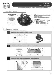
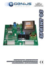
3. LAY OUT SCHEDA (fig.1)<br />
F1 Fusibile F1 5x20 5A/250V (circuito rete)<br />
F2 Fusibile F2 5x20 500mA/250V (accessori)<br />
TF1 Tras<strong>for</strong>matore<br />
LP1 Lampada di cortesia 25W 230V E14<br />
LD1 Led alimentazione<br />
J1 Morsettiera ingresso alimentazione 230VAC<br />
J2 Morsettiera uscita motore, lampeggiatore e lamp. cortesia ext.<br />
J3 Morsettiera bassa tensione ingressi/accessori<br />
J4 Connettore rapido schede decodifica/riceventi RP 5 Pin<br />
DS1 Microinterruttori di programmazione<br />
<br />
<br />
<br />
<br />
<br />
<br />
<br />
<br />
Fig. 1<br />
1
ITALIANO<br />
4. COLLEGAMENTO SCHEDA ELETTRONICA<br />
Prima di effettuare qualsiasi tipo di intervento sulla scheda (collegamenti, programmazione, manutenzione)<br />
togliere sempre l’alimentazione elettrica.<br />
Attenzione: Scollegando la morsettiera J2 può essere presente alta tensione.<br />
Seguire i punti 10, 11, 12, 13,14 degli OBBLIGHI GENERALI PER LA SICUREZZA.<br />
Separare sempre i cavi di alimentazione da quelli di comando e di sicurezza (pulsante, ricevente, fotocellule ecc.). Per<br />
evitare qualsiasi disturbo elettrico utilizzare guaine separate.<br />
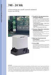
Per i collegamenti far riferimento alle fig. 2 e 3<br />
4.1 MORSETTIERA J1 (alta tensione)<br />
PE-N-L Alimentazione 230V~ 50Hz<br />
Morsettiera <strong>per</strong> l'alimentazione 230V~ 50Hz (L= Fase N=Neutro).<br />
Collegare la terra dell'impianto elettrico e il cavo di terra<br />
dell'o<strong>per</strong>atore nel morsetto "PE".<br />
4.2 MORSETTIERA J2 (alta tensione)<br />
11-12-13 Com-OP-CL = Motore<br />
Morsettiera 230V~ <strong>per</strong> il collegamento del motore: ai morsetti 12<br />
e 13 vanno collegate le fasi del motore (cavi Nero e Marrone),<br />
mentre al morsetto 11 si deve collegare il comune (cavo Blu).Il<br />
condensatore di spunto va collegato in parallelo alle fasi.<br />
14-16 Lampada di cortesia<br />
Morsettiera 230V~ <strong>per</strong> il collegamento della lampada di<br />
cortesia: collegare tra i morsetti 14 e 16 la lampada di cortesia<br />
della seconda basculante oppure una lampada di cortesia<br />
esterna con potenza max. 25W.<br />
15-16 Lampeggiatore<br />
Morsettiera 230V~ <strong>per</strong> il collegamento del lampeggiatore:<br />
collegare tra i morsetti 15 e 16 un lampeggiatore con potenza<br />
max. 40W.<br />
4.3 MORSETTIERA J3 (bassa tensione)<br />
1 Comune ingressi/Negativo alimentazione accessori<br />
2 Comune ingressi/Negativo alimentazione accessori<br />
3 Positivo alimentazione accessori 24Vdc (+)<br />
Il carico max degli accessori è di 300mA .<br />
Per il calcolo degli assorbimenti, fare riferimento alle istruzioni<br />
dei singoli accessori.<br />
4 -FSW TX = Negativo alimentazione trasmettitori fotocellule<br />
Il collegamento separato del negativo dei trasmettitori,<br />
<strong>per</strong>mette di utilizzare il <strong>control</strong>lo Failsafe sulle fotocellule,<br />
aumentando il livello di sicurezza dell'impianto.<br />
5 FCA = Contatto Finecorsa a<strong>per</strong>tura (N.C.)<br />
Il finecorsa di a<strong>per</strong>tura (opzionale) è costituito da un<br />
micropulsante che, azionato dalla camma quando la porta<br />
raggiunge la posizione di a<strong>per</strong>to, arresta il movimento immediatamente.<br />
Nota bene: se non vengono collegati dispositivi di finecorsa,<br />
ponticellare "FCC" e "FCA" col Comune ingressi.<br />
6 FCC = Contatto Finecorsa chiusura (N.C.)<br />
Il finecorsa di chiusura (opzionale) è costituito da un<br />
micropulsante che, azionato dalla camma quando la porta<br />
raggiunge la posizione di chiuso, esegue un movimento, in base<br />
alla programmazione effettuata ai microinterruttori relativi.<br />
Nota bene: se non vengono collegati dispositivi di finecorsa,<br />
ponticellare "FCC" e "FCA" col Comune ingressi.<br />
<br />
<br />
<br />
<br />
<br />
<br />
<br />
<br />
<br />
<br />
<br />
<br />
<br />
<br />
<br />
<br />
<br />
<br />
<br />
<br />
<br />
<br />
<br />
<br />
<br />
<br />
<br />
<br />
<br />
<br />
<br />
<br />
<br />
<br />
<br />
<br />
<br />
<br />
<br />
<br />
<br />
<br />
<br />
<br />
<br />
<br />
<br />
<br />
<br />
<br />
<br />
<br />
<br />
<br />
<br />
<br />
<br />
<br />
<br />
<br />
<br />
<br />
<br />
<br />
<br />
<br />
<br />
<br />
<br />
<br />
Fig. 2<br />
Fig. 3<br />
2
3<br />
ITALIANO<br />
7 FSW OP = Contatto Sicurezze in A<strong>per</strong>tura (N.C.)<br />
Per sicurezze si intendono tutti i dispositivi (fotocellule, coste sensibili, ...) con contatto N.C. che in presenza di un<br />
ostacolo nell’area da loro protetta, intervengono arrestando o invertendo il movimento di a<strong>per</strong>tura della<br />
porta.<br />
Non hanno effetto durante la fase di chiusura.<br />
Le sicurezze in a<strong>per</strong>tura, se impegnate a porta chiusa, inibiscono qualsiasi impulso di Open.<br />
Per installare più dispositivi di sicurezza, collegare i contatti N.C. in serie.<br />
Nota bene: se non vengono collegati dispositivi di sicurezza in a<strong>per</strong>tura, ponticellare gli ingressi "FSW OP" e "-<br />
FSW TX".<br />
8 FSW CL = Contatto Sicurezze in Chiusura (N.C.)<br />
Per sicurezze si intendono tutti i dispositivi (fotocellule, coste sensibili, ...) con contatto N.C. che in presenza di un<br />
ostacolo nell’area da loro protetta, intervengono invertendo il movimento di chiusura della porta.<br />
Non hanno effetto durante la fase di a<strong>per</strong>tura.<br />
Le sicurezze in chiusura, se impegnate a porta a<strong>per</strong>ta, inibiscono qualsiasi impulso di Open.<br />
Per installare più dispositivi di sicurezza, collegare i contatti N.C. in serie.<br />
Nota bene: se non vengono collegati dispositivi di sicurezza in chiusura, ponticellare gli ingressi "FSW CL" e "-<br />
FSW TX".<br />
9 STOP = Comando di STOP (N.C.)<br />
Viene così indicato qualsiasi dispositivo (es. pulsante) che, aprendo un contatto, arresta il movimento della<br />
porta.<br />
Per installare più dispositivi d’arresto, collegare i contatti N.C. in serie.<br />
Nota bene: se non vengono collegati dispositivi di Stop, ponticellare "STOP" col Comune ingressi.<br />
10 OPEN = Comando di OPEN (N.A.)<br />
Viene così indicato qualsiasi dispositivo (pulsante, detector,..) che, chiudendo un contatto, dà un impulso<br />
d’a<strong>per</strong>tura (o chiusura) alla porta.<br />
Per installare più dispositivi di Open, collegare i contatti N.A. in parallelo.<br />
4.4 CONNETTORE J4 (bassa tensione)<br />
Il connettore J4 è utilizzato <strong>per</strong> il collegamento rapido di schede MINIDEC, DECODER, RICEVENTI RP a 5 pin.<br />
L'inserimento avviene innestando le schede accessorie in maniera che il loro lato componenti sia rivolto verso l'interno<br />
della scheda.<br />
Inserimento e disinserimento vanno effettuati dopo aver tolto tensione.<br />
5. LED DI SEGNALAZIONE<br />
Sulla scheda è presente un led LD1 che segnala la corretta alimentazione della centrale.<br />
LED ACCESO = centrale alimentata<br />
LED SPENTO = centrale non alimentata<br />
6. PROGRAMMAZIONE<br />
Per programmare il funzionamento dell'automazione è necessario impostare i microinterrutori DS1 presenti sulla<br />
scheda. Di seguito sono riportate le descrizioni e tabelle relative ai vari settaggi e la tipo di funzione relativa (fig. 4 e 5).<br />
6.1 TEMPO LAVORO<br />
Impostare con i microinteruttori SW1 e SW2 un tempo di lavoro<br />
che <strong>per</strong>metta di mantenere il motore elettrico alimentato <strong>per</strong><br />
qualche secondo dopo l'arrivo della porta sugli arresti<br />
meccanici. Questa regolazione rappresenta anche il tempo<br />
massimo <strong>per</strong> raggiungere i finecorsa elettrici in a<strong>per</strong>tura e<br />
chiusura (opzionali), se vengono vengono utilizzati.<br />
6.2 LOGICA DI FUNZIONAMENTO E TEMPI DI<br />
PAUSA<br />
E' possibile regolare <strong>per</strong> mezzo dei microinterruttori SW3, SW4 e<br />
SW5 il tempo di pausa se si utilizza la logica Automatica.<br />
6.3 FRIZIONE ELETTRONICA<br />
L'<strong>apparecchiatura</strong> è <strong>for</strong>nita di un sistema elettronico di<br />
regolazione della coppia del motore che (in funzione della<br />
regolazione stessa) limita la spinta della porta in presenza di un<br />
ostacolo. Alla rimozione dell'ostacolo, la porta prosegue il<br />
movimento fino al raggiungimento del fine corsa o fino al<br />
termine del tempo di lavoro. Si raccomanda di tarare con i<br />
microinterruttori SW6, SW7 e SW8 la frizione <strong>elettronica</strong> in<br />
con<strong>for</strong>mità alle normative vigenti.<br />
SW1 SW2 Tempo lavoro<br />
on on 30 sec.<br />
off on 25 sec.<br />
on off 20 sec.<br />
off off 17 sec.<br />
Fig. 4<br />
<br />
<br />
SW6 SW7 SW8 Forza<br />
on on on min<br />
off on on<br />
on off on<br />
off off on<br />
on on off<br />
off on off<br />
on off off<br />
off off off max<br />
<br />
SW3 SW4 SW5 Logica Tempo pausa<br />
on on on semiautomatica<br />
off on on automatica 5 sec.<br />
on off on automatica 10 sec.<br />
off off on automatica 15 sec.<br />
on on off automatica 20 sec.<br />
off on off automatica 30 sec.<br />
on off off automatica 45 sec.<br />
off off off automatica 60 sec.
ITALIANO<br />
6.4 FAIL SAFE<br />
La programmazione del microinterruttore SW9<br />
<strong>per</strong>mette di attifare o disttivare la funzione Fail safe,<br />
che verifica ad ogni attivazione il corretto funzionamento<br />
dei dispositivi di sicurezza installati, se alimentati<br />
con l'apposito contatto previsto in morsettiera.<br />
6.5 PRELAMPEGGIO<br />
E' possibile selezionare con il microinterruttore SW10 un<br />
prelampeggio di 5 secondi prima della<br />
movimentazione della porta.<br />
6.6 LOGICA DI FUNZIONAMENTO<br />
FINECORSA CHIUSURA<br />
E' possibile selezionare <strong>per</strong> mezzo dei microinterruttori<br />
SW11 e SW12 quattro diverse modalità di funzionamento<br />
del finecorsa di chiusura.<br />
Questo settaggio non ha nessun effetto sul finecorsa di<br />
a<strong>per</strong>tura, che arresta immediatamente.<br />
SW9 Fail safe<br />
on attivo<br />
off escluso<br />
Fig. 5<br />
<br />
<br />
<br />
SW10 Prelampeggio<br />
on attivo<br />
off escluso<br />
SW11 SW12 Logica<br />
on on arresta immediatamente<br />
off on rallenta <strong>per</strong> 5 sec.<br />
on off continua a velocità piena <strong>per</strong> 5 sec.<br />
off off rallenta <strong>per</strong> 4 sec. + 1 sec. finale a velocità piena<br />
7. EFFETTO DEGLI INGRESSI NEI DIVERSI STATI DELLA PORTA<br />
7.1 LOGICA AUTOMATICA<br />
IMPULSI<br />
STATO PORTA<br />
CHIUSA<br />
APERTA IN<br />
PAUSA<br />
IN CHIUSURA<br />
IN APERTURA<br />
BLOCCATA<br />
7.2 LOGICA SEMIAUTOMATICA<br />
IMPULSI<br />
STATO PORTA<br />
CHIUSA<br />
APERTA<br />
IN CHIUSURA<br />
IN APERTURA<br />
BLOCCATA<br />
OPEN<br />
apre e richiude dopo il<br />
tempo di pausa (1)<br />
riconta il<br />
tempo pausa<br />
inverte il moto<br />
nessun effetto<br />
chiude (1)<br />
OPEN<br />
apre (1)<br />
chiude (1)<br />
inverte il moto<br />
blocca<br />
chiude (1)<br />
STOP<br />
nessun effetto<br />
(inibisce a<strong>per</strong>tura)<br />
blocca il conteggio<br />
del tempo pausa<br />
blocca<br />
blocca<br />
nessun effetto<br />
(inibisce chiusura)<br />
STOP<br />
nessun effetto<br />
(inibisce a<strong>per</strong>tura)<br />
nessun effetto<br />
(inibisce chiusura)<br />
blocca<br />
blocca<br />
nessun effetto<br />
(inibisce chiusura)<br />
(1) con prelampeggio selezionato, il movimento inizia dopo il tempo di prelampeggio.<br />
8. PROVA DELL'AUTOMAZIONE<br />
SICUREZZE CHIUSURA<br />
nessun effetto<br />
nessun effetto<br />
(inibisce chiusura)<br />
inverte il moto<br />
nessun effetto<br />
nessun effetto<br />
(inibisce chiusura)<br />
SICUREZZE CHIUSURA<br />
nessun effetto<br />
nessun effetto<br />
inverte il moto<br />
nessun effetto<br />
nessun effetto<br />
(inibisce chiusura)<br />
La scheda esegue un <strong>control</strong>lo elettronico (che richiede la presenza del motore collegato) prima di ogni partenza. Se<br />
si tenta di far funzionare la scheda senza il carico del motore o con un carico insufficiente, non viene <strong>for</strong>nita tensione<br />
sull'uscita motore.<br />
Verificare il corretto senso di rotazione:<br />
1) Togliere alimentazione all'impianto.<br />
2) Portare manualmente la porta a metà a<strong>per</strong>tura.<br />
3) Bloccare l'o<strong>per</strong>atore<br />
4) Ripristinare la tensione di alimentazione.<br />
5) Inviare un impulso di a<strong>per</strong>tura (OPEN) e verificare che il motore esegua un'a<strong>per</strong>tura della porta.<br />
Nel caso si verifichi una chiusura, è necessario invertire sulla morsettiera della scheda le fasi del motore elettrico (cavi<br />
marrone e nero).<br />
4<br />
SICUREZZE APERTURA<br />
nessun effetto<br />
(inibisce a<strong>per</strong>tura)<br />
nessun effetto<br />
nessun effetto<br />
inverte il moto<br />
nessun effetto<br />
SICUREZZE APERTURA<br />
nessun effetto<br />
(inibisce a<strong>per</strong>tura)<br />
nessun effetto<br />
nessun effetto<br />
inverte il moto<br />
nessun effetto
CONTROL BOARD FOR UP-AND-OVER DOORS<br />
INSTRUCTIONS FOR USE- DIRECTIONS FOR INSTALLATION<br />
1. GENERAL FEATURES<br />
5<br />
ENGLISH<br />
Thanks to the high-power <strong>per</strong><strong>for</strong>mance of its built-in microprocessor, this <strong>control</strong> unit <strong>for</strong> up-and-over doors offers a wide<br />
number of services and adjustments, with slowdown and motor <strong>control</strong>. It also guarantees a high active safety level through<br />
electronic power <strong>control</strong>.<br />
A sophisticated electronic <strong>control</strong> constantly monitors the power circuit and blocks the <strong>control</strong> unit if faults occur which<br />
may cause the electronic clutch to o<strong>per</strong>ate incorrectly.<br />
The main settings and o<strong>per</strong>ating modes, time and motor power adjustments can be defined using dip-switches .<br />
2. TECHNICAL SPECIFICATIONS<br />
2.1 HARDWARE SPECIFICATIONS<br />
Power supply<br />
230VAC - 50Hz<br />
Max. absorbed power<br />
12VA<br />
Motors max. load<br />
800W<br />
Power supply <strong>for</strong> accessories<br />
24Vdc<br />
Accessories max. load<br />
300mA<br />
O<strong>per</strong>ating ambient tem<strong>per</strong>ature - 20°C + 55°C<br />
Protection fuses<br />
mains circuit / accessories<br />
Rapid connector<br />
<strong>for</strong> decoding cards or 5-Pin RP receivers<br />
Terminal <strong>board</strong>s<br />
pull-out<br />
Terminal <strong>board</strong> inputs Open / Stop / Closing safety devices / Opening safety devices /<br />
Opening limit-switch / Closing limit-switch<br />
Terminal <strong>board</strong> outputs flashing lamp 230VAC - 40W /motor /<br />
outside courtesy lamp 230VAC - 25W /<br />
24 Vdc accessories power supply<br />
Max. load of built-in courtesy lamp<br />
25W<br />
Max. load of outside courtesy lamp<br />
25W<br />
2.2 OPERATING PARAMETERS<br />
Logic<br />
automatic/semi-automatic<br />
Pause time<br />
Max torque at thrust<br />
programmable from 0 to 60 sec.<br />
fixed 0.5 sec.<br />
O<strong>per</strong>ating time<br />
Fail safe<br />
programmable from 17 to 30 sec.<br />
Yes/No<br />
<br />
<br />
Pre-flashing<br />
Yes ( 5 sec.) / No<br />
<br />
Electronic clutch<br />
programmable on 8 levels<br />
Limit-switch tripping modes 4 types of o<strong>per</strong>ation<br />
Courtesy timer<br />
fixed 60 sec.<br />
3. LAY OUT OF CONTROL BOARD (fig.1)<br />
F1 Fuse F1 5x20 5A/250V (mains circuit)<br />
F2 Fuse F2 5x20 500mA/250V (accessories)<br />
TF1 Trans<strong>for</strong>mer<br />
LP1 Courtesy lamp 25W 230V E14<br />
LD1 Power-supply Led<br />
J1 230VAC power supply input terminal <strong>board</strong><br />
J2<br />
J3 Low voltage input/accessories terminal <strong>board</strong><br />
J4 Rapid connector <strong>for</strong> decoding cards / 5-Pin RP receivers<br />
DS1 Programming microswitches<br />
Motor output terminal <strong>board</strong>, flashing lamp and outside courtesy lamp<br />
<br />
<br />
<br />
<br />
<br />
<br />
<br />
<br />
<br />
<br />
<br />
Fig. 1
ENGLISH<br />
4. CONTROL BOARD CONNECTION<br />
Be<strong>for</strong>e attempting any work on the <strong>control</strong> <strong>board</strong> (connections, programming, maintenance), always turn off<br />
power.<br />
Important: High voltage could be present when disconnecting the J2 terminal <strong>board</strong>.<br />
Observe points 10, 11, 12, 13 and 14 of the GENERAL SAFETY OBLIGATIONS.<br />
Always separate power cables from <strong>control</strong> and safety cables (push-button, receiver, photocells, etc.). To prevent any<br />
electric noise whatever, use separate sheaths.<br />
For connections, refer to fig. 2 and 3<br />
4.1 TERMINAL BOARD J1 (high voltage)<br />
PE-N-L 230V~ 50Hz Power supply<br />
Terminal <strong>board</strong> <strong>for</strong> power supply 230V~ 50Hz (L= Phase<br />
N=Neutral). Connect the earth wire of the electric system and<br />
the earth wire of the o<strong>per</strong>ator to the "PE" terminal.<br />
4.2 TERMINAL BOARD J2 (high voltage)<br />
11-12-13 Com-OP-CL = Motor<br />
230V~ terminal <strong>board</strong> <strong>for</strong> connection of motor: connect motor<br />
phases (Black and Brown wires) to the terminals 12 and 13,<br />
connect the common (Blue wire) to the terminal 11. Connect the<br />
thrust capacitor in parallel to the phases.<br />
14-16 Courtesy lamp<br />
230V~ terminal <strong>board</strong> <strong>for</strong> connection of courtesy lamp: connect<br />
the courtesy lamp of the second up-and-over door or the<br />
outside courtesy lamp with max power of 25W between terminals<br />
14 and 16.<br />
15-16 Flashing lamp<br />
230V~ terminal <strong>board</strong> <strong>for</strong> connection of flashing lamp: connect<br />
a flashing lamp with max. power of 40W between terminals 15<br />
and 16.<br />
4.3 TERMINAL BOARD J3 (low voltage)<br />
1 Accessories supply input/Negative common.<br />
2 Accessories supply input/Negative common.<br />
3 Positive <strong>for</strong> powering 24 Vdc (+) accessories<br />
Max. load of accessories: 300 mA.<br />
To calculate absorption values, refer to the instructions <strong>for</strong><br />
individual accessories.<br />
4 -FSW TX = Negative <strong>for</strong> power supply to photocell<br />
transmitters.<br />
Separate connection of the transmitters negative enables use of<br />
Failsafe <strong>control</strong> on the photocells, thus increasing the system's<br />
safety level.<br />
5 FCA = Opening limit-switch contact (N.C.)<br />
The opening limit-switch (optional) consists of a microswitch<br />
which, when activated by the cam as the door reaches open<br />
position, stops movement immediately.<br />
Note: If limit-switch devices are not connected, jum<strong>per</strong> connect<br />
"FCC" and "FCA" to the inputs Common.<br />
6 FCC = Closing limit-switch contact (N.C.)<br />
The closing limit-switch (optional) consists of a microswitch which,<br />
when activated by the cam as the door reaches closed position,<br />
<strong>per</strong><strong>for</strong>ms a movement according to microswitches<br />
programming.<br />
Note: If limit-switch devices are not connected, jum<strong>per</strong> connect<br />
"FCC" and "FCA" to the inputs Common.<br />
<br />
<br />
<br />
<br />
<br />
<br />
<br />
<br />
<br />
<br />
<br />
<br />
<br />
<br />
<br />
<br />
<br />
<br />
<br />
<br />
<br />
<br />
<br />
<br />
<br />
<br />
<br />
<br />
<br />
<br />
<br />
<br />
<br />
<br />
<br />
<br />
<br />
<br />
<br />
<br />
<br />
<br />
<br />
<br />
<br />
<br />
<br />
<br />
<br />
<br />
<br />
<br />
<br />
<br />
<br />
<br />
<br />
<br />
<br />
<br />
<br />
<br />
<br />
<br />
<br />
<br />
<br />
<br />
<br />
<br />
Fig. 2<br />
6<br />
Fig. 3
ENGLISH<br />
7 FSW OP = Opening safety devices contact (N.C.)<br />
Safety devices are all devices (photocells, sensitive edges,...) with N.C. contact, which, if there is an obstacle in<br />
the area they protect, o<strong>per</strong>ate to stop or reverse door opening movement.<br />
They have no effect during closing.<br />
If the opening safety devices are engaged with the door closed, they inhibit any Open pulse.<br />
To install several safety devices, connect the N.C. contacts in series.<br />
Note: If opening safety devices are not connected, jum<strong>per</strong> connect inputs "FSW OP" and "-FSW TX".<br />
8 FSW CL = Closing safety devices contact (N.C.)<br />
Safety devices are all devices (photocells, sensitive edges,...) with N.C. contact, which, if there is an obstacle in<br />
the area they protect, o<strong>per</strong>ate to reverse door closing movement.<br />
They have no effect at opening.<br />
If the closing safety devices are engaged with the door open, they inhibit any Open pulse.<br />
To install several safety devices, connect the N.C. contacts in series.<br />
Note: If closing safety devices are not connected, jum<strong>per</strong> connect inputs "FSW CL" and "-FSW TX".<br />
9 STOP = STOP Command (N.C.)<br />
This is any device (e.g. a push-button) which, by opening a contact, stops door movement.<br />
To install several stop devices, connect the N.C. contacts in series.<br />
Note: If Stop devices are not connected, jum<strong>per</strong> connect “STOP” to the inputs Common.<br />
10 OPEN = OPEN Command (N.O.)<br />
This is any device (a push-button, a detector,...) which, by closing a contact, supplies an opening (or closing)<br />
pulse to the door.<br />
To install several Open devices, connect N.O. contacts in parallel.<br />
4.4 CONNECTOR J4 (low voltage)<br />
Connector J4 is used <strong>for</strong> rapid connection of MINIDEC, DECODER cards and 5-Pin RP RECEIVERS.<br />
Install by fitting the auxiliary cards so that their components side faces the inside of the <strong>control</strong> <strong>board</strong>.<br />
Insert and remove the cards after cutting power.<br />
5. SIGNALLING LEDs<br />
An LD1 led on the <strong>control</strong> <strong>board</strong> signals the correct power suppy to the <strong>control</strong> <strong>board</strong>.<br />
LED LIGHTED = powered <strong>control</strong> unit LED OFF = unpowered <strong>control</strong> unit<br />
6. PROGRAMMING<br />
To program o<strong>per</strong>ation of the automated system, you have to set the microswitches DS1 on the <strong>control</strong> <strong>board</strong>.<br />
Descriptions and tables <strong>for</strong> different settings and type of function (fig. 4 and 5) are shown below.<br />
6.1 OPERATING TIME<br />
Use microswitches SW1 and SW2 to set an o<strong>per</strong>ating time enabling the electric motor to receive power <strong>for</strong> a few<br />
seconds after the door reaches the mechanical stops. This setting is also the maximum time <strong>for</strong> reaching the electric<br />
opening and closing limit-switches (optional), if used.<br />
6.2 OPERATING LOGIC AND PAUSE TIMES<br />
You can adjust the pause time through the microswitches SW3,<br />
SW4 and SW5 if you use the Automatic logic.<br />
6.3 ELECTRONIC CLUTCH<br />
The <strong>control</strong> <strong>board</strong> is supplied with an electronic system <strong>for</strong><br />
adjusting motor torque, which (according to adjustment)limits<br />
door thrust in the event of any obstacles. After the obstacle is<br />
removed, the door resumes moving either until it reaches the<br />
limit-switch or when o<strong>per</strong>ating time has elapsed. We recommend<br />
setting the electronic clutch with microswitches SW6,SW7 and<br />
SW8 in compliance with current standards.<br />
SW1 SW2 O<strong>per</strong>ating time<br />
on on 30 sec.<br />
off on 25 sec.<br />
on off 20 sec.<br />
off off 17 sec.<br />
Fig. 4<br />
<br />
<br />
SW6 SW7 SW8 Force<br />
on on on min<br />
off on on<br />
on off on<br />
off off on<br />
on on off<br />
off on off<br />
on off off<br />
off off off max<br />
<br />
SW3 SW4 SW5 Logic Pause time<br />
on on on semi-automatic<br />
off on on automatic 5 sec.<br />
on off on automatic 10 sec.<br />
off off on automatic 15 sec.<br />
on on off automatic 20 sec.<br />
off on off automatic 30 sec.<br />
on off off automatic 45 sec.<br />
off off off automatic 60 sec.<br />
7
ENGLISH<br />
6.4 FAIL SAFE<br />
Programming the microswitch SW9 enables to activate<br />
and disactivate the Fail Safe function which, at each<br />
activation, checks correct o<strong>per</strong>ation of the safety<br />
devices installed, if supplied by the pro<strong>per</strong> contact on<br />
the terminal <strong>board</strong>.<br />
6.5 PRE-FLASHING<br />
Use microswitch SW10 to select a 5-second pre-flashing<br />
be<strong>for</strong>e the door movement starts.<br />
SW9 Fail safe<br />
on active<br />
off disabled<br />
Fig. 5<br />
<br />
<br />
SW10 Pre-flashing<br />
on active<br />
off disabled<br />
<br />
6.6 OPERATING LOGIC<br />
CLOSING LIMIT-SWITCH<br />
Use microswitches SW11 and SW12 to select four<br />
different o<strong>per</strong>ating modes of the closing limit-switch. This<br />
setting has no effect on the opening limit-switch, which<br />
stops immediately.<br />
SW11 SW12 Logic<br />
on on Stops immediately<br />
off on decelerates <strong>for</strong> 5 sec.<br />
on off continues at full speed <strong>for</strong> 5 sec.<br />
off off decelerates <strong>for</strong> 4 sec. + 1 end sec. at full speed<br />
7. INPUTS EFFECT ON DOOR STATUS<br />
7.1 AUTOMATIC LOGIC<br />
DOOR<br />
STATUS<br />
CLOSED<br />
OPEN ON<br />
PAUSE<br />
CLOSING<br />
OPENING<br />
LOCKED<br />
7.2 SEMI-AUTOMATIC LOGIC<br />
DOOR<br />
STATUS<br />
CLOSED<br />
OPEN<br />
CLOSING<br />
OPENING<br />
LOCKED<br />
OPEN<br />
opens and closes after<br />
pause time (1)<br />
re-counts<br />
pause time<br />
reverses movement<br />
no effect<br />
closes (1)<br />
OPEN<br />
opens (1)<br />
closes (1)<br />
reverses movement<br />
locks<br />
closes (1)<br />
STOP<br />
no effect<br />
(disables opening)<br />
stops<br />
pause time count<br />
locks<br />
locks<br />
no effect<br />
(disables closing)<br />
STOP<br />
no effect<br />
(disables opening)<br />
no effect<br />
(disables closing)<br />
locks<br />
locks<br />
no effect<br />
(disables closing)<br />
PULSES<br />
PULSES<br />
CLOSING SAFETY<br />
DEVICES<br />
no effect<br />
no effect<br />
(disables closing)<br />
reverses movement<br />
no effect<br />
no effect<br />
(disables closing)<br />
CLOSING SAFETY<br />
DEVICES<br />
no effect<br />
no effect<br />
reverses movement<br />
no effect<br />
no effect<br />
(disables closing)<br />
OPENING SAFETY<br />
DEVICES<br />
no effect<br />
(disables opening)<br />
no effect<br />
no effect<br />
reverses movement<br />
no effect<br />
OPENING SAFETY<br />
DEVICES<br />
no effect<br />
(disables opening)<br />
no effect<br />
no effect<br />
reverses movement<br />
no effect<br />
(1) when pre-flashing is selected, movement begins after pre-flashing time has elapsed.<br />
8. AUTOMATED SYSTEM TEST<br />
The <strong>control</strong> <strong>board</strong> effects an electronic <strong>control</strong> (motor must be connected) be<strong>for</strong>e every start. If you try to make the<br />
<strong>control</strong> <strong>board</strong> o<strong>per</strong>ate without any motor load or insufficient load, no power is supplied at motor output.<br />
Check the correct rotation direction:<br />
1) Cut power to the system.<br />
2) Move the door by hand to mid-open position.<br />
3) Lock the o<strong>per</strong>ator<br />
4) Power up.<br />
5) Send an opening pulse (OPEN) and check if the motor opens the door.<br />
If the door closes, reverse the phases of the electric motor (brown and black wires) on the <strong>control</strong> <strong>board</strong> terminal<br />
<strong>board</strong>.<br />
8
PLATINE ELECTRONIQUE POUR PORTES BASCULANTES<br />
INSTRUCTIONS POUR L’EMPLOI - RÈGLES D'INSTALLATION<br />
FRANÇAIS<br />
1. CARACTÉRISTIQUES GÉNÉRALES<br />
Grâce à la puissance élevée du microprocesseur dont elle est dotée, cette centrale de commande pour portes basculantes offre un<br />
grand nombre de services et de réglages, avec le ralentissement et le contrôle du moteur, et le contrôle électronique de la puissance<br />
garantit un haut niveau de sécurité active. Un contrôle électronique sophistiqué surveille en <strong>per</strong>manence le circuit de puissance et<br />
intervient en bloquant la centrale en cas d’anomalies risquant de compromettre le fonctionnement correct de l’embrayage<br />
électronique.<br />
Les réglages principaux et les modes de fonctionnement, les réglages de temps et de la puissance du moteur s’effectuent au moyen<br />
de commutateurs DIP.<br />
2. CARACTERISTIQUES TECHNIQUES<br />
2.1 CARACTERISTIQUES DU MATERIEL<br />
Alimentation<br />
230VCA - 50Hz<br />
Puissance maxi. absorbée<br />
12VA<br />
Charge maxi. moteurs<br />
800W<br />
Alimentation accessoires<br />
24Vcc<br />
Charge maxi. accessoires<br />
300mA<br />
Température d'utilisation - 20°C + 55°C<br />
Fusibles de protection<br />
circuit réseau/accessoires<br />
Connecteur rapide<br />
pour cartes de décodage ou récepteurs RP à 5 broches<br />
Borniers<br />
extractibles<br />
Entrées bornier Open / Stop / Dispositifs de sécurité en fermeture /<br />
Dispositifs de sécurité en ouverture / Fin de course ouverture /<br />
Fin de course fermeture<br />
Sorties bornier<br />
clignotant 230VCA - 40W /moteur/<br />
lampe de courtoisie externe 30VCA - 25W /<br />
alimentation accessoires 24Vcc<br />
Charge maxi. lampe de courtoisie incorporée<br />
25W<br />
Charge maxi. lampe de courtoisie externe<br />
25W<br />
2.2 PARAMETRES DE FONCTIONNEMENT<br />
Logique<br />
automatique/semi-automatique<br />
Temps de pause<br />
programmable de 0 à 60 s<br />
Temps de fonctionnement programmable de 17 à 30 s<br />
Couple maxi. au démarrage<br />
fixe 0,5 s<br />
Fail safe<br />
Oui/Non<br />
Pré-clignotement<br />
Oui ( 5 s) / Non<br />
Embrayage électronique programmable sur 8 niveaux<br />
Modalité d'intervention<br />
4 types de fonctionnement<br />
du fin de course<br />
Temporisation de courtoisie<br />
fixe 60 s<br />
3. SCHEMA DE LA CARTE (fig.1)<br />
F1<br />
F2<br />
TF1<br />
LP1<br />
LD1<br />
J1<br />
J2<br />
J3<br />
J4<br />
DS1<br />
Fusible F1 5x20 5A/250V (circuit réseau)<br />
Fusible F2 5x20 500mA/250V (accessoires)<br />
Trans<strong>for</strong>mateur<br />
Lampe de courtoisie 25W 230V E14<br />
Led alimentation<br />
Bornier entrée alimentation 230VCA<br />
Bornier sortie moteur, clignotant et lampe de courtoisie ext.<br />
Bornier basse tension entrées/accessoires<br />
Connecteur rapide cartes de décodage/récepteurs RP 5 broches<br />
Micro-interrupteurs de programmation<br />
<br />
<br />
<br />
<br />
<br />
<br />
<br />
<br />
<br />
<br />
<br />
<br />
<br />
<br />
Fig. 1<br />
9
FRANÇAIS<br />
4. CONNEXION CARTE ELECTRONIQUE<br />
Avant d'effectuer tout type d'intervention sur la carte (connexions, programmation, entretien) toujours cou<strong>per</strong> le<br />
courant.<br />
Attention: En débranchant le bornier J2, on peut se trouver en présence de haute tension.<br />
Suivre les points 10, 11, 12, 13, 14 des PRESCRIPTIONS GENERALES DE SECURITE.<br />
Toujours séparer les câbles d'alimentation des câbles de commande et de sécurité (poussoir, récepteur, photocellules,<br />
etc.). Pour éviter toute <strong>per</strong>turbation électrique, utiliser des gaines séparées.<br />
Pour les connexions, se reporter aux fig. 2 et 3<br />
4.1 BORNIER J1 (haute tension)<br />
PE-N-L Alimentation 230V~ 50Hz<br />
Bornier pour l'alimentation 230V~ 50Hz (L= Phase N=Neutre).<br />
Relier la terre du circuit électrique et le fil de terre de<br />
l'opérateur à la borne “PE”.<br />
4.2 BORNIER J2 (haute tension)<br />
11-12-13 Com-OP-CL = Moteur<br />
Bornier 230V~ pour la connexion du moteur: relier aux bornes<br />
12 et 13 les phases du moteur (fils Noir et Marron), et relier à<br />
la borne 11 le commun (fil Bleu). Relier le condensateur de<br />
démarrage en parallèle aux phases.<br />
14-16 Lampe de courtoisie<br />
Bornier 230V~ pour le raccordement de la lampe de courtoisie:<br />
relier entre les bornes 14 et 16 la lampe de courtoisie de la<br />
deuxième porte basculante ou bien une lampe de courtoisie<br />
externe ayant une puissance maxi. de 25W.<br />
15-16 Clignotant<br />
Bornier 230V~ pour le raccordement du clignotant: relier entre<br />
les bornes 15 et 16 un clignotant ayant une puissance maxi. de<br />
40W.<br />
4.3 BORNIER J3 (basse tension)<br />
1 Commun entrées/Négatif alimentation des accessoires<br />
2 Commun entrées/Négatif alimentation des accessoires<br />
3 Positif alimentation des accessoires 24Vcc (+)<br />
La charge maxi. des accessoires est de 300mA.<br />
Pour le calcul des absorptions, se reporter aux instructions<br />
relatives à chaque accessoire.<br />
4 -FSW TX = Négatif alimentation des émetteurs photocellules<br />
La connexion séparée du négatif des émetteurs, <strong>per</strong>met d'utiliser<br />
le dispositif de contrôle Fail safe sur les photocellules, en<br />
augmentant le niveau de sécurité de l'installation.<br />
5 FCA = Contact Fin de course d'ouverture (N.F.)<br />
Le fin de course d'ouverture (option) est constitué d'un micropoussoir<br />
qui, actionné par une came lorsque la porte arrive en<br />
position d'ouverture, arrête immédiatement le mouvement.<br />
Nota bene: si on ne branche pas de fins de course, ponter<br />
“FCC” et “FCA” avec le Commun des entrées.<br />
6 FCC = Contact Fin de course de fermeture (N.F.)<br />
Le fin de course de fermeture (option) est constitué d'un micropoussoir<br />
qui, actionné par une came lorsque la porte arrive en<br />
position de fermeture, exécute un mouvement, suivant la<br />
programmation effectuée aux micro-interrupteurs<br />
correspondants.<br />
Nota bene: si on ne branche pas de fins de course, ponter<br />
“FCC” et “FCA” avec le Commun des entrées.<br />
<br />
<br />
<br />
<br />
<br />
<br />
<br />
<br />
<br />
<br />
<br />
<br />
<br />
<br />
<br />
<br />
<br />
<br />
<br />
<br />
<br />
<br />
<br />
<br />
<br />
<br />
<br />
<br />
<br />
<br />
<br />
<br />
<br />
<br />
<br />
<br />
<br />
<br />
<br />
<br />
<br />
<br />
<br />
<br />
<br />
<br />
<br />
<br />
<br />
<br />
<br />
<br />
<br />
<br />
<br />
<br />
<br />
<br />
<br />
<br />
<br />
<br />
<br />
<br />
<br />
<br />
<br />
<br />
<br />
<br />
Fig. 2<br />
Fig. 3<br />
10
FRANÇAIS<br />
7 FSW OP = Contact des Dispositifs de Sécurité en Ouverture (N.F.)<br />
On entend par dispositifs de sécurité tous les dispositifs (photocellules, bords sensibles, ...) avec un contact N.F. qui,<br />
en présence d'un obstacle dans la zone qu'ils protègent, interviennent en arrêtant ou en invertissant le<br />
mouvement d'ouverture de la porte.<br />
Elles n'ont aucun effet durant la phase de fermeture.<br />
Les dispositifs de sécurité en ouverture, s'ils sont engagés lorsque la porte est fermée, inhibent toute impulsion<br />
d'Open. Pour installer plusieurs dispositifs de sécurité, relier les contacts N.F. en série.<br />
Nota bene: si on ne branche aucun dispositif de sécurité en ouverture, ponter les entrées “FSW OP” et “-FSW TX”.<br />
8 FSW CL = Contact des Dispositifs de sécurité en Fermeture (N.F.)<br />
On entend par dispositifs de sécurité tous les dispositifs (photocellules, bords sensibles, ...) avec un contact N.F. qui,<br />
en présence d'un obstacle dans la zone qu'ils protègent, interviennent en invertissant le mouvement de<br />
fermeture de la porte.<br />
Elles n'ont aucun effet durant la phase d'ouverture.<br />
Les dispositifs de sécurité en fermeture, s'ils sont engagés lorsque la porte est ouverte, inhibent toute impulsion<br />
d'Open. Pour installer plusieurs dispositifs de sécurité, relier les contacts N.F. en série.<br />
Nota bene: si on ne branche aucun dispositif de sécurité en fermeture, ponter les entrées “FSW CL” et “-FSW TX”.<br />
9 STOP = Commande STOP (N.F.)<br />
C'est ainsi qu'on appelle tout dispositif (ex. poussoir) qui, en ouvrant un contact, arrête le mouvement de la porte.<br />
Pour installer plusieurs dispositifs d'arrêt, relier les contacts N.F. en série.<br />
Nota bene: si on ne relie aucun dispositif de Stop, ponter “STOP” avec le Commun des entrées.<br />
10 OPEN = Commande OPEN (N.O.)<br />
C'est ainsi qu'on appelle tout dispositif (poussoir, detector,..) qui, en fermant un contact, donne une impulsion<br />
d'ouverture (ou de fermeture) à la porte.<br />
Pour installer plusieurs dispositifs d'Open, relier les contacts N.O. en parallèle.<br />
4.4 CONNECTEUR J4 (basse tension)<br />
Le connecteur J4 est utilisé pour la connexion rapide de cartes MINIDEC, DECODER, RECEPTEURS RP. à 5 broches.<br />
On effectue l'insertion en embrochant les cartes accessoires de manière à ce que le côté des composants soit tourné<br />
vers l'intérieur de la carte.<br />
Procéder à l'insertion et à l'extraction après avoir coupé le courant.<br />
5. LED DE SIGNALISATION<br />
Sur la carte se trouve une led LD1 qui signale l’alimentation correcte de la centrale.<br />
LED ALLUMÉE = centrale alimentée<br />
LED ÉTEINTE = centrale non alimentée<br />
6. PROGRAMMATION<br />
Pour programmer le fonctionnement de l'automation, il est nécessaire de régler les micro-interrupteurs DS1 présents sur<br />
la carte. Ci-après sont reportées les descriptions et les tableaux relatifs aux différents réglages ainsi que la fonction<br />
correspondante (fig. 4 et 5).<br />
6.1 TEMPS DE FONCTIONNEMENT<br />
Au moyen des micro-interrupteurs SW1 et SW2, sélectionner un<br />
temps de fonctionnement <strong>per</strong>mettant de maintenir le moteur<br />
électrique alimenté pendant quelques secondes après l'arrivée<br />
de la porte sur les butoirs mécaniques. Ce réglage représente<br />
également le temps maximum pour atteindre les fins de course<br />
électriques en ouverture et fermeture (options), s’ils sont utilisés.<br />
6.2 LOGIQUE DE FONCTIONNEMENT ET TEMPS<br />
DE PAUSE<br />
Il est possible de régler au moyen des micro-interrupteurs SW3,<br />
SW4 et SW5 le temps de pause si on utilise la logique<br />
Automatique.<br />
6.3 EMBRAYAGE ELECTRONIQUE<br />
L'appareillage est doté d'un système électronique de réglage<br />
du couple du moteur qui (suivant le réglage même) limite la<br />
poussée de la porte en présence d'un obstacle. A l'élimination<br />
de l'obstacle, la porte continue son mouvement jusqu'au fin de<br />
course ou jusqu'au terme du temps de fonctionnement. Il est<br />
recommandé d'étalonner au moyen des micro-interrupteurs<br />
SW6, SW7 et SW8 l'embrayage électronique con<strong>for</strong>mément aux<br />
normes en vigueur.<br />
SW1 SW2 Temps de<br />
fonctionnement<br />
on on 30 s<br />
off on 25 s<br />
on off 20 s<br />
off off 17 s<br />
Fig. 4<br />
<br />
<br />
SW6 SW7 SW8 Force<br />
on on on mini.<br />
off on on<br />
on off on<br />
off off on<br />
on on off<br />
off on off<br />
on off off<br />
off off off maxi.<br />
<br />
SW3 SW4 SW5 Logique Temps de pause<br />
on on on Semi-automatique<br />
off on on Automatique 5 s<br />
on off on Automatique 10 s<br />
off off on Automatique 15 s<br />
on on off Automatique 20 s<br />
off on off Automatique 30 s<br />
on off off Automatique 45 s<br />
off off off Automatique 60 s<br />
11
FRANÇAIS<br />
6.4 FAIL SAFE<br />
La programmation du micro-interrupteur SW9 <strong>per</strong>met<br />
d’activer ou de désactiver la fonction Fail safe, qui<br />
vérifie à chaque activation le fonctionnement correct<br />
des dispositifs de sécurité installés, s’ils sont alimentés au<br />
moyen du contact spécifique prévu sur le bornier.<br />
6.5 PRE-CLIGNOTEMENT<br />
Il est possible de sélectionner au moyen du microinterrupteur<br />
SW10 un pré-clignotement de 5 secondes<br />
avant l’actionnement de la porte.<br />
6.6 LOGIQUE DE FONCTIONNEMENT DU<br />
FIN DE COURSE DE FERMETURE<br />
Il est possible de sélectionner au moyen des microinterrupteurs<br />
SW11 et SW12 quatre modalités différentes<br />
de fonctionnement du fin de course de fermeture.<br />
Ce réglage n’aucun effet sur le fin de course<br />
d’ouverture, qu’il arrête immédiatement.<br />
SW9 Fail safe<br />
on actif<br />
off exclu<br />
Fig. 5<br />
<br />
<br />
<br />
SW10 Pre-clignotement<br />
on actif<br />
off exclu<br />
SW11 SW12 Logique<br />
on on arrête immédiatement<br />
off on ralentit pendant 5 s<br />
on off continue à pleine vitesse pendant 5 s<br />
off off ralentit pendant 4 s + 1 s finale à pleine vitesse<br />
7. EFFET DES ENTREES AUX DIFFERENTS ETATS DE LA PORTE<br />
7.1 LOGIQUE AUTOMATIQUE<br />
IMPULSIONS<br />
ETAT PORTE<br />
FERMEE<br />
OUVERTE EN<br />
PAUSE<br />
EN FERMETURE<br />
EN OUVERTURE<br />
BLOQUEE<br />
OPEN<br />
ouvre et referme après le<br />
temps de pause (1)<br />
compte de nouveau le<br />
temps de pause<br />
inverse le mouvement<br />
aucun effet<br />
ferme (1)<br />
STOP<br />
aucun effet<br />
(inhibe l'ouverture)<br />
bloque le comptage<br />
du temps de pause<br />
bloque<br />
bloque<br />
aucun effet<br />
(inhibe la fermeture)<br />
7.2 LOGIQUE SEMI-AUTOMATIQUE<br />
IMPULSIONS<br />
ETAT PORTE<br />
FERMEE<br />
OUVERTE<br />
EN FERMETURE<br />
EN OUVERTURE<br />
BLOQUEE<br />
OPEN<br />
ouvre (1)<br />
ferme (1)<br />
inverse le mouvement<br />
bloque<br />
ferme (1)<br />
STOP<br />
aucun effet<br />
(inhibe l'ouverture)<br />
aucun effet<br />
(inhibe la fermeture)<br />
bloque<br />
bloque<br />
aucun effet<br />
(inhibe la fermeture)<br />
(1) avec pré-clignotement sélectionné, le mouvement commence après le temps de pré-clignotement.<br />
8. ESSAI DE L'AUTOMATION<br />
DISP. DE SÉCURITÉ FERMETURE<br />
aucun effet<br />
aucun effet<br />
(inhibe la fermeture)<br />
inverse le mouvement<br />
aucun effet<br />
aucun effet<br />
(inhibe la fermeture)<br />
DISP. DE SÉCURITÉ FERMETURE<br />
aucun effet<br />
aucun effet<br />
invertit le mouvement<br />
aucun effet<br />
aucun effet<br />
(inhibe la fermeture)<br />
La carte effectue un contrôle électronique (qui exige la présence du moteur relié) avant chaque démarrage. Si on<br />
essaie de faire fonctionner la carte sans la charge du moteur ou avec une charge insuffisante, la sortie du moteur n'est<br />
pas alimentée.<br />
Vérifier le sens de rotation correct:<br />
1) Cou<strong>per</strong> le courant à l'installation.<br />
2) Ouvrir manuellement la porte à moitié.<br />
3) Bloquer l'opérateur<br />
4) Rétablir la tension d'alimentation.<br />
5) Envoyer une impulsion d'ouverture (OPEN) et vérifier que le moteur exécute une ouverture de la porte.<br />
Si une fermeture se produit, il est nécessaire d'invertir sur le bornier de la carte les phases du moteur électrique (fils<br />
marron et noir).<br />
12<br />
DISP. DE SÉCURITÉ OUVERTURE<br />
aucun effet<br />
(inhibe l'ouverture)<br />
aucun effet<br />
aucun effet<br />
inverse le mouvement<br />
aucun effet<br />
DISP. DE SÉCURITÉ OUVERTURE<br />
aucun effet<br />
(inhibe l'ouverture)<br />
aucun effet<br />
aucun effet<br />
inverse le mouvement<br />
aucun effet
EQUIPO ELECTRÓNICO PARA BASCULANTES<br />
INSTRUCCIONES PARA EL USO - NORMAS DE INSTALACIÓN<br />
1. CARACTERÍSTICAS GENERALES<br />
ESPAÑOL<br />
Esta central de mando para basculantes, gracias a la elevada potencia del microprocesador con el cual está<br />
dotada, ofrece un amplio número de prestaciones y ajustes, con desaceleraciones y <strong>control</strong> del motor. Además,<br />
garantiza un elevado nivel de seguridad activa, mediante el <strong>control</strong> electrónico de potencia. Un sofisticado <strong>control</strong><br />
electrónico su<strong>per</strong>visa constantemente el circuito de potencia e interviene bloqueando la central en el caso de<br />
anomalías que pudieran <strong>per</strong>judicar el correcto funcionamiento del embrague electrónico.<br />
Las predisposiciones principales y las modalidades de funcionamiento, los ajustes de los tiempos y de la potencia del<br />
motor se efectúan mediante dip-switchs.<br />
2. CARACTERÍSTICAS TÉCNICAS<br />
2.1 CARACTERÍSTICAS HARDWARE<br />
Alimentación<br />
230VAC - 50Hz<br />
Potencia máx. absorbida<br />
12VA<br />
Carga máx. motores<br />
800W<br />
Alimentación accesorios<br />
24Vdc<br />
Carga máx. accesorios<br />
300mA<br />
Tem<strong>per</strong>atura ambiente - 20°C + 55°C<br />
Fusibles de protección<br />
circuito red / accesorios<br />
Conector rápido<br />
para tarjetas de descodificación o receptoras RP de 5 Pin<br />
Regletas de bornes<br />
extraibles<br />
Entradas en regleta de bornes Open / Stop / Dispositivos de seguridad en cierre /<br />
Dispositivos deseguridad en a<strong>per</strong>tura/<br />
Fin de carrera en a<strong>per</strong>tura/Fin de carrera en cierre<br />
Salidas en regleta de bornes intermitente 230VAC - 40W /motor /<br />
luz de techo externa 230VAC - 25W /<br />
alimentación accesorios 24Vdc<br />
Carga máx. luz de techo incorporada<br />
25W<br />
Carga máx. luz de techo externa<br />
25W<br />
2.2 PARÁMETROS DE FUNCIONAMIENTO<br />
Lógica<br />
automática/semiautomática<br />
Tiempo de pausa<br />
programable de 0 a 60 seg.<br />
Tiempo de trabajo<br />
programable de 17 a 30 seg.<br />
Par máx. en el arranque<br />
fijo 0.5 seg.<br />
Fail safe<br />
Sí/No<br />
Predestello<br />
Sí ( 5 seg.) / No<br />
Embrague electrónico<br />
programable en 8 niveles<br />
Intervención fin de carrera<br />
4 tipos de funcionamiento<br />
Temporización luz<br />
fijo 60 seg.<br />
<br />
<br />
<br />
<br />
<br />
<br />
<br />
3. LAY OUT TARJETA (fig.1)<br />
F1 Fusible F1 5x20 5A/250V (circuito red)<br />
F2 Fusible F2 5x20 500mA/250V (accesorios)<br />
TF1 Trans<strong>for</strong>mador<br />
LP1 Luz de techo 25W 230V E14<br />
LD1 Diodo alimentación<br />
J1 Regleta de bornes entrada alimentación 230VAC<br />
J2 Regleta de bornes salida motor, intermitente y luz de techo ext.<br />
J3 Regleta de bornes baja tensión entradas/accesorios<br />
J4 Conector rápido tarjetas de descodificación/receptoras RP 5 Pin<br />
DS1 Microinterruptores de programación<br />
<br />
<br />
<br />
<br />
<br />
<br />
<br />
Fig. 1<br />
13
ESPAÑOL<br />
4. CONEXIÓN TARJETA ELECTRÓNICA<br />
Antes de efectuar cualquier tipo de intervención en la tarjeta (conexiones, programación, mantenimiento) quiten<br />
siempre la alimentación eléctrica.<br />
Atención: Desconectando la regleta de bornes J2 puede estar presente alta tensión.<br />
Sigan los puntos 10, 11, 12, 13,14 de las OBLIGACIONES GENERALES PARA LA SEGURIDAD.<br />
Separen siempre los cables de alimentación de los de mando y de seguridad (pulsador, receptor, fotocélulas, etc.).<br />
Para evitar cualquier interferencia eléctrica, utilicen vainas separadas.<br />
Para las conexiones remítanse a las fig. 2 y 3<br />
4.1 REGLETA DE BORNES J1 (alta tensión)<br />
PE-N-L Alimentación 230V~ 50Hz<br />
Regleta de bornes para la alimentación 230V~ 50Hz (L= Fase<br />
N=Neutro).<br />
Conecten la tierra de la instalación eléctrica y el cable de<br />
tierra del o<strong>per</strong>ador en el borne "PE".<br />
4.2 REGLETA DE BORNES J2 (alta tensión)<br />
11-12-13 Com-OP-CL = Motor<br />
Regleta de bornes 230V~ para la conexión del motor: a los<br />
bornes 12 y 13 se conectan las fases del motor (cables Negro y<br />
Marrón), mientras que al borne 11 hay que conectar el común<br />
(cable Azul). El condensador de arranque debe conectarse en<br />
paralelo a las fases.<br />
14-16 Luz de techo<br />
Regleta de bornes 230V~ para la conexión de la luz de techo:<br />
conecten entre los bornes 14 y 16 la luz de techo de la segunda<br />
basculante o bien una luz de techo externa con potencia<br />
máxima de 25W.<br />
15-16 Intermitente<br />
Regleta de bornes 230V~ para la conexión del intermitente:<br />
conecten entre los bornes 15 y 16 un intermitente con potencia<br />
máxima de 40W.<br />
4.3 REGLETA DE BORNES J3 (baja tensión)<br />
1 Común entradas/Negativo alimentación accesorios<br />
2 Común entradas/Negativo alimentación accesorios<br />
3 Positivo alimentación accesorios 24Vdc (+)<br />
La carga máxima de los accesorios es de 300mA.<br />
Para el cálculo de las absorciones, remítanse a las instrucciones<br />
de cada accesorio.<br />
4 -FSW TX = Negativo alimentación transmisores fotocélulas<br />
La conexión separada del negativo de los transmisores <strong>per</strong>mite<br />
utilizar el <strong>control</strong> Fail safe en las fotocélulas, aumentando el nivel<br />
de seguridad de la instalación.<br />
5 FCA = Contacto Fin de carrera a<strong>per</strong>tura (N.C.)<br />
El fin de carrera de a<strong>per</strong>tura (opcional) está constituido por un<br />
micropulsador, que al ser accionado por la leva cuando la<br />
puerta alcanza la posición de abierto, detiene el movimiento<br />
inmediatamente.<br />
Nota: Si no se conectan dispositivos de fin de carrera, puenteen<br />
"FCC" y "FCA" con el Común entradas.<br />
6 FCC = Contacto Fin de carrera cierre (N.C.)<br />
El fin de carrera de cierre (opcional) está constituido por un<br />
micropulsador, que al ser accionado por la leva cuando la<br />
puerta alcanza la posición de cerrado, efectúa un movimiento<br />
en función de la programación efectuada en los<br />
correspondientes microinterruptores.<br />
Nota: Si no se conectan dispositivos de fin de carrera, puenteen<br />
"FCC" y "FCA" con el Común entradas.<br />
<br />
<br />
<br />
<br />
<br />
<br />
<br />
<br />
<br />
<br />
<br />
<br />
<br />
<br />
<br />
<br />
<br />
<br />
<br />
<br />
<br />
<br />
<br />
<br />
<br />
<br />
<br />
<br />
<br />
<br />
<br />
<br />
<br />
<br />
<br />
<br />
<br />
<br />
<br />
<br />
<br />
<br />
<br />
<br />
<br />
<br />
<br />
<br />
<br />
<br />
<br />
<br />
<br />
<br />
<br />
<br />
<br />
<br />
<br />
<br />
<br />
<br />
<br />
<br />
<br />
<br />
<br />
<br />
<br />
<br />
Fig. 2<br />
Fig. 3<br />
14
15<br />
ESPAÑOL<br />
7 FSW OP = Contacto Dispositivos de Seguridad en A<strong>per</strong>tura (N.C.)<br />
Por dispositivos de seguridad se entienden todos los dispositivos (fotocélulas, bordes de sensibilidad, etc.) con<br />
contacto N.C. que en presencia de un obstáculo en el área por ellos protegida intervienen deteniendo o<br />
invirtiendo el movimiento de a<strong>per</strong>tura de la puerta.<br />
No tienen ningún efecto durante la fase de cierre.<br />
Los dispositivos de seguridad en a<strong>per</strong>tura, si están ocupados con la puerta cerrada, inhiben cualquier impulso<br />
de Open.<br />
Para instalar varios dispositivos de seguridad, conecten los contactos N.C. en serie.<br />
Nota : Si no se conectan dispositivos de seguridad en a<strong>per</strong>tura, puenteen las entradas "FSW OP" y "-FSW TX".<br />
8 FSW CL = Contacto Dispositivos de Seguridad en Cierre (N.C.)<br />
Por dispositivos de seguridad se entienden todos los dispositivos (fotocélulas, bordes de sensibilidad, etc.) con<br />
contacto N.C. que en presencia de un obstáculo en el área por ellos protegida intervienen invirtiendo el<br />
movimiento de cierre de la puerta.<br />
No tienen ningún efecto durante la fase de a<strong>per</strong>tura.<br />
Los dispositivos de seguridad en cierre, si están ocupados con la puerta abierta, inhiben cualquier impulso de<br />
Open.<br />
Para instalar varios dispositivos de seguridad, conecten los contactos N.C. en serie.<br />
Nota : Si no se conectan dispositivos de seguridad en cierre, puenteen las entradas "FSW CL" y "-FSW TX".<br />
9 STOP = Mando de STOP (N.C.)<br />
Se entiende cualquier dispositivo (p.ej. pulsador) que, abriendo un contacto, detiene el movimiento de la<br />
puerta.<br />
Para instalar varios dispositivos de parada, conecten los contactos N.C. en serie.<br />
Nota: Si no se conectan dispositivos de Stop, puenteen "STOP" con el Común entradas.<br />
10 OPEN = Mando de OPEN (N.A.)<br />
Se entiende cualquier dispositivo (p.ej. pulsador, detector,..) que, cerrando un contacto, da un impulso de<br />
a<strong>per</strong>tura (o de cierre) a la puerta.<br />
Para instalar varios dispositivos de Open, conecten los contactos N.A. en paralelo.<br />
4.4 CONECTOR J4 (baja tensión)<br />
El conector J4 se utiliza para la conexión rápida de tarjetas MINIDEC, DECODER, RECEPTORAS RP de 5 pin.<br />
La activación se efectúa colocando las tarjetas accesorias de modo que su lado componentes esté dirigido hacia el<br />
interior de la tarjeta.<br />
La activación y desactivación se efectúan después de haber quitado la tensión.<br />
5. DIODO DE SEÑALIZACIÓN<br />
En la tarjeta está presente un diodo LD1 que indica la correcta alimentación de la central.<br />
DIODO ENCENDIDO = central alimentada<br />
DIODO APAGADO = central no alimentada<br />
6. PROGRAMACIÓN<br />
Para programar el funcionamiento de la automación hay que programar los microinterruptores DS1 presentes en la<br />
tarjeta. Seguidamente se incluyen las descripciones y tablas relativas a las diferentes configuraciones y el tipo de<br />
función correspondiente (fig. 4 y 5).<br />
6.1 TIEMPO DE TRABAJO<br />
Programen con los microinterruptores SW1 y SW2 un tiempo de<br />
trabajo que <strong>per</strong>mita mantener el motor eléctrico alimentado<br />
durante algunos segundos después de que la puerta llegue a los<br />
topes mecánicos. Esta regulación también representa el tiempo<br />
máximo necesario para alcanzar los fines de carrera eléctricos<br />
en a<strong>per</strong>tura y cierre (opcionales), si se utilizan.<br />
6.2 LÓGICA DE FUNCIONAMIENTO Y TIEMPOS<br />
DE PAUSA<br />
Si se utiliza la lógica Automática, se puede regular el tiempo de<br />
pausa con los microinterruptores SW3, SW4 y SW5.<br />
6.3 EMBRAGUE ELECTRÓNICO<br />
El equipo está provisto de un sistema electrónico de regulación<br />
del par del motor, que en función de la regulación, limita el<br />
empuje de la puerta en presencia de un obstáculo. Cuando se<br />
elimina el obstáculo, la puerta prosigue el movimiento hasta que<br />
alcanza el fin de carrera o hasta que termina el tiempo de<br />
trabajo. Se aconseja tarar con los microinterruptores SW6, SW7 y<br />
SW8 el embrague electrónico en con<strong>for</strong>midad con las<br />
normativas vigentes.<br />
SW1 SW2 Tiempo de<br />
trabayo<br />
on on 30 seg.<br />
off on 25 seg.<br />
on off 20 seg.<br />
off off 17 seg.<br />
Fig. 4<br />
<br />
<br />
SW6 SW7 SW8 Fuerza<br />
on on on mín<br />
off on on<br />
on off on<br />
off off on<br />
on on off<br />
off on off<br />
on off off<br />
off off off máx<br />
<br />
SW3 SW4 SW5 Lógica Tiempo de pausa<br />
on on on semiautomática<br />
off on on automática 5 seg.<br />
on off on automática 10 seg.<br />
off off on automática 15 seg.<br />
on on off automática 20 seg.<br />
off on off automática 30 seg.<br />
on off off automática 45 seg.<br />
off off off automática 60 seg.
ESPAÑOL<br />
6.4 FAIL SAFE<br />
La programación del microinterruptor SW9 <strong>per</strong>mite<br />
activar o desactivar la función Fail safe, que<br />
comprueba en cada activación que los dispositivos de<br />
seguridad instalados funcionen correctamente,<br />
siempre y cuando estén alimentados con el específico<br />
contacto previsto en la regleta de bornes.<br />
6.5 PREDESTELLO<br />
Se puede seleccionar con el microinterruptor SW10 un<br />
predestello de 5 segundos antes del movimiento de la<br />
puerta.<br />
6.6 LÓGICA DE FUNCIONAMIENTO FIN<br />
DE CARRERA CIERRE<br />
Se pueden seleccionar, mediante los microinterruptores<br />
SW11 y SW12, cuatro modos diferentes de<br />
funcionamiento del fin de carrera de cierre.<br />
Esta programación no tiene ningún efecto en el fin de<br />
carrera de a<strong>per</strong>tura, que detiene inmediatamente.<br />
SW9 Fail safe<br />
on activo<br />
off excluido<br />
16<br />
Fig. 5<br />
<br />
<br />
SW10 Predestello<br />
on activo<br />
off excluido<br />
<br />
SW11 SW12 Lógica<br />
on on detiene inmediatamente<br />
off on ralentiza durante 5 seg.<br />
on off prosigue a velocidad plena durante 5 seg.<br />
off off ralentiza durante 4 seg. + 1 seg. final a velocidad plena<br />
7. EFECTO DE LAS ENTRADAS EN LOS DIFERENTES ESTADOS DE LA PUERTA<br />
7.1 LÓGICA AUTOMÁTICA<br />
ESTADO<br />
PUERTA<br />
CERRADA<br />
ABIERTA<br />
EN PAUSA<br />
EN CIERRE<br />
EN APERTURA<br />
BLOQUEADA<br />
OPEN<br />
abre y cierra después<br />
del tiempo de pausa (1)<br />
recuenta el<br />
tiempo de pausa<br />
invierte el movimiento<br />
ningún efecto<br />
cierra (1)<br />
STOP<br />
ningún efecto<br />
(inhibe a<strong>per</strong>tura)<br />
bloquea el recuento<br />
del tiempo de pausa<br />
bloquea<br />
bloquea<br />
ningún efecto<br />
(inhibe cierre)<br />
IMPULSOS<br />
7.2 LÓGICA SEMIAUTOMÁTICA<br />
IMPULSOS<br />
ESTADO<br />
OPEN<br />
STOP<br />
PUERTA<br />
CERRADA<br />
abre (1)<br />
ABIERTA<br />
EN CIERRE<br />
EN APERTURA<br />
BLOQUEADA<br />
cierra (1)<br />
invierte el movimiento<br />
bloquea<br />
cierra (1)<br />
ningún efecto<br />
(inhibe a<strong>per</strong>tura)<br />
ningún efecto<br />
(inhibe cierre)<br />
bloquea<br />
bloquea<br />
ningún efecto<br />
(inhibe cierre)<br />
DISP. DE<br />
SEGURIDAD CIERRE<br />
ningún efecto<br />
ningún efecto<br />
(inhibe cierre)<br />
invierte el movimiento<br />
ningún efecto<br />
ningún efecto<br />
(inhibe cierre)<br />
DISP. DE<br />
SEGURIDAD CIERRE<br />
ningún efecto<br />
ningún efecto<br />
invierte el movimiento<br />
ningún efecto<br />
ningún efecto<br />
(inhibe cierre)<br />
DISP. DE<br />
SEGURIDAD APERTURA<br />
ningún efecto<br />
(inhibe a<strong>per</strong>tura)<br />
ningún efecto<br />
ningún efecto<br />
invierte el movimiento<br />
ningún efecto<br />
DISP. DE<br />
SEGURIDAD APERTURA<br />
ningún efecto<br />
(inhibe a<strong>per</strong>tura)<br />
ningún efecto<br />
ningún efecto<br />
invierte el movimiento<br />
ningún efecto<br />
(1) con predestello seleccionado, el movimiento inicia después del tiempo de predestello.<br />
8. PRUEBA DE LA AUTOMACIÓN<br />
La tarjeta efectúa un <strong>control</strong> electrónico (que requiere la presencia del motor conectado) antes de cada arranque.<br />
Si se intenta hacer funcionar la tarjeta sin la carga del motor o con una carga insuficiente, no se proporciona tensión a<br />
la salida motor.<br />
Comprobación del sentido de rotación:<br />
1) Quiten la tensión de alimentación a la instalación.<br />
2) Coloquen manualmente la puerta a mitad de a<strong>per</strong>tura.<br />
3) Bloqueen el o<strong>per</strong>ador.<br />
4) Den de nuevo la tensión de alimentación.<br />
5) Envíen un impulso de a<strong>per</strong>tura (Open) y comprueben que el motor efectúe una a<strong>per</strong>tura de la puerta.<br />
Si se verifica un cierre, hay que invertir en la regleta de bornes de la tarjeta las fases del motor eléctrico (cables de<br />
color marrón y negro).
ELEKTRONISCHES GERÄT FÜR SCHWINGTORE<br />
GEBRAUCHSANLEITUNG – ANWEISUNGEN ZUR INSTALLATION<br />
1. ALLGEMEINE EIGENSCHAFTEN<br />
DEUTSCH<br />
Diese Steuereinheit für Schwingtore bietet dank ihres leistungsstarken Mikroprozessors eine Vielzahl an Leistungen und<br />
Einstellungen mit Verzögerungen und Motorsteuerung. Ferner gewährleistet sie durch die elektronische Leistungssteuerung<br />
ein hohes Maß an aktiver Sicherheit. Ein hochentwickeltes elektronisches Steuergerät überwacht ständig den<br />
Leistungskreis und blockiert die Steuereinheit bei Störungen, die die Funktionstüchtigkeit der elektronischen Kupplung<br />
beeinträchtigen können. Die wichtigsten Einstellungen und Betriebsarten sowie die Einstellungen von Zeiten und<br />
Motorleistung werden über Dip-Schalter vorgenommen.<br />
2. TECHNISCHE EIGENSCHAFTEN<br />
2.1 EIGENSCHAFTEN HARDWARE<br />
Versorgung<br />
230VAC - 50Hz<br />
Max. Leistungsverbrauch<br />
12VA<br />
Max. Last Motoren<br />
800W<br />
Versorgung Zubehör<br />
24Vdc<br />
Max. Last Zubehör<br />
300mA<br />
Tem<strong>per</strong>atur am Aufstellungsort - 20°C + 55°C<br />
Sicherungen<br />
Netzkreislauf/ Zubehör<br />
Schnellstecker<br />
für Dekodierkarten oder Empfänger RP mit 5 Pin<br />
Klemmenleisten<br />
herausnehmbar<br />
Eingänge in Klemmenleiste<br />
Open / Stop / Sicherheitsvorr. beim Schließen / Sicherheitsvorr.<br />
beim Öffnen/Endschalter Öffnung /Endschalter Schließung<br />
Ausgänge in Klemmenleiste Blinkleuchte 230VAC - 40W /Motor /<br />
Externe Servicelampe 230VAC - 25W /<br />
Versorgung Zubehör 24Vdc<br />
Max. Last eingebaute Servicelampe<br />
25W<br />
Max. Last externe Servicelampe<br />
25W<br />
2.2 BETRIEBSPARAMETER<br />
Steuerung<br />
automatisch/halbautomatisch<br />
Pausenzeit<br />
programmierbar zwischen 0 und 60 Sek.<br />
Betriebszeit<br />
programmierbar zwischen 17 und 30 Sek.<br />
Max. Anlaufdrehmoment 0.5 Sek. unveränderbar<br />
Fail safe<br />
Ja/Nein<br />
Vorblinken<br />
Ja ( 5 Sek.) / Nein<br />
Elektronische Kupplung<br />
programmierbar auf 8 Stufen<br />
Eingriffsart Endschalter<br />
4 Betriebsarten<br />
Servicetimer<br />
60 Sek. unveränderbar<br />
<br />
<br />
<br />
<br />
<br />
<br />
3. KARTENANORDNUNG (Abb.1)<br />
F1 Sicherung F1 5x20 5 A/250 V (Netzkreislauf)<br />
F2 Sicherung F1 F2 5x20 500 mA/250 V (Zubehör)<br />
TF1 Trans<strong>for</strong>mator<br />
LP1 Servicelampe 25 W 230 V E14<br />
LD1 LED-Diode Versorgung<br />
J1 Klemmenleiste Eingang Versorgung 230 VAC<br />
J2 Klemmenleiste Ausgang Motor, Blinkleuchte und externe Servicelampe<br />
J3 Klemmenleiste Niederspannung Eingänge/Zubehör<br />
J4 Schnellstecker Decodierkarten/Empfänger RP mit 5 Pin<br />
DS1 Mikroschalter für Programmierung<br />
<br />
<br />
<br />
<br />
<br />
<br />
<br />
<br />
Abb. 1<br />
17
DEUTSCH<br />
4. ANSCHLUSS ELEKTRONISCHE KARTE<br />
Vor der Ausführung von jeglichem Eingriff auf der Karte (Anschlüsse, Programmierung, Instandhaltung) muß stets<br />
die Stromversorgung abgenommen werden.<br />
Achtung: bei der Abnahme der Klemmenleiste J2 kann Hochspannung vorliegen.<br />
Die Punkte 10, 11, 12, 13 und 14 der ALLGEMEINEN SICHERHEITSVORSCHRIFTEN sind zu beachten.<br />
Die Versorgungskabel sind stets getrennt von den Steuerungs- und Sicherheitsleitungen zu verlegen (Taste,<br />
Empfänger, Photozellen, usw.). Um das Auftreten von elektrischen Störungen zu vermeiden, sollten getrennte<br />
Kabelmäntel verwendet werden.<br />
Für die Anschlüsse ist auf die Abb. 2 und 3 Bezug zu nehmen.<br />
4.1 KLEMMENLEISTE J1 (Hochspannung)<br />
PE-N-L Versorgung 230 V~ 50 Hz<br />
Klemmenleiste für die Versorgung 230 V~ 50 Hz (L= Phase<br />
N=Nulleiter).<br />
Die Erdung der Stromanlage und das Erdungskabel des Antriebs<br />
an die Klemme “PE” anschließen.<br />
4.2 KLEMMENLEISTE J2 (Hochspannung)<br />
11-12-13 Com-OP-CL = Motor<br />
Klemmenleiste 230V~ für den Anschluß des Motors: an den<br />
Klemmen 12 und 13 werden die Phasen des Motors (schwarzes<br />
und braunes Kabel) angeschlossen, während an die Klemme 11<br />
die gemeinsame Leitung (blaues Kabel) angeschlossen wird. Der<br />
Anlaufkondensator wird in Parallelschaltung an die Phasen<br />
angeschlossen.<br />
14-16 Servicelampe<br />
Klemmenleiste 230V~ für den Anschluß der Servicelampe:<br />
zwischen den Klemmen 14 und 16 die Servicelampe des zweiten<br />
Schwingtors oder die externe Servicelampe mit einer Leistung<br />
von maximal 25 W anschließen.<br />
15-16 Blinkleuchte<br />
Klemmenleiste 230 V~ für den Anschluß der Blinkleuchte:<br />
zwischen den Klemmen 15 und 16 eine Blinkleuchte mit einer<br />
Leistung von maximal 40 W anschließen.<br />
4.3 KLEMMENLEISTE J3 (Niederspannung)<br />
1 Gemeinsame Leitung Eingänge/Negativ Versorgung Zubehör<br />
2 Gemeinsame Leitung Eingänge/Negativ Versorgung Zubehör<br />
3 Positiv Versorgung Zubehör 24 Vdc (+)<br />
Die max. Last des Zubehörs beträgt 300 mA .<br />
Hinsichtlich der Berechnung des jeweiligen Verbrauchs ist auf die<br />
Bedienungsanleitungen der einzelnen Zubehörteile Bezug zu<br />
nehmen.<br />
4 -FSW TX = Negativ Versorgung Übertragungsvorrichtungen<br />
Photozellen<br />
Der separate Anschluß des Negativs der Übertragungsgeräte<br />
ermöglicht den Einsatz einer Kontrolle “Failsafe” auf den<br />
Photozellen, und erhöht damit das Sicherheitsniveau der Anlage.<br />
5 FCA = Kontakt Endschalter Öffnung (N.C.)<br />
Der Endschalter der Öffnung (optional) besteht aus einem<br />
Mikroschalter, der, wird er von der Nocke aktiviert, wenn das Tor<br />
die Position “Offen” erreicht, den Bewegungsablauf unverzüglich<br />
stoppt.<br />
Anmerkung: werden keine Endschalter angeschlossen, so sind<br />
zwischen “FCC” und “FCA” und der gemeinsamen Leitung<br />
Eingänge Überbrückungsklemmen anzubringen.<br />
6 FCC = Kontakt Endschalter Schließung (N.C.)<br />
Der Endschalter der Schließung (optional) besteht aus einem<br />
Mikroschalter, der, wird er von der Nocke aktiviert, wenn das Tor<br />
die Position “Geschlossen” erreicht, einen Bewegungsablauf je<br />
nach der über die entsprechenden Mikroschalter eingestellten<br />
Programmierung ausführt.<br />
Anmerkung: werden keine Endschalter angeschlossen, so sind<br />
zwischen “FCC” und “FCA” und der gemeinsamen Leitung<br />
Eingänge Überbrückungsklemmen anzubringen.<br />
18<br />
<br />
<br />
<br />
<br />
<br />
<br />
<br />
<br />
<br />
<br />
<br />
<br />
<br />
<br />
<br />
<br />
<br />
<br />
<br />
<br />
<br />
<br />
<br />
<br />
<br />
<br />
<br />
<br />
<br />
<br />
<br />
<br />
<br />
<br />
<br />
<br />
<br />
<br />
<br />
<br />
<br />
<br />
<br />
<br />
<br />
<br />
<br />
<br />
<br />
<br />
<br />
<br />
<br />
<br />
<br />
<br />
<br />
<br />
<br />
<br />
<br />
<br />
<br />
<br />
<br />
<br />
<br />
<br />
<br />
<br />
Abb. 2<br />
Abb. 3
DEUTSCH<br />
7 FSW OP = Kontakt Sicherheitsvorrichtungen für Öffnungsvorgang (N.C.)<br />
Unter diesen Sicherheitsvorrichtungen werden alle Vorrichtungen verstanden (Photozellen, Fühlleisten, usw...),<br />
die über einen Ruhestromkontakt verfügen und die bei Vorhandensein eines Hindernisses im von ihnen<br />
geschützten oder überwachten Bereich eingreifen, indem sie die Öffnungsbewegung des Tors anhalten oder<br />
umkehren. Während der Schließphase wirken sich diese Vorrichtungen nicht aus.<br />
Die Sicherheitsvorrichtungen für den Öffnungsvorgang verhindern jeden Impuls Open, wenn sie bei<br />
geschlossenem Tor ansprechen. Um mehrere Sicherheitsvorrichtungen anschließen zu können, sind die<br />
Ruhestromkontakte in Reihenfolge nacheinander zu schalten.<br />
Anmerkung: Werden keine Sicherheitsvorrichtungen beim Öffnungsvorgang angeschlossen, so sind die<br />
Klemmen “FSW OP” und “-FSW TX” mit Überbrückungsklemmen zu versehen.<br />
8 FSW CL = Kontakt Sicherheitsvorrichtungen für Schließvorgang (N.C.)<br />
Unter diesen Sicherheitsvorrichtungen werden alle Vorrichtungen verstanden (Photozellen, Fühlleisten, usw...),<br />
die über einen Ruhestromkontakt verfügen und die bei Vorhandensein eines Hindernisses im von ihnen<br />
geschützten oder überwachten Bereich eingreifen, indem sie die Schließbewegung des Tors umkehren.<br />
Während der Öffnungsphase wirken sich diese Vorrichtungen nicht aus.<br />
Die Sicherheitsvorrichtungen für den Schließvorgang verhindern jeden Impuls Open, wenn sie bei offenem Tor<br />
ansprechen. Um mehrere Sicherheitsvorrichtungen anschließen zu können, sind die Ruhestromkontakte in<br />
Reihenfolge nacheinander zu schalten.<br />
Anmerkung: Werden keine Sicherheitsvorrichtungen beim Schließvorgang angeschlossen, so sind die Klemmen<br />
“FSW CL” und “-FSW TX” mit Überbrückungsklemmen zu versehen.<br />
9 STOP = Befehl STOP (N.C.)<br />
Hiermit wird jede Vorrichtung bezeichnet (bspw. Taste), die durch Öffnung eines Kontakts den<br />
Bewegungsablauf des Tors anhält. Um mehrere Stoppvorrichtungen installieren zu können, sind die<br />
Ruhestromkontakte in Reihenfolge nacheinander zu schalten.<br />
Anmerkung: Werden keine Stoppvorrichtungen angeschlossen, sind zwischen “STOP” und der gemeinsamen<br />
Leitung Eingänge Überbrückungsklemmen anzubringen.<br />
10 OPEN = Befehl OPEN (N.O.)<br />
Hiermit wird jede Vorrichtung bezeichnet (Taste, Detektor, usw...), die durch Schließung eines Kontaktes einen<br />
Öffnungsimpuls (oder Schließimpuls) an das Tor überträgt. Um mehrere Open-Vorrichtungen installieren zu<br />
können, sind die Arbeitskontakte in Parallelschaltung anzuschließen.<br />
4.4 STECKER J4 (Niederspannung)<br />
Der Stecker J4 wird für den Schnellanschluß der Karten MINIDEC, DECODER und EMPFÄNGER RP mit 5 Pins verwendet.<br />
Der Anschluß erfolgt durch Einstecken der Zusatzkarten. Deren Komponentenseite zeigt ins Innere der Karte.<br />
Der Anschluß und das Herausnehmen erfolgen nach Abnahme der Spannung.<br />
5. LED-DIODEN FÜR HINWEISE<br />
Auf der Karte befindet sich eine LED-Diode LD1, die die korrekte Versorgung der Steuereinheit anzeigt.<br />
LED-DIODE EIN = Einheit versorgt<br />
LED-DIODE AUS = Einheit nicht versorgt<br />
6. PROGRAMMIERUNG<br />
Für die Programmierung des Betriebs des Antriebs müssen die auf der Karte vorhandenen Mikroschalter DS1<br />
eingestellt werden. Nachfolgend werden die Beschreibungen und Tabellen der verschiedenen Einstellungen und<br />
die entsprechenden Funktionen aufgeführt (Abb. 4 und 5).<br />
6.1 BETRIEBSZEIT<br />
Mit den Mikroschaltern SW1 und SW2 ist die Betriebszeit<br />
einzustellen, mit der der Elektromotor auch nach dem Erreichen<br />
des Tors auf den mechanischen Anschlägen für einige Sekunden<br />
weiter versorgt wird. Diese Regulierung stellt auch die maximale<br />
Zeit für das Erreichen der Endschalter für den Öffnungs- und den<br />
Schließvorgang (optional) dar, soweit diese eingesetzt werden.<br />
6.2 BETRIEBSSTEUERUNG UND PAUSENZEITEN<br />
Wird die automatische Steuerung verwendet, kann die<br />
Pausenzeit über die Mikroschalter SW3, SW4 und SW5 eingestellt<br />
werden.<br />
6.3 ELEKTRONISCHE KUPPLUNG<br />
Das Gerät ist mit einem elektronischen Regulierungssystem für<br />
das Drehmoment des Motors ausgestattet, das (je nach<br />
Einstellung) den Schub des Tors bei Vorhandensein eines<br />
Hindernisses beschränkt. Bei Beseitigung des Hindernisses wird der<br />
Bewegungsablauf bis zum Erreichen des Endschalters oder bis<br />
zum Ablauf der eingestellten Betriebszeit <strong>for</strong>tgesetzt. Es wird<br />
empfohlen, die elektronische Kupplung mit den Mikroschaltern<br />
SW6, SW7 und SW8 entsprechend der geltenden Vorschriften<br />
einzustellen.<br />
19<br />
SW1 SW2 Betriebszeit<br />
on on 30 Sek.<br />
off on 25 Sek.<br />
on off 20 Sek.<br />
off off 17 Sek.<br />
Abb. 4<br />
<br />
<br />
SW6 SW7 SW8 Kraft<br />
on on on min.<br />
off on on<br />
on off on<br />
off off on<br />
on on off<br />
off on off<br />
on off off<br />
off off off max.<br />
<br />
SW3 SW4 SW5 Steuerung Pausenzeit<br />
on on on halbautomatisch<br />
off on on automatisch 5 Sek.<br />
on off on automatisch 10 Sek.<br />
off off on automatisch 15 Sek.<br />
on on off automatisch 20 Sek.<br />
off on off automatisch 30 Sek.<br />
on off off automatisch 45 Sek.<br />
off off off automatisch 60 Sek.
DEUTSCH<br />
6.4 FAIL SAFE<br />
Über die Programmierung des Mikroschalters SW9 kann<br />
die Funktion Fail safe ein bzw. ausgeschaltet werden, die<br />
bei jedem Einschalten den korrekten Betrieb der<br />
installierten Sicherheitsvorrichtungen überprüft, soweit<br />
diese über den entsprechenden Kontakt auf der<br />
Klemmenleiste versorgt werden.<br />
6.5 VORBLINKEN<br />
Mit dem Mikroschalter SW10 kann eine Vorblinkzeit von<br />
5 Sekunden vor dem Bewegungsablauf des Tors<br />
angewählt werden.<br />
6.6 BETRIEBSSTEUERUNG ENDSCHALTER<br />
SCHLIESSVORGANG<br />
Über die Mikroschalter SW11 und SW12 können vier<br />
verschiedene Betriebsarten des Endschalters für den<br />
Schließvorgang eingestellt werden. Diese Einstellung hat<br />
keinerlei Auswirkungen auf den Endschalter des<br />
Öffnungsvorgangs, der unverzüglich anhält.<br />
SW9 Fail safe<br />
on ein<br />
off aus<br />
Abb. 5<br />
(1) wurde die Option Vorblinken angewählt, beginnt der Bewegungsablauf erst nach Ablauf der Vorblinkzeit.<br />
8. TEST DES ANTRIEBS<br />
20<br />
<br />
<br />
SW10 Vorblinken<br />
on ein<br />
off aus<br />
<br />
SW11 SW12 Steuerung<br />
on on hält unverzüglich an<br />
off on verzögert für 5 Sek.<br />
on off läuft bei voller Geschwindigkeit weiter für 5 Sek.<br />
off off verzögert für 4 Sek. + 1 Endsek. bei voller Geschwindigkeit<br />
7. WIRKUNG AUF DIE EINGÄNGE BEI DEN VERSCHIEDENEN ZUSTÄNDEN DES TORS<br />
7.1 AUTOMATISCHE STEUERUNG<br />
IMPULSE<br />
STATUS TOR OPEN<br />
STOP SICHERHEITSVORR. SICHERHEITSVORR.<br />
SCHLIESSUNG ÖFFNUNG<br />
GESCHLOSSEN öffnet und schließt<br />
keine Wirkung<br />
keine Wirkung<br />
nach der Pausenzeit (1)<br />
(verhindert Öffnung)<br />
OFFEN IN PAUSE Ablauf der Pausenzeit<br />
keine Wirkung<br />
SCHLIESSVOR.<br />
ÖFFNUNGSVORG.<br />
BLOCKIERT<br />
kehrt Bewegung um<br />
keine Wirkung<br />
schließt(1)<br />
keine Wirkung<br />
(verhindert Öffnung)<br />
blockiert Ablauf der<br />
Pausenzeit<br />
blockiert<br />
blockiert<br />
keine Wirkung<br />
(verhindert Schließung)<br />
7.2 HALBAUTOMATISCHE STEUERUNG<br />
IMPULSE<br />
STATUS TOR OPEN<br />
STOP<br />
GESCHLOSSEN<br />
OFFEN<br />
SCHLIESSVOR.<br />
ÖFFNUNGSVORG.<br />
BLOCKIERT<br />
öffnet (1)<br />
schließt(1)<br />
kehrt Bewegung um<br />
blockiert<br />
schließt(1)<br />
keine Wirkung<br />
(verhindert Öffnung)<br />
keine Wirkung<br />
(verhindert Schließung)<br />
blockiert<br />
blockiert<br />
keine Wirkung<br />
(verhindert Schließung)<br />
keine Wirkung<br />
(verhindert Schließung)<br />
kehrt Bewegung um<br />
keine Wirkung<br />
keine Wirkung<br />
(verhindert Schließung)<br />
SICHERHEITSVORR.<br />
SCHLIESSUNG<br />
keine Wirkung<br />
keine Wirkung<br />
kehrt Bewegung um<br />
keine Wirkung<br />
keine Wirkung<br />
(verhindert Schließung)<br />
keine Wirkung<br />
kehrt Bewegung um<br />
keine Wirkung<br />
SICHERHEITSVORR.<br />
ÖFFNUNG<br />
keine Wirkung<br />
(verhindert Öffnung)<br />
keine Wirkung<br />
keine Wirkung<br />
kehrt Bewegung um<br />
keine Wirkung<br />
Die Karte führt vor jedem Start eine elektronische Kontrolle durch (für die der Motor jedoch angeschlossen sein muß).<br />
Versucht man, die Karte ohne die Last des Motors oder mit einer unzureichenden Last zu betreiben, wird keine Spannung<br />
auf dem Ausgang des Motors bereitgestellt.<br />
Die korrekte Drehrichtung ist zu überprüfen:<br />
1) Die Versorgung von der Anlage abnehmen.<br />
2) Das Tor von Hand auf die halbe Öffnung stellen.<br />
3) Den Antrieb blockieren.<br />
4) Die Versorgungsspannung anlegen.<br />
5) Einen Öffnungsimpuls (OPEN) übertragen und überprüfen, ob der Motor die Öffnung des Tors ausführt.<br />
Sollte die Anlage einen Schließvorgang ausführen, so sind auf der Klemmenleiste der Karte die Phasen des<br />
Elektromotors umgekehrt anzuschließen (schwarzes und braunes Kabel).
17) On recommande que toute installation soit doté au moins d'une<br />
signalisation lumineuse, d'un panneau de signalisation fixé, de manière<br />
appropriée, sur la structure de la fermeture, ainsi que des dispositifs<br />
cités au point “16”.<br />
18) GENIUS décline toute responsabilité quant à la sécurité et au bon<br />
fonctionnement de l'automatisme si les composants utilisés dans<br />
l'installation n'appartiennent pas à la production GENIUS.<br />
19) Utiliser exclusivement, pour l'entretien, des pièces GENIUS originales.<br />
20) Ne jamais modifier les composants faisant partie du système<br />
d'automatisme.<br />
21) L'installateur doit fournir toutes les in<strong>for</strong>mations relatives au<br />
fonctionnement manuel du système en cas d'urgence et remettre à<br />
l'Usager qui utilise l'installation les "Instructions pour l'Usager" fournies<br />
avec le produit.<br />
22) Interdire aux enfants ou aux tiers de stationner près du produit durant<br />
le fonctionnement.<br />
23) Eloigner de la portée des enfants les radiocommandes ou tout autre<br />
générateur d'impulsions, pour éviter tout actionnement involontaire<br />
de l'automatisme.<br />
24) Le transit entre les vantaux ne doit avoir lieu que lorsque le portail est<br />
complètement ouvert.<br />
25) L'Usager qui utilise l'installation doit éviter toute tentative de réparation<br />
ou d'intervention directe et s'adresser uniquement à un <strong>per</strong>sonnel<br />
qualifié.<br />
26) Tout ce qui n'est pas prévu expressément dans ces instructions est<br />
interdit.<br />
ADVERTENCIAS PARA EL INSTALADOR<br />
REGLAS GENERALES PARA LA SEGURIDAD<br />
1) ¡ATENCION! Es sumamente importante para la seguridad de las <strong>per</strong>sonas<br />
seguir atentamente las presentes instrucciones. Una instalación incorrecta<br />
o un uso impropio del producto puede causar graves daños a las<br />
<strong>per</strong>sonas.<br />
2) Lean detenidamente las instrucciones antes de instalar el producto.<br />
3) Los materiales del embalaje (plástico, poliestireno, etc.) no deben<br />
dejarse al alcance de los niños, ya que constituyen fuentes potenciales<br />
de peligro.<br />
4) Guarden las instrucciones para futuras consultas.<br />
5) Este producto ha sido proyectado y fabricado exclusivamente para<br />
la utilización indicada en el presente manual. Cualquier uso diverso<br />
del previsto podría <strong>per</strong>judicar el funcionamiento del producto y/o<br />
representar fuente de peligro.<br />
6) GENIUS declina cualquier responsabilidad derivada de un uso impropio<br />
o diverso del previsto.<br />
7) No instalen el aparato en atmósfera explosiva: la presencia de gas o<br />
humos inflamables constituye un grave peligro para la seguridad.<br />
8) Los elementos constructivos mecánicos deben estar de acuerdo<br />
con lo establecido en las Normas EN 12604 y EN 12605.<br />
Para los países no <strong>per</strong>tenecientes a la CEE, además de las referencias<br />
normativas nacionales, para obtener un nivel de seguridad adecuado,<br />
deben seguirse las Normas arriba indicadas.<br />
9) GENIUS no es responsable del incumplimiento de las buenas técnicas<br />
de fabricación de los cierres que se han de motorizar, así como de<br />
las de<strong>for</strong>maciones que pudieran intervenir en la utilización.<br />
10) La instalación debe ser realizada de con<strong>for</strong>midad con las Normas EN<br />
12453 y EN 12445. El nivel de seguridad de la automación debe ser<br />
C+E.<br />
11) Quiten la alimentación eléctrica antes de efectuar cualquier<br />
intervención en la instalación.<br />
12) Coloquen en la red de alimentación de la automación un interruptor<br />
omnipolar con distancia de a<strong>per</strong>tura de los contactos igual o su<strong>per</strong>ior<br />
a 3 mm. Se aconseja usar un magnetotérmico de 6A con interrupción<br />
omnipolar.<br />
13) Comprueben que la instalación disponga línea arriba de un interruptor<br />
diferencial con umbral de 0,03 A.<br />
14) Verifiquen que la instalación de tierra esté correctamente realizada<br />
y conecten las partes metálicas del cierre.<br />
15) La automación dispone de un dispositivo de seguridad<br />
antiaplastamiento constituido por un <strong>control</strong> de par. No obstante, es<br />
necesario comprobar el umbral de intervención según lo previsto en<br />
las Normas indicadas en el punto 10.<br />
16) Los dispositivos de seguridad (norma EN 12978) <strong>per</strong>miten proteger<br />
posibles áreas de peligro de Riesgos mecánicos de movimiento,<br />
como por ej. aplastamiento, arrastre, corte.<br />
17) Para cada equipo se aconseja usar por lo menos una señalización<br />
luminosa así como un cartel de señalización adecuadamente fijado<br />
a la estructura del bastidor, además de los dispositivos indicados en<br />
el “16”.<br />
18) GENIUS declina toda responsabilidad relativa a la seguridad y al buen<br />
funcionamiento de la automación si se utilizan componentes de la<br />
instalación que no sean de producción GENIUS.<br />
19) Para el mantenimiento utilicen exclusivamente piezas originales GENIUS<br />
20) No efectúen ninguna modificación en los componentes que <strong>for</strong>man<br />
parte del sistema de automación.<br />
21) El instalador debe proporcionar todas las in<strong>for</strong>maciones relativas al<br />
funcionamiento del sistema en caso de emergencia y entregar al<br />
usuario del equipo el manual de advertencias que se adjunta al<br />
producto.<br />
22) No <strong>per</strong>mitan que niños o <strong>per</strong>sonas se detengan en proximidad del<br />
producto durante su funcionamiento.<br />
23) Mantengan lejos del alcance los niños los telemandos o cualquier<br />
otro emisor de impulso, para evitar que la automación pueda ser<br />
accionada involuntariamente.<br />
24) Sólo puede transitarse entre las hojas si la cancela está completamente<br />
abierta.<br />
25) El usuario no debe por ningún motivo intentar reparar o modificar el<br />
producto, debe siempre dirigirse a <strong>per</strong>sonal cualificado.<br />
26) Todo lo que no esté previsto expresamente en las presentes<br />
instrucciones debe entenderse como no <strong>per</strong>mitido<br />
HINWEISE FÜR DEN INSTALLATIONSTECHNIKER<br />
ALLGEMEINE SICHERHEITSVORSCHRIFTEN<br />
1) ACHTUNG! Um die Sicherheit von Personen zu gewährleisten, sollte die<br />
Anleitung aufmerksam befolgt werden. Eine falsche Installation oder<br />
ein fehlerhafter Betrieb des Produktes können zu schwerwiegenden<br />
Personenschäden führen.<br />
2) Bevor mit der Installation des Produktes begonnen wird, sollten die<br />
Anleitungen aufmerksam gelesen werden.<br />
3) Das Verpackungsmaterial (Kunststoff, Styropor, usw.) sollte nicht in<br />
Reichweite von Kindern aufbewahrt werden, da es eine potentielle<br />
Gefahrenquelle darstellt.<br />
4) Die Anleitung sollte aufbewahrt werden, um auch in Zukunft Bezug auf<br />
sie nehmen zu können.<br />
5) Dieses Produkt wurde ausschließlich für den in diesen Unterlagen<br />
angegebenen Gebrauch entwickelt und hergestellt. Jeder andere<br />
Gebrauch, der nicht ausdrücklich angegeben ist, könnte die<br />
Unversehrtheit des Produktes beeinträchtigen und/oder eine<br />
Gefahrenquelle darstellen.<br />
6) Die Firma GENIUS lehnt jede Haftung für Schäden, die durch<br />
unsachgemäßen oder nicht bestimmungsgemäßen Gebrauch der<br />
Automatik verursacht werden, ab.<br />
7) Das Gerät sollte nicht in explosionsgefährdeten Umgebungen installiert<br />
werden: das Vorhandensein von entflammbaren Gasen oder Rauch<br />
stellt ein schwerwiegendes Sicherheitsrisiko dar.<br />
8) Die mechanischen Bauelemente müssen den An<strong>for</strong>derungen der<br />
Normen EN 12604 und EN 12605 entsprechen.<br />
Für Länder, die nicht der Europäischen Union angehören, sind für die<br />
Gewährleistung eines entsprechenden Sicherheitsniveaus neben den<br />
nationalen gesetzlichen Bezugsvorschriften die oben aufgeführten<br />
Normen zu beachten.<br />
9) Die Firma GENIUS übernimmt keine Haftung im Falle von nicht<br />
fachgerechten Ausführungen bei der Herstellung der anzutreibenden<br />
Schließvorrichtungen sowie bei De<strong>for</strong>mationen, die eventuell beim<br />
Betrieb entstehen.<br />
10) Die Installation muß unter Beachtung der Normen EN 12453 und EN<br />
12445 erfolgen. Die Sicherheitsstufe der Automatik sollte C+E sein.<br />
11) Vor der Ausführung jeglicher Eingriffe auf der Anlage ist die elektrische<br />
Versorgung abzunehmen.<br />
12) Auf dem Versorgungsnetz der Automatik ist ein omnipolarer Schalter<br />
mit Öffnungsabstand der Kontakte von über oder gleich 3 mm<br />
einzubauen. Darüber hinaus wird der Einsatz eines<br />
Magnetschutzschalters mit 6A mit omnipolarer Abschaltung empfohlen.<br />
13) Es sollte überprüft werden, ob vor der Anlage ein Differentialschalter<br />
mit einer Auslöseschwelle von 0,03 A zwischengeschaltet ist.<br />
14) Es sollte überprüft werden, ob die Erdungsanlage fachgerecht<br />
ausgeführt wurde. Die Metallteile der Schließung sollten an diese<br />
Anlage angeschlossen werden.<br />
15) Die Automation verfügt über eine eingebaute Sicherheitsvorrichtung<br />
für den Quetschschutz, die aus einer Drehmomentkontrolle besteht. Es<br />
ist in jedem Falle er<strong>for</strong>derlich, deren Eingriffsschwelle gemäß der<br />
Vorgaben der unter Punkt 10 angegebenen Vorschriften zu überprüfen.<br />
16) Die Sicherheitsvorrichtungen (Norm EN 12978) ermöglichen den Schutz<br />
eventueller Gefahrenbereiche vor mechanischen Bewegungsrisiken,<br />
wie zum Beispiel Quetschungen, Mitschleifen oder Schnittverletzungen.<br />
17) Für jede Anlage wird der Einsatz von mindestens einem Leuchtsignal<br />
empfohlen sowie eines Hinweisschildes, das über eine entsprechende<br />
Befestigung mit dem Aufbau des Tors verbunden wird. Darüber hinaus<br />
sind die unter Punkt “16” erwähnten Vorrichtungen einzusetzen.<br />
18) Die Firma GENIUS lehnt jede Haftung hinsichtlich der Sicherheit und des<br />
störungsfreien Betriebs der Automatik ab, soweit Komponenten auf<br />
der Anlage eingesetzt werden, die nicht im Hause GENIUS hergestellt<br />
wurden.<br />
19) Bei der Instandhaltung sollten ausschließlich Originalteile der Firma<br />
GENIUS verwendet werden.<br />
20) Auf den Komponenten, die Teil des Automationssystems sind, sollten<br />
keine Veränderungen vorgenommen werden.<br />
21) Der Installateur sollte alle In<strong>for</strong>mationen hinsichtlich des manuellen<br />
Betriebs des Systems in Notfällen liefern und dem Betreiber der Anlage<br />
das Anleitungsbuch, das dem Produkt beigelegt ist, übergeben.<br />
22) Weder Kinder noch Erwachsene sollten sich während des Betriebs in<br />
der unmittelbaren Nähe der Automation aufhalten.<br />
23) Die Funksteuerungen und alle anderen Impulsgeber sollten außerhalb<br />
der Reichweite von Kindern aufbewahrt werden, um ein versehentliches<br />
Aktivieren der Automation zu vermeiden.<br />
24) Der Durchgang oder die Durchfahrt zwischen den Flügeln darf lediglich<br />
bei vollständig geöffnetem Tor erfolgen.<br />
25) Der Betreiber sollte keinerlei Reparaturen oder direkte Eingriffe auf der<br />
Automation ausführen, sondern sich hierfür ausschließlich an qualifiziertes<br />
Fach<strong>per</strong>sonal wenden.<br />
26) Alle Vorgehensweisen, die nicht ausdrücklich in der vorliegenden<br />
Anleitung vorgesehen sind, sind nicht zulässig
DICHIARAZIONE CE DI CONFORMITÁ<br />
Fabbricante:<br />
GENIUS S.p.A.<br />
Indirizzo: Via Padre Elzi, 32<br />
24050 - Grassobbio<br />
BERGAMO-ITALIA<br />
EC COMPLIANCE DECLARATION<br />
Manufacturer: GENIUS S.p.A.<br />
Address: Via Padre Elzi, 32<br />
24050 - Grassobbio<br />
BERGAMO-ITALY<br />
DÉCLARATION CE DE CONFORMITÉ<br />
Fabricant: GENIUS S.p.A.<br />
Adresse: Via Padre Elzi, 32<br />
24050 - Grassobbio<br />
BERGAMO-ITALIE<br />
Dichiara che: L'<strong>apparecchiatura</strong> <strong>elettronica</strong><br />
JA668<br />
• è con<strong>for</strong>me ai requisiti essenziali di sicurezza<br />
delle seguenti altre direttive:<br />
73/23 CEE e successiva modifica 93/68/CEE.<br />
89/336 CEE e successiva modifica 92/31 CEE e<br />
93/68/CEE.<br />
Note aggiuntive:<br />
questi prodotti sono stati sottoposti a test in una<br />
configurazione tipica omogenea (tutti i prodotti<br />
di costruzione GENIUS s.r.l.)<br />
Grassobbio, 1 Marzo 2002<br />
L’Amministratore Delegato<br />
D. Gianantoni<br />
Declares that: the JA668 electronic<br />
• complies with the essential safety<br />
requirements in the following EEC Directives:<br />
73/23 EEC and subsequent amendment 93/68<br />
EEC.<br />
89/336 EEC and subsequent amendments 92/<br />
31 EEC and 93/68 EEC.<br />
Notes:<br />
these products have been subject to testing<br />
procedures carried out under standardised<br />
conditions (all products manufactured by<br />
GENIUS s.r.l.)<br />
Grassobbio, 1 March 2002<br />
Managing Director<br />
D. Gianantoni<br />
Déclare que:<br />
L'appareillage électronique<br />
JA668<br />
• satisfait les exigences essentielles de sécurité<br />
des directives CEE suivantes:<br />
73/23 CEE, modifiée 93/68 CEE.<br />
89/336 CEE, modifiée 92/31 CEE et 93/68 CEE.<br />
Note supplémentaire:<br />
ces produits ont été soumis à des essais dans<br />
une configuration typique homogène (tous les<br />
produits sont fabriqués par GENIUS s.r.l.)<br />
Grassobbio, le 1 Mars 2002<br />
L’Administrateur Délégué<br />
D. Gianantoni<br />
DECLARACIÓN DE CONFORMIDAD CE<br />
Fabricante: GENIUS S.p.A.<br />
Dirección: Via Padre Elzi, 32<br />
24050 - Grassobbio<br />
BERGAMO - ITALIA<br />
Declara que:<br />
El equipo electrónico<br />
JA668<br />
• Cumple los requisitos esenciales de<br />
seguridad establecidos por las siguientes<br />
directivas CEE:<br />
73/23 CEE y sucesiva modificación 93/68 CEE,<br />
89/336 CEE y sucesivas modificaciones 92/31<br />
CEE y 93/68 CEE.<br />
Nota:<br />
los productos mencionados han sido sometidos<br />
a pruebas en una configuración típica<br />
homogénea (todo productos fabricado por<br />
GENIUS s.r.l.)<br />
Grassobbio, 1º de Marzo de 2002.<br />
Administrador Delegado<br />
D. Gianantoni<br />
EG-KONFORMITÄTSERKLÄRUNG<br />
Hersteller: GENIUS S.p.A.<br />
Adresse: Via Padre Elzi, 32<br />
24050 - Grassobbio<br />
BERGAMO - ITALIEN<br />
erklärt:<br />
das elektronisch Gerät<br />
JA668<br />
• den wesentlichen Sicherheitsbestimmungen<br />
folgender anderer EG-Richtlinien entspricht:<br />
73/23 EWG und nachträgliche Änderung 93/68<br />
EWG<br />
89/336 EWG und nachträgliche Änderung 92/31<br />
EWG sowie 93/68 EWG<br />
Anmerkung:<br />
die o.g. produkte sind in einer typischen und<br />
einheitlichen weise getestet (alle von GENIUS<br />
s.r.l. gebaute produkte).<br />
Grassobbio, 1 Märs 2002<br />
Der Geschäftsführer<br />
D. Gianantoni<br />
Le descrizioni e le illustrazioni del presente manuale non sono impegnative.<br />
GENIUS si riserva il diritto, lasciando inalterate le caratteristiche<br />
essenziali dell’<strong>apparecchiatura</strong>, di apportare in qualunque momento e<br />
senza impegnarsi ad aggiornare la presente pubblicazione, le modifiche<br />
che essa ritiene convenienti <strong>per</strong> miglioramenti tecnici o <strong>per</strong> qualsiasi<br />
altra esigenza di carattere costruttivo o commerciale.<br />
The descriptions and illustrations contained in the present manual are<br />
not binding. GENIUS reserves the right, whils leaving the main features<br />
of the equipments unaltered, to undertake any modifications to holds<br />
necessary <strong>for</strong> either technical or commercial reasons, at any time and<br />
without revising the present publication.<br />
Les descriptions et les illustrations du présent manuel sont fournies à titre<br />
indicatif. GENIUS se réserve le droit d’apporter à tout moment les<br />
modifications qu’elle jugera utiles sur ce produit tout en conservant les<br />
caractéristiques essentielles, sans devoir pour autant mettre à jour cette<br />
publication .<br />
Las descripciones y las ilustraciones de este manual no comportan<br />
compromiso alguno. GENIUS se reserva el derecho, dejando inmutadas<br />
las características esenciales de los aparatos, de aportar, en cualquier<br />
momento y sin comprometerse a poner al día la presente publicación,<br />
todas las modificaciones que considere oportunas para el<br />
<strong>per</strong>feccionamiento técnico o para cualquier otro tipo de exigencia de<br />
carácter constructivo o comercial.<br />
Die Beschreibungen und Abbildungen in vorliegendem Handbuch sind<br />
unverbindlich. GENIUS behält sich das Recht vor, ohne die wesentlichen<br />
Eigenschaften dieses Gerätes zu verändern und ohne Verbindlichkeiten<br />
in Bezung auf die Neufassung der vorliegenden Anleitungen, technisch<br />
bzw, konstruktiv / kommerziell bedingte Verbesserungen vorzunehmen.<br />
Timbro rivenditore: / Distributor’s stamp: / Timbre de l’agent: /<br />
Sello del revendedor: / Fachhändlerstempel:<br />
GENIUS s.r.l.<br />
Via Padre Elzi, 32<br />
24050 - Grassobbio<br />
BERGAMO-ITALY<br />
tel. 0039.035.4242511<br />
fax. 0039.035.4242600<br />
info@geniusg.com<br />
www.geniusg.com<br />
I0049 REV.1