apparecchiatura elettronica per basculanti control board for ... - Faac
apparecchiatura elettronica per basculanti control board for ... - Faac
apparecchiatura elettronica per basculanti control board for ... - Faac

Create successful ePaper yourself
Turn your PDF publications into a flip-book with our unique Google optimized e-Paper software.
ENGLISH<br />
4. CONTROL BOARD CONNECTION<br />
Be<strong>for</strong>e attempting any work on the <strong>control</strong> <strong>board</strong> (connections, programming, maintenance), always turn off<br />
power.<br />
Important: High voltage could be present when disconnecting the J2 terminal <strong>board</strong>.<br />
Observe points 10, 11, 12, 13 and 14 of the GENERAL SAFETY OBLIGATIONS.<br />
Always separate power cables from <strong>control</strong> and safety cables (push-button, receiver, photocells, etc.). To prevent any<br />
electric noise whatever, use separate sheaths.<br />
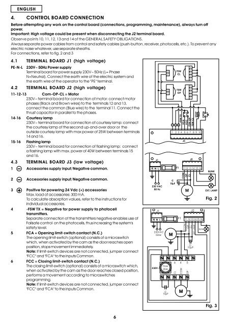
For connections, refer to fig. 2 and 3<br />
4.1 TERMINAL BOARD J1 (high voltage)<br />
PE-N-L 230V~ 50Hz Power supply<br />
Terminal <strong>board</strong> <strong>for</strong> power supply 230V~ 50Hz (L= Phase<br />
N=Neutral). Connect the earth wire of the electric system and<br />
the earth wire of the o<strong>per</strong>ator to the "PE" terminal.<br />
4.2 TERMINAL BOARD J2 (high voltage)<br />
11-12-13 Com-OP-CL = Motor<br />
230V~ terminal <strong>board</strong> <strong>for</strong> connection of motor: connect motor<br />
phases (Black and Brown wires) to the terminals 12 and 13,<br />
connect the common (Blue wire) to the terminal 11. Connect the<br />
thrust capacitor in parallel to the phases.<br />
14-16 Courtesy lamp<br />
230V~ terminal <strong>board</strong> <strong>for</strong> connection of courtesy lamp: connect<br />
the courtesy lamp of the second up-and-over door or the<br />
outside courtesy lamp with max power of 25W between terminals<br />
14 and 16.<br />
15-16 Flashing lamp<br />
230V~ terminal <strong>board</strong> <strong>for</strong> connection of flashing lamp: connect<br />
a flashing lamp with max. power of 40W between terminals 15<br />
and 16.<br />
4.3 TERMINAL BOARD J3 (low voltage)<br />
1 Accessories supply input/Negative common.<br />
2 Accessories supply input/Negative common.<br />
3 Positive <strong>for</strong> powering 24 Vdc (+) accessories<br />
Max. load of accessories: 300 mA.<br />
To calculate absorption values, refer to the instructions <strong>for</strong><br />
individual accessories.<br />
4 -FSW TX = Negative <strong>for</strong> power supply to photocell<br />
transmitters.<br />
Separate connection of the transmitters negative enables use of<br />
Failsafe <strong>control</strong> on the photocells, thus increasing the system's<br />
safety level.<br />
5 FCA = Opening limit-switch contact (N.C.)<br />
The opening limit-switch (optional) consists of a microswitch<br />
which, when activated by the cam as the door reaches open<br />
position, stops movement immediately.<br />
Note: If limit-switch devices are not connected, jum<strong>per</strong> connect<br />
"FCC" and "FCA" to the inputs Common.<br />
6 FCC = Closing limit-switch contact (N.C.)<br />
The closing limit-switch (optional) consists of a microswitch which,<br />
when activated by the cam as the door reaches closed position,<br />
<strong>per</strong><strong>for</strong>ms a movement according to microswitches<br />
programming.<br />
Note: If limit-switch devices are not connected, jum<strong>per</strong> connect<br />
"FCC" and "FCA" to the inputs Common.<br />
<br />
<br />
<br />
<br />
<br />
<br />
<br />
<br />
<br />
<br />
<br />
<br />
<br />
<br />
<br />
<br />
<br />
<br />
<br />
<br />
<br />
<br />
<br />
<br />
<br />
<br />
<br />
<br />
<br />
<br />
<br />
<br />
<br />
<br />
<br />
<br />
<br />
<br />
<br />
<br />
<br />
<br />
<br />
<br />
<br />
<br />
<br />
<br />
<br />
<br />
<br />
<br />
<br />
<br />
<br />
<br />
<br />
<br />
<br />
<br />
<br />
<br />
<br />
<br />
<br />
<br />
<br />
<br />
<br />
<br />
Fig. 2<br />
6<br />
Fig. 3