apparecchiatura elettronica per basculanti control board for ... - Faac
apparecchiatura elettronica per basculanti control board for ... - Faac
apparecchiatura elettronica per basculanti control board for ... - Faac

Create successful ePaper yourself
Turn your PDF publications into a flip-book with our unique Google optimized e-Paper software.
ENGLISH<br />
7 FSW OP = Opening safety devices contact (N.C.)<br />
Safety devices are all devices (photocells, sensitive edges,...) with N.C. contact, which, if there is an obstacle in<br />
the area they protect, o<strong>per</strong>ate to stop or reverse door opening movement.<br />
They have no effect during closing.<br />
If the opening safety devices are engaged with the door closed, they inhibit any Open pulse.<br />
To install several safety devices, connect the N.C. contacts in series.<br />
Note: If opening safety devices are not connected, jum<strong>per</strong> connect inputs "FSW OP" and "-FSW TX".<br />
8 FSW CL = Closing safety devices contact (N.C.)<br />
Safety devices are all devices (photocells, sensitive edges,...) with N.C. contact, which, if there is an obstacle in<br />
the area they protect, o<strong>per</strong>ate to reverse door closing movement.<br />
They have no effect at opening.<br />
If the closing safety devices are engaged with the door open, they inhibit any Open pulse.<br />
To install several safety devices, connect the N.C. contacts in series.<br />
Note: If closing safety devices are not connected, jum<strong>per</strong> connect inputs "FSW CL" and "-FSW TX".<br />
9 STOP = STOP Command (N.C.)<br />
This is any device (e.g. a push-button) which, by opening a contact, stops door movement.<br />
To install several stop devices, connect the N.C. contacts in series.<br />
Note: If Stop devices are not connected, jum<strong>per</strong> connect “STOP” to the inputs Common.<br />
10 OPEN = OPEN Command (N.O.)<br />
This is any device (a push-button, a detector,...) which, by closing a contact, supplies an opening (or closing)<br />
pulse to the door.<br />
To install several Open devices, connect N.O. contacts in parallel.<br />
4.4 CONNECTOR J4 (low voltage)<br />
Connector J4 is used <strong>for</strong> rapid connection of MINIDEC, DECODER cards and 5-Pin RP RECEIVERS.<br />
Install by fitting the auxiliary cards so that their components side faces the inside of the <strong>control</strong> <strong>board</strong>.<br />
Insert and remove the cards after cutting power.<br />
5. SIGNALLING LEDs<br />
An LD1 led on the <strong>control</strong> <strong>board</strong> signals the correct power suppy to the <strong>control</strong> <strong>board</strong>.<br />
LED LIGHTED = powered <strong>control</strong> unit LED OFF = unpowered <strong>control</strong> unit<br />
6. PROGRAMMING<br />
To program o<strong>per</strong>ation of the automated system, you have to set the microswitches DS1 on the <strong>control</strong> <strong>board</strong>.<br />
Descriptions and tables <strong>for</strong> different settings and type of function (fig. 4 and 5) are shown below.<br />
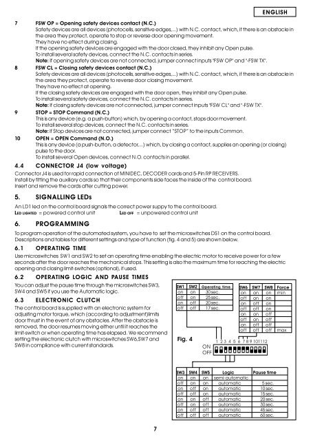
6.1 OPERATING TIME<br />
Use microswitches SW1 and SW2 to set an o<strong>per</strong>ating time enabling the electric motor to receive power <strong>for</strong> a few<br />
seconds after the door reaches the mechanical stops. This setting is also the maximum time <strong>for</strong> reaching the electric<br />
opening and closing limit-switches (optional), if used.<br />
6.2 OPERATING LOGIC AND PAUSE TIMES<br />
You can adjust the pause time through the microswitches SW3,<br />
SW4 and SW5 if you use the Automatic logic.<br />
6.3 ELECTRONIC CLUTCH<br />
The <strong>control</strong> <strong>board</strong> is supplied with an electronic system <strong>for</strong><br />
adjusting motor torque, which (according to adjustment)limits<br />
door thrust in the event of any obstacles. After the obstacle is<br />
removed, the door resumes moving either until it reaches the<br />
limit-switch or when o<strong>per</strong>ating time has elapsed. We recommend<br />
setting the electronic clutch with microswitches SW6,SW7 and<br />
SW8 in compliance with current standards.<br />
SW1 SW2 O<strong>per</strong>ating time<br />
on on 30 sec.<br />
off on 25 sec.<br />
on off 20 sec.<br />
off off 17 sec.<br />
Fig. 4<br />
<br />
<br />
SW6 SW7 SW8 Force<br />
on on on min<br />
off on on<br />
on off on<br />
off off on<br />
on on off<br />
off on off<br />
on off off<br />
off off off max<br />
<br />
SW3 SW4 SW5 Logic Pause time<br />
on on on semi-automatic<br />
off on on automatic 5 sec.<br />
on off on automatic 10 sec.<br />
off off on automatic 15 sec.<br />
on on off automatic 20 sec.<br />
off on off automatic 30 sec.<br />
on off off automatic 45 sec.<br />
off off off automatic 60 sec.<br />
7