Solarstation L - Meibes
Solarstation L - Meibes
Solarstation L - Meibes

You also want an ePaper? Increase the reach of your titles
YUMPU automatically turns print PDFs into web optimized ePapers that Google loves.
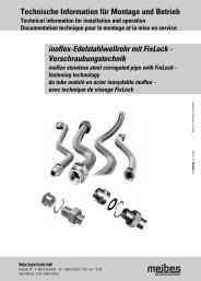
Technische Information für Montage und Betrieb<br />
Technical information for installation and operation<br />
Documentation technique pour le montage et la mise en service<br />
D<br />
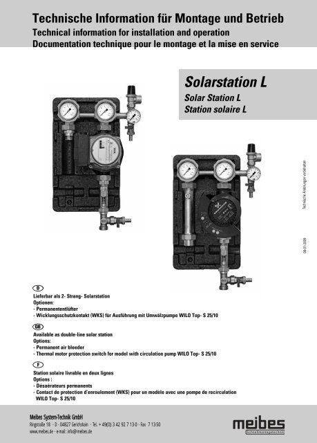
Lieferbar als 2- Strang- <strong>Solarstation</strong><br />
Optionen:<br />
- Permanententlüfter<br />
- Wicklungsschutzkontakt (WKS) für Ausführung mit Umwälzpumpe WILO Top- S 25/10<br />
GB<br />
Available as double-line solar station<br />
Options:<br />
- Permanent air bleeder<br />
- Thermal motor protection switch for model with circulation pump WILO Top- S 25/10<br />
F<br />
<strong>Meibes</strong> System-Technik GmbH<br />
Ringstraße 18 · D - 04827 Gerichshain · Tel. + 49(0) 3 42 92 7 13-0 · Fax 7 13-50<br />
www.meibes.de · e-mail: info@meibes.de<br />
<strong>Solarstation</strong> L<br />
Solar Station L<br />
Station solaire L<br />
Station solaire livrable en deux lignes<br />
Options :<br />
- Désaérateurs permanents<br />
- Contact de protection d’enroulement (WKS) pour un modèle avec une pompe de recirculation<br />
WILO Top- S 25/10<br />
Technische Änderungen vorbehalten<br />
08-01-2009
Inhalt<br />
Table of contents<br />
Table des matières<br />
D GB F<br />
Kapitel Titel Chapter Title Chapitre Titre Seite/ Page/ Page<br />
1 Sicherheitshinweise Safety notes Consignes de sécurité 2<br />
1.1 Vorschriften/Richtlinien Regulations/Guidelines Règlements/directives 2<br />
1.2 Bestimmungsgemäße Intended use Utilisation conforme aux<br />
Verwendung prescriptions 4<br />
1.3 Erstinbetriebnahme Initial start-up Première mise en service 5<br />
1.4 Arbeiten an der Anlage Working on the system Travaux sur l’installation 5<br />
1.5 Haftung Liability Responsabilité 6<br />
2. Technische Daten Technical Data Caractéristiques techniques 7<br />
3. Montage Installation Montage 10<br />
3.1 Wandmontage Wall-mounted installation Montage mural 10<br />
3.2 Absperrarmaturen Shut-off fittings Vannes d’arrêt 11<br />
3.3 Thermometerwechsel Changing thermometers Echange du thermomètre 13<br />
3.4 Sicherheitsventil Safety valve Soupape de sécurité 13<br />
3.5 Rückflussverhinderer Backflow preventer Clapet anti-retour 14<br />
3.6 Anschluss eines Connecting an expansion Raccordement d’un vase d’expansion<br />
Ausdehnungsgefäßes (bauseits) vessel (provided on site) (fourni par le client) 15<br />
3.7 Wärmeträgermedium Heat transfer medium Agent caloporteur 15<br />
4. Druckprobe, Befüllen und Pressure Test, Filling and Evacuation, remplissage et<br />
Spülen der Anlage Flushing the System purge de l’installation 16<br />
4.1 Spülen und Befüllen Flushing and filling Purge et remplissage 16<br />
4.2 Druckprobe Leak test Essai de pression 17<br />
4.3 Entlüften Venting Purge d’air 17<br />
4.4 Entleeren Draining Vidange 18<br />
5. Ausführungen Versions Déclarations 19<br />
1
1. Sicherheitshinweise<br />
Safety notes<br />
Consignes de sécurité<br />
D<br />
Lesen Sie vor der Montage diese Anleitung sorgfältig durch.<br />
Die Montage und Erstinbetriebnahme der Komplettstation<br />
darf nur von einer zugelassenen Fachfirma ausgeführt<br />
werden.<br />
Machen Sie sich vor Arbeitsbeginn mit allen Teilen und deren<br />
Handhabung vertraut.<br />
GB<br />
Read through these instructions carefully before installation.<br />
The complete station may be installed and initially started up<br />
by an approved, qualified firm only.<br />
Familiarise yourself with all the parts and their handling<br />
before starting the work.<br />
F<br />
Merci de lire attentivement le présent mode d’emploi avant le<br />
montage.<br />
Le montage et la première mise en service de la station<br />
intégrale doivent être effectués par une société spécialisée et<br />
agrée. Avant de commencer le travail, familiarisez-vous bien<br />
avec le fonctionnement de toutes les pièces.<br />
2<br />
- Vor Gebrauch Monteageanleitung lesen<br />
- Read the assembly instructions before use<br />
- Avant l'utilisation, lire les instructions de montage<br />
- Schnittgefahr<br />
- Risk of cutting<br />
- Risque de se couper<br />
- Quetschgefahr<br />
- Risk of crushing<br />
- Risque de se couper<br />
- Gefahr erhöhter Temperatur<br />
- Risk of increased temperature<br />
- Risque de haute température<br />
- Gefahr elektrischer Spannung<br />
- Risk of electrical voltage<br />
- Danger dû à la tension électrique<br />
- Sturzgefahr bei der Montage<br />
- Risk of dropping during assembly<br />
- Risque de tomber lors du montage<br />
1.1 Vorschriften/Richtlinien<br />
Regulations/Guidelines<br />
Règlements/directives<br />
D<br />
Beachten Sie die gültigen Unfallverhütungsvorschriften,<br />
Umweltvorschriften und gesetzlichen Regeln für die Montage,<br />
Installation und den Betrieb. Des weiteren die einschlägigen<br />
Richtlinien der DIN, EN, DVGW, VDI und VDE (inkl. Blitzschutz)<br />
sowie alle aktuellen relevanten länderspezifischen Normen,<br />
Gesetze und Richtlinien.<br />
Elektroanschluss:<br />
Elektrische Anschlussarbeiten dürfen nur durch qualifiziertes<br />
Elektrofachpersonal ausgeführt werden. Die VDE - Richtlinien<br />
und die Vorgaben, des zuständigen EVU sind einzuhalten.<br />
Auszug:<br />
Thermische Solaranlagen und ihre Bauteile:<br />
DIN EN 12975 Sonnenkollektoren<br />
DIN EN 12976 Vorgefertigte Anlagen<br />
DIN EN 12977 Kundenspezifisch gefertigte Anlagen<br />
Elektrischer Anschluss:<br />
VDE 0100: Errichtung elektrischer Betriebsmittel,<br />
Erdung, Schutzleiter, Potentialausgleichsleiter.<br />
VDE 0185: Allgemeines für das Errichten von<br />
Blitzschutzanlagen.<br />
VDE 0190: Hauptpotentialausgleich von<br />
elektrischen Anlagen.<br />
Zusätzliche Richtlinien und Hinweise:<br />
VDI 6002 Blatt 1 Allgemeine Grundlagen,<br />
Systemtechnik und Anwendung im<br />
Wohnungsbau<br />
VDI 6002 Blatt 2 Anwendungen in Studentenwohnheimen,<br />
Seniorenheimen,<br />
Krankenhäusern, Hallenbädern und<br />
auf Campingplätzen
1. Sicherheitshinweise<br />
Safety notes<br />
Consignes de sécurité<br />
GB<br />
Note and observe the accident prevention regulations/health<br />
& safety regulations, the environmental regulations and the<br />
statutory regulations for assembly, installation and operation.<br />
Furthermore, the relevant guidelines of the DIN, EN, DVGW,<br />
VDI and VDE (incl. lightning protection) as well as all relevant<br />
country-specific standards, laws and guidelines.<br />
Electrical connection:<br />
Electrical connection work may only be carried out by<br />
qualified electricians. The VDE guidelines and regulations of<br />
the electrical utility company responsible must all be<br />
complied with.<br />
Extract:<br />
Thermal solar systems and their components:<br />
DIN EN 12975 Solar collectors<br />
DIN EN 12976 Prefabricated systems<br />
DIN EN 12977 Custom built systems<br />
Electrical connection:<br />
VDE 0100: Construction of electrical equipment,<br />
earthing, protective conductors,<br />
equipotential conductors.<br />
VDE 0185: General information for the installation of<br />
lightning protection systems.<br />
VDE 0190: Main equipotential bonding of electrical<br />
systems.<br />
Additional guidelines and notes:<br />
VDI 6002 Part 1 General principles, systems engineering<br />
and use in housing<br />
VDI 6002 Part 2 Uses in student hostels, retirement<br />
homes, hospitals, indoor swimming pools<br />
and on camping sites<br />
F<br />
Respectez les règlements en vigueur relevant de la prévention<br />
des accidents, de la protection de l’environnement et les<br />
règlements législatifs concernant le montage, l’installation et<br />
le fonctionnement. Par ailleurs, respectez également les<br />
directives correspondantes et conformes aux normes DIN, EN,<br />
DVGW, VDI et VDE (protection contre la foudre inclue) ainsi<br />
que toutes les normes, lois et directives en vigueur dans<br />
haque pays.<br />
Raccordements électriques :<br />
Les travaux de raccordements électriques doivent être<br />
effectués uniquement par un électricien agrée. Les directives<br />
de l’Association de l’électrotechnique, de l’électronique et de<br />
la technique d’information (Verband der Elektrotechnik,<br />
Elektronik und Informationstechnik «VDE») et les prescriptions<br />
du distributeur d’énergie compétent sont à respecter.<br />
Extrait :<br />
Installations solaires thermiques et leurs éléments de<br />
construction :<br />
DIN EN 12975 Collecteurs de soleil<br />
DIN EN 12976 Installations préfabriquées<br />
DIN EN 12977 Installations fabriquées sur mesure<br />
Raccordements électriques :<br />
VDE 0100: mise en service de matériaux électriques,<br />
mise à la terre, conducteurs de protection,<br />
conducteurs d’équipotentialité.<br />
VDE 0185: généralités concernant la mise en service<br />
d’installations de protection contre<br />
la foudre.<br />
VDE 0190: conducteur principal d’équipotentialité<br />
sur des installations électriques.<br />
Consignes et directives supplémentaires :<br />
VDI 6002 Feuille 1 Généralités de base, génie des systèmes<br />
techniques et utilisation dans le bâtiment<br />
VDI 6002 Feuille 2 Utilisation dans les foyers d’étudiants,<br />
résidences pour personne du troisième<br />
âge, hôpitaux, piscines couvertes et<br />
campings.<br />
3
1. Sicherheitshinweise<br />
Safety notes<br />
Consignes de sécurité<br />
1.2 Bestimmungsgemäße Verwendung<br />
4<br />
Intended use<br />
Utilisation conforme aux prescriptions<br />
D F<br />
Die beschriebenen Stationen sind nur mit geeigneter und<br />
zugelassener Solarflüssigkeit zu betreiben. Es ist auf einen<br />
ausreichenden Frostschutzgehalt zu achten.<br />
Die Verwendung eines anderen Mediums ist nicht zulässig.<br />
Medientemperatur > 60 °C (Verbrühungsgefahr)<br />
Soll- bzw. Befülldruck < Ansprechdruck der<br />
Sicherheitsarmatur<br />
Alle Absperrarmaturen dürfen nur vom zugelassenen<br />
Fachmann im Servicefall und bei abgedeckten<br />
Kollektoren geschlossen werden, da ansonsten die<br />
Sicherheitsarmaturen ihre Wirkung verlieren.<br />
Nehmen Sie keine Veränderungen an den elektrischen<br />
Bauteilen, der Konstruktion oder den hydraulischen<br />
Komponenten vor! Sie beeinträchtigen sonst die sichere<br />
Funktion der Anlage.<br />
GB<br />
The described station is intended for primary operation of the<br />
solar substation with propylene glycol - water mixtures. Use<br />
of other media is not allowed.<br />
Media temperature > 60 °C (Risk of scalding)<br />
Setpoint and filling pressure < pickup pressure of the<br />
safety fitting<br />
All shut-off fittings may be closed in the service case<br />
only and only if the collectors are covered as otherwise<br />
the safety fittings lose their effect.<br />
Caution:<br />
Do not make any changes to electrical components, the design<br />
or the hydraulic components! Otherwise you will impair the<br />
safe function of the system.<br />
La station décrite est prévue pour le fonctionnement primaire<br />
de la station de transmission solaire avec un mélange à base<br />
de propylène glycol et eau. L’utilisation d’un autre agent n’est<br />
pas autorisée.<br />
Température de l’agent > 60 °C (danger d’échaudement)<br />
Pression de consigne ou < pression de démarrage de la<br />
de remplissage vanne de sécurité<br />
Les vannes d’arrêt ne doivent être fermées qu’en cas de<br />
nécessité et avec les capteurs recouverts, sinon elles<br />
perdraient de leur effet.<br />
Attention :<br />
N’effectuez aucune transformation des composants<br />
électriques, de la construction en elle-même ou des<br />
composants hydrauliques ! Sinon vous compromettez le bon<br />
fonctionnement de l’installation.
1. Sicherheitshinweise<br />
Safety notes<br />
Consignes de sécurité<br />
1.3 Erstinbetriebnahme<br />
Initial commissioning<br />
Première mise en service<br />
D<br />
Vor der Erstinbetriebnahme ist die Anlage auf Dichtheit, eine<br />
korrekte hydraulische Anbindung sowie sorgfältige und<br />
korrekte elektrische Anschlüsse zu prüfen. Des weiteren ist<br />
eine sorgfältiges bzw. bedarfsgerechtes Spülen gemäß<br />
DIN 4753 der Anlage durchzuführen. Die Erstinbetriebnahme<br />
hat durch eine geschulte Fachkraft zu erfolgen und ist schriftlich<br />
zu protokollieren. Darüber hinaus sind die Einstellwerten<br />
schriftlich festzuhalten.<br />
Die technische Dokumentation hat am Gerät zu verbleiben.<br />
GB<br />
Before the initial commissioning, the system must be checked<br />
for any leakage as well as to make sure the hydraulic linkage<br />
is correct and that the electrical connection work has been<br />
carried out with care and correctly. The system must also be<br />
carefully flushed in accordance with DIN 4753. The initial<br />
commissioning must be carried out by a trained specialist and<br />
a written record of it must be drawn up. In addition to this, the<br />
settings must also recorded in writing. The technical<br />
documentation must remain with equipment.<br />
F<br />
Avant la première mise en service, il faut vérifier l’étanchéité<br />
de l’installation, le bon branchement des raccords<br />
hydrauliques et un travail de raccordement électrique correct.<br />
De plus, il faut effectuer une purge minutieuse<br />
de l’installation conformément à la norme DIN 4753.<br />
La première mise en service doit être effectuée par du<br />
personnel formé et spécialisé et un compte-rendu doit être<br />
fait par écrit. Par ailleurs, les valeurs d’ajustement sont à<br />
noter. La documentation technique doit toujours se trouver à<br />
proximité de l’appareil.<br />
1.4 Arbeiten an der Anlage<br />
D<br />
Working on the system<br />
Travaux sur l’installation<br />
Die Anlage ist spannungsfrei zu schalten und auf<br />
Spannungsfreiheit zu kontrollieren (z.B. an der<br />
separaten Sicherung oder einem Hauptschalter).<br />
Anlage gegen Wiedereinschalten sichern.<br />
Die Kollektoren sind abzudecken, um das System abzukühlen.<br />
ACHTUNG: Verbrühungsgefahr:<br />
Medientemperatur > 60°C<br />
GB<br />
The system must be disconnected from the power supply and<br />
checked to ensure it is safely isolated from the power supply<br />
(e.g. at the separate fuse or a master switch).<br />
Secure the system against being switched back on again.<br />
IMPORTANT: Risk of scalding:<br />
Media temperature > 60°C<br />
F<br />
L’installation doit être mise hors tension, celle-ci devant être<br />
contrôlée (par exemple sur les fusibles séparés<br />
ou sur le commutateur principal). L’installation doit être<br />
protégée contre toute nouvelle mise en circuit.<br />
ATTENTION: Danger d’échaudement:<br />
Température de l’agent > 60°C<br />
5
1. Sicherheitshinweise<br />
Safety notes<br />
Consignes de sécurité<br />
1.5 Haftung<br />
Liability<br />
Responsabilité<br />
D<br />
Für diese Unterlage behalten wir uns alle Urheberrechte vor.<br />
Missbräuchliche Verwendung, insbesondere Vervielfältigung<br />
und Weitergabe an Dritte ist nicht gestattet.<br />
Diese Montage- und Bedienungsanleitung ist dem Kunden zu<br />
übergeben. Das ausführende bzw. zugelassene Gewerke (z.B.<br />
Installateur) hat dem Kunden die Wirkungsweise und<br />
Bedienung des Gerätes verständlich zu erklären.<br />
GB<br />
We reserve all copyrights to this document.<br />
These installation and operating instructions must be handed<br />
over to the customer. The skilled trades carrying out the work<br />
(e.g. fitter) must explain to the customer how the equipment<br />
works and how to operate it in a way they can understand.<br />
F<br />
Nous nous réservons les droits d’auteurs pour le présent<br />
document. Le mode d’emploi du montage et de l’utilisation<br />
doit être remis au client. Le personnel qualifié (par exemple<br />
l’installateur) doit instruire le client de manière<br />
compréhensive de l’utilisation correcte et des effets<br />
de l’appareil.<br />
6
2. Technische Daten<br />
Technical Data<br />
Caractéristiques techniques<br />
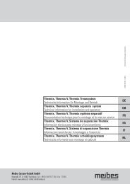
D<br />
Für den Einsatz in thermischen Solaranlagen bis ca. 50 m 2<br />
Kollektorfläche. (In Abhängigkeit von Typ und vorherrschenden/bestehenden<br />
Anlagenparametern)<br />
Die Solarübergabestation wird als 2- Strangausführung vormontiert<br />
geliefert. Ausdehnungsgefäße und Zubehör sind<br />
nicht im Lieferumfang enthalten und müssen den anlagentechnischen<br />
Erfordernissen montiert werden.<br />
1 Sicherheitsventil<br />
2 Anschluss für Ausdehnungsgefäß (verdeckt)<br />
3 Manometer<br />
4 KFE- Hahn mit Kappe und Schlauchtülle<br />
5 Umwälzpumpe<br />
6 Volumenstrombegrenzer<br />
7 KFE- Hahn mit Kappe und Schlauchtülle<br />
8 Absperrkugelhahn 1“IG x 1 1/2“IG-Überwurfmutter mit<br />
integrierter Schwerkraftbremse<br />
9 Absperrkugelhahn 1“IG x 1 1/2“IG-Überwurfmutter mit<br />
integrierter Schwerkraftbremse (handaufstellbar)<br />
10 Kugelhahngriff mit integriertem Thermometer<br />
11 Schnellentlüfter<br />
12 Permanententlüfter<br />
13 Blockisolierung<br />
GB<br />
For use in thermal solar collector systems with collector areas<br />
of up to approx 50 m 2 (Depending on model and<br />
prevailing/existing system parameters)<br />
The solar transfer station comes prefabricated with a doubleline<br />
design. It does not come with expansion tanks or<br />
accessories, which have to be installed to meet the system<br />
requirements.<br />
1 Safety valve<br />
2 Connection for expansion tank (concealed)<br />
3 Pressure gauge<br />
4 Ball valve for filling and draining with cap and hose<br />
connector<br />
5 Circulation pump<br />
6 Volume flow limiter<br />
7 Ball valve for filling and draining with cap and hose<br />
connector<br />
8 Shut-off ball valve 1" internal thread x 1 1/2" internalthread<br />
coupling nut with integrated gravity brake<br />
9 Shut-off ball valve 1" internal thread x 1 1/2" internalthread<br />
coupling nut with integrated gravity brake<br />
(manually positionable)<br />
10 Ball valve handle with integrated thermometer<br />
11 Quick air-bleeder<br />
12 Permanent air bleeder<br />
13 Block insulation<br />
F<br />
Pour une utilisation dans les installations solaires thermiques<br />
ayant une surface de récupération allant jusqu’à env. 50 m 2 .<br />
(Dépendant du type et des paramètres de l’installation<br />
prédominants/préexistants)<br />
La station de transmission solaire est livrée avec deux lignes<br />
en tant qu’unité prémontée. Les vases d’expansion et autres<br />
accessoires ne sont pas compris dans le volume de livraison<br />
et doivent être montés conformément aux exigences<br />
techniques de l’installation.<br />
1 Soupape de sécurité<br />
2 Raccordement pour un vase d’expansion (caché)<br />
3 Manomètre<br />
4 Robinet d’arrêt à boisseau sphérique avec capuchon et<br />
raccord d’extrémité<br />
5 Pompe de recirculation<br />
6 Limiteur de débit volumétrique<br />
7 Robinet d’arrêt à boisseau sphérique avec capuchon et<br />
raccord d’extrémité<br />
8 Robinet d’arrêt à boisseau sphérique 1“IG x 1 1/2“IGécrou-raccord<br />
avec frein à commande par gravité intégré<br />
9 Robinet d’arrêt à boisseau sphérique 1“IG x 1 1/2“IGraccord<br />
avec frein à commande par gravité intégré<br />
(réglable manuellement)<br />
10 Poignée du robinet d’arrêt à boisseau sphérique avec<br />
thermomètre intégré<br />
11 Désaérateurs rapides<br />
12 Désaérateurs permanents<br />
13 Bloc isolant<br />
7
2. Technische Daten<br />
Technical Data<br />
Caractéristiques techniques<br />
D<br />
Anschlüsse : Solarkreis : 1"IG<br />
Speicherkreis : 1“AG<br />
für Ausdehnungsgefäß : 3/4"AG<br />
max. zul. Temperatur : +110 °C, kurzzeitig +130 °C (max. zul. Temp. der Pumpe beachten!)<br />
max. zul. Druck : 6 bar (Ansprechdruck Sicherheitsventil beachten!)<br />
Rückflussverhinderer : 2-Strang: 2x 200 mmWs<br />
Volumenstromanzeiger : 10 ... 40 l/min<br />
Thermometer : Anzeigebereich 20 ... 150 °C<br />
Manometer : Anzeigebereich 0 ... 10 bar<br />
Sicherheitsventil : Ansprechdruck 6 bar<br />
Abmessungen gesamt : Höhe : 420 mm<br />
Breite : 250 mm<br />
Tiefe : 246 mm<br />
Achsabstand : 125 mm<br />
GB<br />
Connections : Solar circuit : 1"internal thread<br />
Storage tank circuit : 1“external thread<br />
for expansion vessel : 3/4"external thread<br />
Max. temperature allowed : +110 °C, short-term +130 °C (note max allowable temp of the pump!)<br />
Max. pressure allowed : 6 bar (note pick-up pressure of safety valve!)<br />
Backflow preventer : 2-branch: 2x 200 mmWs<br />
Volume flow indicator : 10 ... 40 l/min<br />
Thermometer : Display range 20 ... 150 °C<br />
Pressure gauge : Display range 0 ... 10 bar<br />
Safety valve : Pick-up pressure 6 bar<br />
Dimensions, overall : Height : 420 mm<br />
Width : 250 mm<br />
Depth : 246 mm<br />
Centre to centre spacing : 125 mm<br />
F<br />
Raccords : Circuit solaire : 1"IG<br />
Circuit du chauffage : 1“AG<br />
pour vase d’expansion : 3/4"AG<br />
Température max. admise : +110 °C, brièvement +130 °C (attention à la température max. admise de la pompe!)<br />
Pression max. admise : 6 bar (attention à la pression de démarrage de la soupape de sécurité!)<br />
Clapet anti-retour : 2-lignes: 2x 200 mmWs<br />
Indicateur de débit volumique : 10 ... 40 l/min<br />
Thermomètre : Plage d’affichage 20 ... 150 °C<br />
Manometer : Plage d’affichage 0 ... 10 bar<br />
Soupape de sécurité : Pression de démarrage 6 bar<br />
Dimensions totales : Hauteur : 420 mm<br />
Largeur : 250 mm<br />
Profondeur : 246 mm<br />
Entraxe : 125 mm<br />
8
2. Technische Daten<br />
Technical Data<br />
Caractéristiques techniques<br />
Pressure loss [bar]<br />
Perte de pression [bar]<br />
Volumetric flow - pressure loss diagram<br />
Single branch solar station Type S<br />
Volumetric flow [l/h]<br />
Débit volumique [l/h]<br />
Diagramme de débit volumique et de perte de pression<br />
Station solaire à 1 ligne, type S<br />
9
3. Montage<br />
Installation<br />
Montage<br />
3.1 Wandmontage<br />
Wall-mounted installation<br />
Montage mural<br />
D<br />
Die Montage hat an einer tragfähigen und trocknen Wand zu<br />
erfolgen. Der Abstand zu den Kollektoren ist so zu wählen,<br />
dass eine Überhitzung der Station und des<br />
Ausdehnungsgefäßes ausgeschlossen wird<br />
(gegebenenfalls Vorschaltgefäß einsetzen). Gefährdungen<br />
durch angrenzende Bauwerkskomponenten, Elektro-, Gas-,<br />
Wasser- oder Heizungsrohren sind zu vermeiden. Der freie<br />
Zugang zur Station, Sicherheitsarmaturen und den<br />
Anschlussleitungen ist sicherzustellen.<br />
1. Montageort wählen<br />
2. Bohrlöcher mittels Isolierungsunterschale ausrichten und<br />
markieren.<br />
3. Bohrlöcher erstellen und Dübel einschlagen<br />
4. Station mit Isolationsunterschale anschrauben<br />
5. Rohrnetzanbindung spannungsfrei herstellen<br />
GB<br />
The installation must be carried out on a dry wall able to<br />
accept the load. The distance to the collectors should be<br />
selected such that any overheating of the station and the<br />
expansion tank will be ruled out (use intermediate tank).<br />
Avoid any risks arising from adjacent building components,<br />
electrical conduits, gas pipes, water pipes or heating pipes.<br />
Ensure clear access to the station, safety fittings and<br />
connecting lines.<br />
1. Select location of assembly<br />
2. Align and mark spots for drill holes using bottom<br />
insulating panel.<br />
3. Drill holes and put in anchors.<br />
4. Screw station on with bottom insulating panel.<br />
5. Pipeline binding without tension manufacture<br />
10<br />
F<br />
Le montage doit être effectué sur un mur sec et résistant.<br />
L’écart jusqu’aux collecteurs est déterminé de façon à exclure<br />
une surchauffe de la station et du vase d’expansion (insérer<br />
un vase en amont). Empêcher tout danger lié aux composants<br />
d’ouvrage, aux tuyauteries de gaz, d’eau ou de chauffage.<br />
Assurer le libre accès à la station, aux robinetteries de<br />
sécurité et aux conduites de raccordement.<br />
1. Choisir le lieu de montage<br />
2. Placer et marquer les trous de perçage à l’aide du support<br />
de plateau isolant.<br />
3. Percer les trous et enfoncer les chevilles<br />
4. Fixer la station avec le support de plateau isolant<br />
5. Un lien de canalisation fabriquer sans tension
3. Montage<br />
Installation<br />
Montage<br />
3.2 Absperrarmaturen<br />
Shut-off fittings<br />
Vanne d’arrêt<br />
D<br />
Hinweis:<br />
Absperrarmaturen müssen stets geöffnet und gegen unbeabsichtigtes Schließen gesichert sein. Die Betätigung ist nur von<br />
geschulten Fachpersonal vorzunehmen! Für den Betrieb der Anlage müssen die Kugelhähne komplett geöffnet sein.<br />
Obere Absperrarmaturen<br />
Die Bedeutung der Stellung des Griffes entnehmen Sie bitte folgender Beschreibung:<br />
GB<br />
Note:<br />
The shut-off fittings always have to be open and secured against any accidental closing. It is only allowed for trained specialists<br />
to operate them. The ball valves have to be completely open for operation of the system.<br />
Upper shut-off fittings<br />
Find the meaning of the position of the handle in the following description:<br />
F<br />
Remarque :<br />
Les vannes d’arrêt doivent toujours être ouvertes et protégées contre toute fermeture intempestive. Seul le personnel formé et<br />
qualifié est autorisé à effectuer des manipulations sur la robinetterie! Les robinets à boisseau sphérique doivent être complètement<br />
ouverts lors de la mise en marche.<br />
Vanne d’arrêt supérieure<br />
Veuillez consultez la description suivante relative à la signification de l’emplacement de la poignée:<br />
geöffnet - Rückflussverhinderer aktiv<br />
open - backflow preventer actively<br />
ouvert - clapets anti-retour activement<br />
geöffnet - Rückflussverhinderer inaktiv<br />
open - backflow preventer inactively<br />
ouvert - clapets anti-retour nactif<br />
geschlossen / closed / fermé<br />
Nur auf der<br />
Vorlaufseite<br />
(vom Kollektor)!<br />
Only on the advance<br />
side (of the collector)!<br />
Seulement de côté<br />
d'avance<br />
(du collecteur)!<br />
D<br />
Die Betätigung der Kugelhähne ist nur von<br />
geschulten Fachpersonal vorzunehmen!<br />
GB<br />
It is only allowed for trained specialists to operate<br />
the ball valves!<br />
F<br />
Seul le personnel qualifié et formé est autorisé<br />
à effectuer des manipulations sur les<br />
robinets à boisseau sphérique!<br />
11
3. Montage<br />
Installation<br />
Montage<br />
D<br />
Unter Absperrarmatur<br />
Mit der Einstellschraube am Volumenstrombegrenzer kann der Volumenstrom gedrosselt bzw. der Durchgang geschlossen werden.<br />
Die Einstellschraube bitte nur mit einem geeigneten Schraubendreher betätigen. Die Absperrung arbeitet in der Stellung<br />
1 bis 2 (90° Drehung) als Volumenstrombegrenzer.<br />
GB<br />
Lower shut-off fittings<br />
Using the adjusting screw on the volume flow limiter, the volume flow can be throttled or the through-flow shut off. Only operate<br />
the adjusting screw with a suitable screwdriver. In a position from 1 to 2 (90° turn), the shut-off acts as a volume flow limiter.<br />
F<br />
Vanne d’arrêt inférieure<br />
Le débit volumétrique peut être réduit avec la vis de réglage sur le limiteur de débit volumétrique et l’entrée est fermée.<br />
Actionner la vis de réglage uniquement avec un tournevis adapté. Le blocage agit en position 1 jusqu’à 2 (pivotement à 90 °C)<br />
comme limiteur de débit volumétrique.<br />
12<br />
Position 1: geöffnet<br />
Position 1: open<br />
Position 1: ouvert<br />
Position 1: geschlossen<br />
Position 1: closed<br />
Position 1: fermé
3. Montage<br />
Installation<br />
Montage<br />
3.3 Thermometerwechsel<br />
Changing thermometers<br />
Echange du thermomètre<br />
D<br />
Die Thermometer sind nur eingesteckt und lassen sich einfach<br />
durch herausziehen tauschen. Es sollte beachtet werden, dass<br />
ein entnommenes Thermometer durch ein gleichartiges<br />
ersetzt wird. Bitte auf die farbliche Kennzeichnung achten.<br />
(rote Schrift = Vorlauf; blaue Schrift = Rücklauf)<br />
GB<br />
The thermometers are just inserted and can be replaced<br />
simply by pulling them out. Be sure to replace a thermometer<br />
taken out by one of the same type. Mind the colour<br />
identification.<br />
(Red lettering = forward flow; blue lettering = return<br />
flow)<br />
F<br />
Les thermomètres ne sont pas fixés et peuvent être échangés<br />
en les retirant. Il faut cependant tenir compte qu’un<br />
thermomètre retiré doit être remplacé uniquement par un<br />
thermomètre similaire. Veiller au marquage de couleur.<br />
(Écriture rouge = VL, écriture bleue = RL).<br />
3.4 Sicherheitsventil<br />
Safety valve<br />
Soupape de sécurité<br />
D<br />
Die Station ist mit einem Sicherheitsventil ausgestattet. Der<br />
Betriebsdruck kann an dem Manometer kontrolliert werden.<br />
Sicherheitsventile : 3/4“ x 1“<br />
Ansprechdruck primär : 6 bar<br />
Die mitgelieferte Sicherheitsbaugruppe an der dafür<br />
vorgesehenen Position der <strong>Solarstation</strong> fest montieren.<br />
GB<br />
The station is equipped with a safety valve. The operating<br />
pressure can be checked on the pressure gauge.<br />
Safety valves : 3/4" x 1"<br />
Primarily triggering pressure : 6 bar<br />
Firmly mount the safety subassembly that comes with the unit<br />
at solar station's position intended for it.<br />
F<br />
La station est équipée d’une soupape de sécurité. La pression<br />
en service peut être contrôlée au manomètre.<br />
Soupapes de sécurité : 3/4“ x 1“<br />
Pression de démarrage circuit primaire : 6 bars<br />
Monter le groupe de sécurité livré à la position prévue à cet<br />
effet sur la station solaire.<br />
Sicherheitsventil<br />
Safety valve<br />
Soupape de sécurité<br />
Manometer<br />
Pressure gauge<br />
Manometer<br />
13
3. Montage<br />
Installation<br />
Montage<br />
3.5 Rückflussverhinderer<br />
Backflow preventer<br />
Clapet anti-retour<br />
D<br />
Die Rückflussverhinderer in der Station verhindern bei<br />
Stillstand der Anlage ein unkontrolliertes Zirkulieren der<br />
Wärmeträgerflüssigkeit und wirken somit einer Auskühlung<br />
des Speichers entgegen. Diese befinden sich im Vor- und<br />
Rücklauf. Der Rückflussverhinderer im Vorlauf (vom Kollektor)<br />
kann durch Verstellen des Drehgriffes von der<br />
Anschlagsstellung um ca. 45° im Uhrzeigersinn kann dieser<br />
manuell geöffnet werden. Dieses ist vor allem beim Entleeren<br />
der Anlage zu beachten und anzuwenden.<br />
Öffnungsdruck: ca. 2x 200mm Wassersäule.<br />
0° - Kugelhahn VL offen, Rückflussverhinderer aktiv<br />
45° - Kugelhahn VL offen und Rückflussverhinderer inaktiv<br />
90° - Kugelhahn VL geschlossen<br />
GB<br />
The backflow preventer in the station prevent uncontrolled<br />
circulation of the medium when the system stops, thus<br />
counteracting any cooling down of the storage tank.<br />
These are located in the foreword flow and return flow.<br />
The non-return valve in the foreword flow (see Fig. 10) can be<br />
manually opened (see Fig. 8) by turning the handle to the right<br />
by approx 45° (see Fig. 9) from the end of position. Bear this<br />
in mind and use it especially when draining the system.<br />
Cracking pressure: approx 2 x 200 mm water column<br />
0° - Ball valve open, non-return valve in operation<br />
45° - Ball valve open backflow preventer inactively<br />
90° - Ball valve closed<br />
Absperrkugelhähne 1“IG x 1 1/2“IG-Überwurfmutter mit<br />
integrierter Schwerkraftbremse (handaufstellbar)<br />
Shut-off ball valves 1" internal thread x 1 1/2" internalthread<br />
coupling nut with integrated gravity brake<br />
(manually positionable)<br />
Robinet d’arrêt à boisseau sphérique 1“IG x 1 1/2“IGécrou-raccord<br />
avec frein à commande par gravité<br />
intégré (réglable manuellement)<br />
14<br />
F<br />
Les clapets anti-retour sur la station empêchent lors de l’arrêt<br />
de l’installation une circulation incontrôlée du fluide et le<br />
refroidissement de l’accumulateur.<br />
Ceux-ci se situent au départ et au retour.<br />
Le clapet anti-retour situé au départ (voir figure 10) peut être<br />
ouvert manuellement par déplacement de la poignée<br />
pivotante à env. 45 ! (voir figure 9) en partant de la position<br />
de butée vers la droite (voir figure 8). Ceci est à observer et á<br />
appliquer surtout lors de la vidange de l’installation.<br />
Pression d’ouverture : env. 2x 200 mm colonne d’eau.<br />
0° - Robinet ouvert, clapet anti-retour en fonctionnement<br />
45° - Robinet ouvert ouvert clapet anti-retour nactif<br />
90° - Robinet fermé<br />
45 °C 0 °C 90 °C
3. Montage<br />
Installation<br />
Montage<br />
3.6 Anschluss eines<br />
Ausdehnungsgefäßes (bauseits)<br />
Connecting an expansion vessel (provided on site)<br />
Raccordement d’un vase d’expansion<br />
(fourni par le client)<br />
D<br />
Ausdehnungsgefäße nehmen die Volumenänderungen beim<br />
Aufheizen oder Abkühlen der Wärmeträgerflüssigkeit auf und<br />
halten eine Flüssigkeitsreserve zum Ausgleich einer geringen<br />
Leckagerate vor.<br />
Es sind nur geeignete und sachgemäß ausgelegte<br />
Ausdehnungsgefäße (vgl. DIN 4807) zu verwenden.<br />
Bei entsprechend vorherrschenden Temperaturen evtl.<br />
Vorschaltgefäße verwenden.<br />
GB<br />
Expansion tanks assume the changes in volume when lead<br />
liquid heats up or cools down and keep a reserve of liquid<br />
available to compensate a low leakage unit.<br />
Only use suitable and properly designed expansion<br />
tanks (cf DIN 4807). Use intermediate tanks if necessary,<br />
depending on the prevailing temperatures.<br />
F<br />
Les vases d’expansion captent les changements de volumes<br />
lors de l’échauffement ou du refroidissement du liquide et<br />
conservent une réserve de liquide pour compenser de petites<br />
fuites potentielles.<br />
Utiliser uniquement des vases d’expansion appropriés<br />
et montés correctement (voir DIN 4807).<br />
Utiliser éventuellement des vases insérés en amont en<br />
fonction des températures prédominantes.<br />
3.7 Wärmeträgermedium<br />
D<br />
Heat transfer medium<br />
Agent caloporteur<br />
Verwenden Sie nur geeignete und zugelassene<br />
Solarflüssigkeiten mit Frostschutzmittel (vgl. DIN 4757),<br />
die für Solaranlagen geeignet sind! Notieren Sie sich<br />
Hersteller und Typ, da diese unter Umständen nicht mit<br />
Mitteln anderer Hersteller gemischt werden dürfen.<br />
GB<br />
Only use solar liquid with an antifreeze agent that is<br />
suited or solar collector systems! Make a note of the<br />
manufacturer and type, as under some<br />
circumstances it is not allowed to mix agents from<br />
different manufacturers.<br />
F<br />
Utiliser uniquement de l’eau saline avec un produit<br />
antigel convenant aux installations solaires! Notez le<br />
type et le fabricant, car dans certains cas, le mélange<br />
mentionné ne devra pas être combiné avec les produits<br />
d’autres fabricants.<br />
15
4. Druckprobe, Befüllen und Spülen der Anlage<br />
Pressure Test, Filling and Flushing the System<br />
Essai de pression, de remplissage et purge de l’installation<br />
D<br />
Die folgenden Arbeiten dürfen nur durch geschultes<br />
Fachpersonal ausgeführt werden.<br />
Beim Abdrücken, Füllen und Spülen der Anlage ist darauf zu<br />
achten, dass alle Absperrarmaturen geöffnet sind. Die<br />
Kollektoren müssen abgekühlt sein und abgedeckt werden,<br />
um Verletzungen bzw. Beschädigungen vorzubeugen! An<br />
strahlungsintensiven Tagen sollte das Befüllen in den Morgenoder<br />
Abendstunden erfolgen. Keine Schaltvorgänge zur<br />
Druckentlastung mit dem Absperrarmaturen vornehmen.<br />
GB<br />
The following work may only be carried out by trained<br />
qualified personnel.<br />
When pressure-testing, filling and flushing the system, be<br />
sure that all the shut-off fittings are opened. The collectors<br />
have to be covered. Do not do any switching operations to<br />
relieve pressure with the shut-off fittings.<br />
F<br />
Les travaux suivants doivent être effectués uniquement<br />
par du personnel qualifié.<br />
Lors de l’évacuation, du remplissage et de la purge de l’installation,<br />
il faut veiller à ce que toutes les vannes d’arrêt soient<br />
ouvertes. Les collecteurs doivent être recouverts.<br />
Ne pas effectuer de changements de rapport pour la détente<br />
de la pression sur les dispositifs dotés de vannes d’arrêt.<br />
4.1 Spülen und Befüllen<br />
Flushing and filling<br />
Purge et remplissage<br />
D<br />
Ein sorgfältiges bzw. bedarfsgerechtes Spülen der Anlage ist<br />
durchzuführen. Es müssen vor Inbetriebnahme alle Schmutzund<br />
Luftpartikel aus der Anlage entfernt werden.<br />
Wird Wasser zum Spülen verwendet, ist die Anlage bei<br />
möglicher Frostgefahr am Aufstellungsort komplett zu<br />
Entleeren und sofort mit geeigneter und zugelassener<br />
Solarflüssigkeit mit Frostschutzmittel zu ersetzen.<br />
Es ist zu beachten, dass die untere Absperrung am<br />
Volumenstrommesser beim Befüllen geschlossen<br />
sein muss und der Kugelhahngriff im Vorlauf (vom Kollektor)<br />
auf 45 °C gestellt wird (vgl. Abb.). In dieser Position wird der<br />
Rückflussverhinderer geöffnet. Die Kollektoren müssen abgekühlt<br />
sein und abgedeckt werden, um Verletzungen bzw.<br />
Beschädigungen vorzubeugen! An strahlungsintensiven Tagen<br />
sollte das Befüllen in den Morgen- oder Abendstunden<br />
erfolgen.<br />
16<br />
GB<br />
Carry out a flush of the system suited for the requirements,<br />
doing so in accordance with DIN 4753. Before commissioning,<br />
all particles of soiling and air have to be removed from the<br />
system. If water is used for flushing, if there is a danger of<br />
freezing, the system must be completely drained or<br />
immediately replaced with antifreeze agent. Bear in mind that<br />
the lower shut-off on the volume flow meter has to be closed<br />
during filling, and the ball valve handle in the forward flow<br />
set to 45° C. This position will result in the non-return valve<br />
being opened. The collectors have to be covered to prevent<br />
injuries and/or damage.<br />
F<br />
Effectuer la purge de l’installation conformément à la norme<br />
DIN 4753. Avant la mise en service, toutes les particules d’air<br />
et d’impureté doivent être éliminées de l’installation. En cas<br />
de gel et si l’on utilise de l’eau pour le rinçage, il faut entièrement<br />
vider l’installation ou la remplir aussitôt d’antigel.<br />
Il faut veiller à ce que la vanne d’arrêt inférieure sur<br />
l’indicateur de débit volumétrique lors du remplissage dit être<br />
fermé et la poignée du robinet doit être réglée au départ<br />
à 45 °C. Le clapet anti-retour est ouvert par cette position.<br />
Les collecteurs doivent être recouverts afin d’éviter les<br />
blessures et les détériorations !<br />
geschlossen / closed / fermé<br />
Nach Beendigung die untere Absperrung öffnen und den<br />
Vorlaufgriff 45°C im Gegenuhrzeigersinn zurückstellen!<br />
When finished, open the lower shut-off and reset the forward<br />
flow handle to 45° C.<br />
Après l’arrêt, ouvrir la vanne d’arrêt inférieur et remettre la<br />
poignée de départ à 45 °!
4. Druckprobe, Befüllen und Spülen der Anlage<br />
Pressure Test, Filling and Flushing the System<br />
Essai de pression, de remplissage et purge de l’installation<br />
4.2 Druckprobe<br />
Leak test<br />
Essai de pression<br />
D<br />
Anschlüsse, Bauteile und Verbindungen auf Dichtheit<br />
kontrollieren. Bei Undichtheiten Anlage entleeren, nachbessern<br />
und Druckprobe wiederholen.<br />
GB<br />
Check the connections, components and connections for<br />
leaks. If there are any leaks, drain and repair the system and<br />
repeat the leak test.<br />
F<br />
Vérifier l’étanchéité des branchements, composants et<br />
raccordements. En cas de fuites, vider l’installation, effectuer<br />
les réparations et recommencer l’essai de pression.<br />
4.3 Entlüften<br />
Venting<br />
Purge d’air<br />
D<br />
Unsachgemäßes Entlüften führt zu Druckabfall und kann zu<br />
Störungen in der Solaranlage führen. Die Temperaturen der<br />
ausweichenden Luft und des Wärmeträgermediums können<br />
größer 60 °C sein, damit besteht erhöhte Verbrühungsgefahr.<br />
Der Entlüfter befindet sich am höchsten Punkt der Anlage.<br />
Nach dem Entlüften ist der Anlagendruck jeweils wieder auf<br />
den Betriebsdruck zu erhöhen!<br />
Im Betriebszustand am Permanententlüfter (Option)<br />
gelegentlich entlüften.<br />
GB<br />
Improper deaerating will result in a drop in pressure and can<br />
result in malfunctions in the solar collector system.<br />
The temperatures of the escaping air and heat transfer<br />
medium can be higher than 60 °C, making for a great danger<br />
of scalding. The air bleeder is situated at the highest point of<br />
the system. After each instance of deaerating, increase the<br />
system pressure back to the operating pressure.<br />
Occasionally deaerate in the operating state, using the<br />
permanent air bleeder (option).<br />
F<br />
Une purge d’air incorrecte entraîne une chute de pression et<br />
peut provoquer des perturbations de l’installation solaire.<br />
Les températures de l’air sortant et de l’agent caloporteur<br />
peuvent atteindre plus de 60 °C, ce qui présente un danger<br />
élevé d’échaudement.<br />
Le dispositif de désaération est situé au point culminant de<br />
l’installation. Après la purge d’air, il faut de nouveau<br />
augmenter la pression de l’installation au niveau de la pression<br />
de service !<br />
En état de marche, purger de temps en temps le désaérateur<br />
permanent (en option).<br />
17
4. Druckprobe, Befüllen und Spülen der Anlage<br />
Pressure Test, Filling and Flushing the System<br />
Essai de pression, de remplissage et purge de l’installation<br />
4.4 Entleeren<br />
Draining<br />
Vidange<br />
D<br />
Beim Entleeren der Anlage muss beachtet werden, dass der<br />
Griff des Vorlauf-Kugelhahnes auf 45 °C gestellt wird, bevor<br />
die Vorlaufseite am tiefsten Punkt entleert wird. In dieser<br />
Stellung ist der Rückflussverhinderer geöffnet.<br />
Die Rücklaufseite muß zum einem am tiefsten Punkt des<br />
Rohrkreislaufes und zum anderen am KFE-Hahn des<br />
Sicherheitssets entleert werden. Bei der Verwendung von<br />
Wasser, ist auf vollständige Entleerung des<br />
Rohrleitungssystems zu achten.<br />
Die Wärmeträgerflüssigkeit sollte mit einem geeignetem<br />
Auffangbehälter aufgefangen werden und wenn nötig<br />
umweltgerecht entsorgt werden.<br />
Hinweis: Anlage steht i.d.R. unter Druck! Verbrühungsgefahr!<br />
GB<br />
When draining the system, be sure the handle of the forward<br />
flow ball valve is set to 45° C before the forward flow side is<br />
drained at the lowest point. In this position, the non-return<br />
valve is open. The return flow side has to be drained both at<br />
the lowest point in the pipework circulation system and at the<br />
safety set's ball valve for filling and draining.<br />
When water is used, be sure the pipeline system is completely<br />
drained.<br />
The media and should be collected in a suitable container<br />
and, if necessary, disposed of in an environmentally conscious<br />
manner.<br />
Note: The system is usually under pressure.<br />
Danger of scalding!<br />
18<br />
F<br />
Lors de la vidange de l’installation, il faut veiller à ce que la<br />
poignée du robinet de départ soit réglé à 45 °C avant que la<br />
partie de départ soit vidangée au plus bas niveau. Dans cette<br />
position, le clapet anti-retour est ouvert. Le côté retour doit<br />
être vidangé à son niveau le plus bas du circuit de tuyauterie<br />
et d’autre part sur le robinet vidange-remplissage du dispositif<br />
de sécurité. En cas d’utilisation d’eau, il faut veiller à une<br />
vidange complète du système de tuyauterie.<br />
Il est conseillé de recueillir le fluide caloporteur dans un<br />
réservoir collecteur adapté et de l’éliminer écologiquement.<br />
Remarque : l’installation est en règle générale sous pression!<br />
Danger d’échaudement!
5. Ausführungen<br />
Versions<br />
Déclarations<br />
Die Preise entnehmen sie bitte der aktuellen Preisliste.<br />
Ausführung: Art.-Nr.<br />
<strong>Solarstation</strong> L mit<br />
Durchflussmengenanzeiger 10-40 l/min.<br />
ohne Pumpe 45704.100 EA<br />
mit Grundfos-Pumpe Solar 25-120 45704.120<br />
mit Wilo-Pumpe Top-S 25/10 45704.100 WI<br />
mit Wilo-Pumpe Stratos Para 25/1-11 A 45704.120 WI<br />
Wie zuvor, jedoch mit im Vorlauf montiertem Permanententlüfter für die stetige<br />
Abscheidung von Luft<br />
Durchflussmengenanzeiger 10-40 l/min.<br />
ohne Pumpe 45722.100 EA<br />
mit Grundfos-Pumpe Solar 25-120 45722.120<br />
mit Wilo-Pumpe Stratos Para 25/1-11 A 45722.120 WI<br />
Die Einbau- und Montagehinweise der Pumpenhersteller sind zu beachten.<br />
19
5. Ausführungen<br />
Versions<br />
Déclarations<br />
Zubehör:<br />
Solarregler<br />
Bezeichnung: Art.-Nr.<br />
BASIC:<br />
Digitaler Temperaturdifferenzregler für thermische Solaranlagen (1 Kollektorfeld, 1 Speicher):<br />
große multifunktionale LCD-Anzeige mit Piktogrammen, zentrale Tastenbedienung, 3 Eingänge<br />
für PT 1000 Fühler, 1 elektronischer Ausgang 230 VAC, Drehzahlregelung, Fehlerüberwachung,<br />
Handbetriebsmöglichkeit, Kollektorschutzfunktion, Rückkühlfunktion;<br />
inkl. 2 Universaltemperaturfühler PT 1000, Fühler = 6 mm, Länge= 45 mm, Kabellänge 2,5 m.<br />
20<br />
45111.5<br />
ENERGY:<br />
wie Solarregler BASIC, jedoch mit Röhrenkollektor- und Nachheizfunktion sowie Möglichkeit der<br />
Ertragsmessung in Kombination mit passendem Durchflußgeber (Option).<br />
45111.7<br />
MAXIMAL<br />
Universalregler für Solaranlagen mit bis zu 2 Kollektorfeldern und 2 Speichern;<br />
4 Relaisausgänge (elektronische Relais); Niederspannungsrelais für Nachheizung;<br />
8 Messeingänge für Temperatur, Volumenstrommesser und Solarsensor; Einfache Bedienung;<br />
Großes übersichtliches Display mit Hintergrundbeleuchtung<br />
Funktionen: Temperatur-Differenzregelung; Drehzahlregelung der Pumpen;<br />
Niederspannungsrelais für Nachheizfunktion; Speicher- und Kollektor- Sicherheitsfunktion;<br />
Heizungsunterstützung; Parallelladung der Speicher; Speichervorrang mit Pendelladung;<br />
Low-Flow-Funktion für Schichtenspeicher; eBus für Visualisierung und Datenlogger<br />
Weitere Funktionen: Ansteuerung eines externen Wärmetauschers; Ansteuerung eines<br />
externen Bypasses; Freie Zuordnung der Fühler mit 1 oder 2 Speicherfühlern;<br />
Zweiter Kollektorfühler für Ost- / Südausrichtung; Thermostat- und Temperaturvergleichsfunktion;<br />
Solarertrag; Kollektorüberwachung; Frostschutzfunktion; Antilegionellen-Funktion; Pumpen-<br />
Blockierschutz<br />
45111.9<br />
Durchflußgeber für Solarregler ENERGY / MAXIMAL (Option)<br />
Einbaulänge 110 mm, Anschlußgewinde 3/4"AG, Betriebstemperatur max. +90 °C,<br />
Nenndurchfluß Qn 1,5 ,Impulsfolge 1 Impuls/Liter,inkl. 1 Temperaturfühler PT1000<br />
Andere Typen auf Anfrage<br />
45111.72
5. Ausführungen<br />
Versions<br />
Déclarations<br />
Please refer to the current price list for prices.<br />
Type: Product No.<br />
<strong>Solarstation</strong> L mit<br />
volume flow indicator 10-40 l/min.<br />
ohne Pumpe 45704.100 EA<br />
mit Grundfos-Pumpe Solar 25-120 45704.120<br />
mit Wilo-Pumpe Top-S 25/10 45704.100 WI<br />
mit Wilo-Pumpe Stratos Para 25/1-11 A 45704.120 WI<br />
As above, however with permanent vent installed in the flow pipe for constant separation of air<br />
volume flow indicator 10-40 l/min.<br />
ohne Pumpe 45722.100 EA<br />
mit Grundfos-Pumpe Solar 25-120 45722.120<br />
mit Wilo-Pumpe Stratos Para 25/1-11 A 45722.120 WI<br />
The pump manufacturers' installation and assembly instructions must be noted and observed.<br />
21
5. Ausführungen<br />
Versions<br />
Déclarations<br />
Accessories:<br />
Solar controllers<br />
Name: Product No.<br />
BASIC:<br />
Digital differential thermostat for thermal solar systems (1 collector panel, 1 accumulator):<br />
Large multifunctional LCD display with pictograms, central key controls, 3 inputs for PT 1000<br />
sensors, 1 electronic output 230 VAC, speed control, error monitoring, manual mode option, collector<br />
protection function, recooling function; incl. 2 universal temperature sensors PT 1000,<br />
sensor = 6 mm, length = 45 mm, cable length 2.5 m.<br />
22<br />
45111.5<br />
ENERGY:<br />
as BASIC solar controller, however with tube collector and auxiliary heating function as well as<br />
option for measuring the yield in combination with suitable flow sensor (optional).<br />
45111.7<br />
MAXIMAL<br />
Universal controller for solar systems with up to 2 collector panels and 2 accumulators;<br />
4 relay outputs (electronic relay); Low voltage relay for auxiliary heating;<br />
8 measurement inputs for temperature, volumetric flowmeter and solar sensor;<br />
Easy to use; Large, clear display with background lighting, functions:<br />
differential temperature control; pump speed control; low voltage relay for auxiliary heating<br />
function; accumulator and collector safety function; heating support, parallel charging of the<br />
accumulators; storage priority with floating charge; Low-flow function for layered storage;<br />
eBus for visualisation and data logger<br />
Further functions:<br />
control of an external heat exchanger; control of an external heat bypass;<br />
free allocation of the sensors with 1 or 2 storage sensors; second collector sensor for east /<br />
south orientation; thermostat and temperature comparison function; solar yield;<br />
collector monitoring; anti-freeze function; anti-legionella function; pump anti-blocking device<br />
45111.9<br />
Flow sensor for ENERGY / MAXIMAL solar controllers (optional)<br />
Installed length 110 mm, connection thread 3/4" AG (outer thread), operating temperature<br />
max +90 °C, Nominal flow rate Qn 1.5, pulse sequence 1 pulse/litre, incl. 1 temperature sensor<br />
PT1000<br />
Other types available on request<br />
45111.72
5. Ausführungen<br />
Versions<br />
Déclarations<br />
Merci de consulter la liste des prix pour prendre connaissance de nos nouveaux tarifs.<br />
Modèle: Réf.<br />
<strong>Solarstation</strong> L mit<br />
Indicateur de débit volumique 10-40 l/min.<br />
ohne Pumpe 45704.100 EA<br />
mit Grundfos-Pumpe Solar 25-120 45704.120<br />
mit Wilo-Pumpe Top-S 25/10 45704.100 WI<br />
mit Wilo-Pumpe Stratos Para 25/1-11 A 45704.120 WI<br />
Identique au modèle précédent, sauf qu’un purgeur d’air est intégré dans le départ circuit pour une<br />
séparation continue de l’air.<br />
Indicateur de débit volumique 10-40 l/min.<br />
ohne Pumpe 45722.100 EA<br />
mit Grundfos-Pumpe Solar 25-120 45722.120<br />
mit Wilo-Pumpe Stratos Para 25/1-11 A 45722.120 WI<br />
Respecter les consignes d’installation et de montage du fabricant de pompes.<br />
23
5. Ausführungen<br />
Versions<br />
Déclarations<br />
Accessoires:<br />
Régulateur solaire<br />
Désignation: Réf.<br />
BASIC:<br />
Régulateur différentiel numérique de températures pour installations solaires thermiques (1<br />
champ de collecteurs, 1 réservoir): grand affichage multifonctionnel à cristaux liquides avec<br />
pictogrammes, commande centrale des touches, 3 entrées pour capteur PT 1000, 1 sortie<br />
électronique 230 VAC, régulateur de vitesses, surveillance des erreurs, possibilité de passer en<br />
mode de commande manuelle, fonction protection des collecteurs, fonction réfrigération de<br />
retour ; avec<br />
2 capteurs universels de température PT 1000, capteur = 6 mm, longueur = 45 mm, longueur<br />
de câble 2,5 m.<br />
24<br />
45111.5<br />
ENERGY:<br />
identique au régulateur solaire BASIC, mais doté d’un collecteur à tubes et d’une fonction de<br />
post-chauffage, également possibilité de mesurer le rendement en association avec un<br />
débitmètre adapté (optionnel).<br />
45111.7<br />
MAXIMAL<br />
Régulateur universel pour installations solaires avec jusqu’à 2 champs de collecteurs et<br />
2 réservoirs; 4 sorties de relais (relais électroniques); relais de basse tension pour un<br />
post-chauffage; 8 entrées de mesure pour la température, indicateur de débit et capteur solaire,<br />
commande simple; grand écran d’affichage bien dégagé au niveau de la vue avec éclairage de<br />
fond. Fonctions : régulateur différentiel de températures; régulateur de vitesse des pompes;<br />
relais de basse tensions avec fonction de post-chauffage; fonction de sécurité au niveau du<br />
réservoir et du collecteur; aide au chauffage ; charge parallèle des réservoirs ; stockage avec<br />
charge pendulaire; fonction Low-Flow (NdT : débit faible) pour chauffage à stratifications; eBus<br />
pour la visualisation et logger de données.<br />
Autres fonctions : activation d’un échangeur thermique externe; activation d’un by-pass externe;<br />
libre attribution des capteurs avec 1 ou 2 capteurs de réservoir; second capteur de collecteur<br />
pour orientation est / sud ; fonction de comparaison du thermostat et de la température;<br />
rendement solaire; contrôle des collecteurs; fonction : protection antigel;<br />
fonction anti-légionelles; fonction antiblocage des pompes.<br />
45111.9<br />
Débitmètre pour régulateur solaire ENERGY / MAXIMAL (optionnel)<br />
Longueur de montage 110 mm, raccord 3/4"AG, température de service max. : + 90 °C,<br />
débit nominal : Qn 1,5. Suite d’impulsions : 1 impulsion/litre, avec 1 capteur de température 1<br />
PT1000<br />
Autres modèles sur demande<br />
45111.72