5.Control system - Meibes
5.Control system - Meibes
5.Control system - Meibes

Create successful ePaper yourself
Turn your PDF publications into a flip-book with our unique Google optimized e-Paper software.
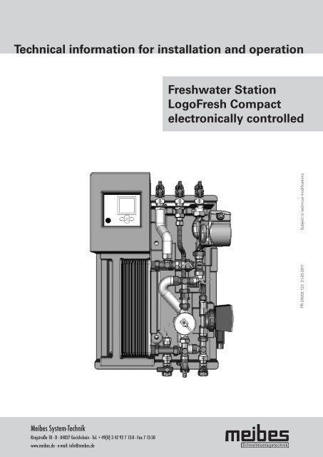
Technical information for installation and operation<br />
<strong>Meibes</strong> System-Technik<br />
Ringstraße 18 - D - 04827 Gerichshain - Tel. + 49(0) 3 42 92 7 13-0 - Fax 7 13-50<br />
www.meibes.de - e-mail: info@meibes.de<br />
Freshwater Station<br />
LogoFresh Compact<br />
electronically controlled<br />
PR 24002.123 31-03-2011 Subject to technical modifications
Contents<br />
Chapter Title Page<br />
1. Safety instructions 2<br />
2. Technical specifications 2<br />
2.1 Performance characteristics 3<br />
3. Equipment and functional description 4<br />
4. Installation 5<br />
4.1 Hydraulic connections 5<br />
4.2 Electrical connections 5<br />
5. Control <strong>system</strong> 6<br />
5.1 Display description 6<br />
5.2 Operating keys – description 6<br />
5.3 Control menu structure 7<br />
5.3.1 Explanation of menu items 8<br />
5.3.2 Information menu 8<br />
5.3.3 Programming menu 8<br />
5.3.4 Manual operation menu 9<br />
5.3.5 Basic setting menu 9<br />
6. Initial operation and <strong>system</strong> calibration 11<br />
6.1 Flushing and filling the <strong>system</strong> 11<br />
6.2 Controller calibration 11<br />
6.3 Calibration procedure 11<br />
6.3.1 Selecting pump capacity 11<br />
6.3.2 Characteristic curve calibration 11<br />
6.3.3 Circulation adjustment 12<br />
6.3.4 Detailed description of characteristic curve calibration 13<br />
7. System examples of controller settings 14<br />
7.1 Freshwater station with circulation in a time slot and 14<br />
with tapping detection<br />
7.2 Freshwater station with circulation only via 14<br />
tapping detection<br />
7.3 Freshwater station without circulation 14<br />
7.4 Freshwater station with reheating and/or activation 15<br />
7.5 Increasing the domestic hot water set temperature 15<br />
7.6 Freshwater stations as cascade connection 16<br />
7.6.1 Initial operation and <strong>system</strong> calibration of freshwater 16<br />
cascade<br />
7.7 Disinfecting the hot water and circulation pipes 17<br />
8. Releasing operating level for specialist tradesmen 17<br />
9. Trouble-shooting 18<br />
10. Factory setting and personal setting 19<br />
11. Diagrams 20<br />
1
1. Safety instructions<br />
■ The installation and initial operation of the freshwater<br />
station is only to be carried out by a specialist<br />
tradesman.<br />
■ The necessary DIN and VDE provisions are to be<br />
observed (e.g. DIN 4751, DIN 4753, DIN 1988<br />
and VDE 0100)<br />
■ The provisions of local energy supply companies are<br />
to be observed<br />
■ Improper installation as well as misuse of the<br />
freshwater station will exclude any liability as regards<br />
guarantee claims<br />
Please note:<br />
■ Before operating on the control <strong>system</strong> and the<br />
circulating pump, they are to be switched at zero<br />
potential as prescribed<br />
■ In the event of a power supply interruption, the<br />
preset values are retained<br />
■ In the event of a power failure, the <strong>system</strong> clock<br />
settings in the control <strong>system</strong> are retained for<br />
approx. 24 hours<br />
2. Technical specifications<br />
Heating connections 3/4“ female 3/4“ IG<br />
Plumbing connections 3/4” female 3/4” IG<br />
Heating operating pressure 3 bar<br />
Plumbing operating pressure 6 bar<br />
Maximum allowed temperature 110°C<br />
Controller protection class IP 54<br />
Supply voltage 230VAC / 50Hz<br />
Dimensions (height/length/breadth) in mm 660 x 455 x 215<br />
2<br />
■ A menu for basic settings is available which may only<br />
be modified by a specialist tradesman. This ensures<br />
the technical functioning and security of the <strong>system</strong>!<br />
■ All the relevant old as well as recently enforced<br />
provisions and norms as well as provisions and<br />
norms not mentioned, but relevant for application in<br />
a particular case, are to be followed<br />
■ The legal provisions relating to the prevention of<br />
accidents are to be followed
2. Technical specifications<br />
2.1 Performance characteristics<br />
Heating<br />
cold water<br />
K<br />
Heating<br />
cold water<br />
K<br />
Flow<br />
temperature<br />
primary<br />
°C<br />
Return<br />
temperature<br />
primary<br />
* at a sufficient domestic water <strong>system</strong> pressure<br />
°C<br />
Domestic hot<br />
water drawn<br />
amount*<br />
l/min<br />
Domestc<br />
hot water<br />
capacity<br />
Please note: For larger drawing amounts, several freshwater stations can be constructed as a cascade. (page 16)<br />
kW<br />
Volumetric<br />
flow<br />
primary<br />
l/h<br />
Pressure loss<br />
primary<br />
bar<br />
Remaining<br />
discharge<br />
head<br />
primary<br />
bar<br />
Pressure loss<br />
secundary<br />
40 (10 50°C) 55 33 12 33 1350 0,24 0,15 0,14<br />
40 (10 50°C) 60 31 17 46 1350 0,24 0,15 0,28<br />
40 (10 50°C) 65 29 20 57 1350 0,24 0,15 0,38<br />
40 (10 50°C) 70 27 24 66 1350 0,24 0,15 0,55<br />
40 (10 50°C) 75 26 27 76 1350 0,24 0,15 0,69<br />
40 (10 50°C) 80 25 30 84 1350 0,24 0,15 0,86<br />
Heating<br />
cold water<br />
K<br />
Flow<br />
temperature<br />
primary<br />
°C<br />
Flow<br />
temperature<br />
primary<br />
°C<br />
Return<br />
temperature<br />
primary<br />
°C<br />
Return<br />
temperature<br />
primary<br />
°C<br />
Domestic hot<br />
water drawn<br />
amount*<br />
l/min<br />
Domestic hot<br />
water drawn<br />
amount*<br />
l/min<br />
Domestc<br />
hot water<br />
capacity<br />
Domestc<br />
hot water<br />
capacity<br />
kW<br />
Volumetric<br />
flow<br />
primary<br />
l/h<br />
Pressure loss<br />
primary<br />
bar<br />
Remaining<br />
discharge<br />
head<br />
primary<br />
bar<br />
bar<br />
Pressure loss<br />
secundary<br />
50 (10 60°C) 65 40 11 39 1350 0,24 0,15 0,12<br />
50 (10 60°C) 70 36 15 53 1350 0,24 0,15 0,22<br />
50 (10 60°C) 75 33 19 64 1350 0,24 0,15 0,34<br />
50 (10 60°C) 80 32 22 75 1350 0,24 0,15 0,46<br />
kW<br />
Volumetric<br />
flow<br />
primary<br />
l/h<br />
Pressure loss<br />
primary<br />
bar<br />
Remaining<br />
discharge<br />
head<br />
primary<br />
bar<br />
Pressure loss<br />
secundary<br />
35 (10 45°C) 50 31 11 30 1350 0,24 0,15 0,12<br />
35 (10 45°C) 55 28 17 42 1350 0,24 0,15 0,28<br />
35 (10 45°C) 60 26 22 53 1350 0,24 0,15 0,46<br />
35 (10 45°C) 65 25 26 62 1350 0,24 0,15 0,64<br />
35 (10 45°C) 70 24 29 71 1350 0,24 0,15 0,80<br />
35 (10 45°C) 75 23 33 80 1350 0,24 0,15 0,04<br />
35 (10 45°C) 80 22 36 88 1350 0,24 0,15 1,25<br />
bar<br />
bar<br />
3
3. Equipment and functional description<br />
■ The freshwater station allows for a hygienic and<br />
energy-saving preparation of warm water via a<br />
stainless steel plate heat exchanger. It provides fresh<br />
hot water for one to two apartment units. The source<br />
of supply is a storage tank with a variable temperature<br />
of 60 to 95°C. At very high storage temperatures<br />
(up to 95°C) a temperature reduction of the<br />
heat transfer media is recommended by admixture.<br />
The primary pump P1 is controlled via block<br />
modulation in such a way that the desired hot water<br />
temperature is kept constant as much as possible.<br />
For the control <strong>system</strong> to calculate the necessary<br />
pump capacity, it uses the heat transfer media<br />
temperature on the primary side, the inlet temperature<br />
of the cold water and the circulation on the<br />
secondary side as well as the current flow.<br />
■ In addition to the preparation of freshwater, the<br />
circulation can also be activated. In the “basic<br />
setting” menu the circulation is switched ON or<br />
OFF.<br />
■ For circulation, up to 3 time slots can be specified in<br />
the “programming” menu.<br />
■ For the stainless steel plate heat exchanger there<br />
are three modes of operation besides the drawing of<br />
hot water:<br />
water temperature-cold, water temperature -hot<br />
and water temperature-timed heating<br />
(See 5.3.3).<br />
4<br />
■ After-run<br />
Should water temperature-cold be selected, it is<br />
possible to set the circulation pump at an after-run,<br />
to allow the stainless steel plate heat exchanger<br />
to cool down and to prevent calcification.<br />
The after-run function is however, only possible and<br />
meaningful outside the circulation time!<br />
■ Activating the hot water controller and reheating<br />
With the additional T5 sensor (not included in<br />
delivery), it is possible to put the control <strong>system</strong> in<br />
operation only after a specified buffer temperature<br />
has been attained. With the T5 sensor it is furthermore<br />
possible to activate a boiler for reheating via a<br />
potential-free contact. Both functions are deactivated<br />
in the factory setting.<br />
■ Disinfection<br />
With this function it is possible to disinfect the<br />
circulation pipes against the danger of legionella.<br />
This function is only activated when a circulation<br />
pipe is available and the circulation has been<br />
switched on.<br />
■ Data logging<br />
With a „data stick” all measured values and the<br />
status of pump outputs can be recorded for a<br />
specific time period. A special computer programme<br />
is used to analyse the measured values at the<br />
freshwater station manufacturer.<br />
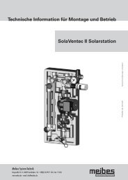
T1 = Domestic hot water<br />
T2 = Heat transfer media flow<br />
T3 = Cold water and<br />
circulation temperature<br />
T4 = Heat transfer media return<br />
T5 = Storage tank sensor for<br />
„reheating“ and release of the<br />
hot water controller and<br />
circulation<br />
P1 = Primary heat transfer pump<br />
P2 = Circulation pump<br />
DFZ = Flow rate metre<br />
1 = Heat transfer unit<br />
2 = Return flow preventer<br />
3 = Control<br />
4 = Shut-off valve<br />
5 = Flow rate restrictor 3l<br />
6 = Filling and draining tap<br />
A = Flow heating<br />
B = Return heating<br />
C = Domestic hot water outlet<br />
D = Hot water circulation<br />
E = Cold water (domestic water)
4. Installation<br />
■ The freshwater station has been pre-assembled and<br />
pre-wired.<br />
■ Installation should take place on a load-bearing dry<br />
wall.<br />
■ With a pre-formed insulating wall it is possible to<br />
mount the freshwater station directly onto a storage<br />
tank (Ø ≥ 600mm) using connectable insulation<br />
wedges (not included in delivery)<br />
■ The freshwater station should preferably be mounted<br />
low so as to be at the same height as the cold<br />
area of the stratified storage tank!<br />
■ The piping should be connected according to their<br />
relevant function (see drawing).<br />
Assembly drawing<br />
410<br />
205<br />
C D A<br />
65 65 63<br />
Wall distance to the centre lines of the connections:<br />
82mm<br />
Connectable insulation wedges<br />
for mounting the storage tank<br />
B<br />
120 50<br />
E<br />
45<br />
320<br />
100<br />
50<br />
580<br />
Example storage tank mounting<br />
Please note:<br />
■ Safeguarding the cold water should be done<br />
according to DIN 1988, i.e. with a safety group<br />
and if necessary, an expansion tank.<br />
4.1 Hydraulic connections<br />
Heat transfer media side<br />
Connection A: Flow heating 3/4“ female<br />
Connection B: Return heating 3/4“ female<br />
Plumbing<br />
Connection C: Domestic hot water outlet 3/4“ female<br />
Connection D: Hot water circulation 3/4“ female<br />
Connection E: Cold water (domestic water) 3/4“<br />
female<br />
4.2 Electrical connections<br />
Kindly observe the EVU (energy supply companies)<br />
provisions! To prevent the dry running of pumps, the<br />
freshwater station may only be switched on once<br />
the <strong>system</strong> has been filled and vented.<br />
The freshwater station is cabled in working order<br />
when delivered. The connection at the electrical supply<br />
network 230 V/ 50 Hz AC takes place via the installed<br />
power supply cable. This circuit is to be secured with a<br />
10 A line protector switch.<br />
Loading capacity of the control outputs:<br />
Triac outputs A1 and A2 for the pumps max. 1A 230 V<br />
AC Potential-free contact S1 (changeover contact) max.<br />
4A 230 V AC1<br />
Wiring diagram<br />
Temperature sensor<br />
Fuse<br />
Outputs<br />
230V/AC<br />
Power supply<br />
Pump 1<br />
Pump 2<br />
Potential-free<br />
switch outputs<br />
Boiler standards<br />
5
5. Control <strong>system</strong><br />
5.1 Display description<br />
5.2 Operating keys - description<br />
6<br />
1 2 3 4<br />
13 12 11 10<br />
key Function Description<br />
„up“<br />
„UP“<br />
„+“<br />
„down“<br />
„Open“<br />
„Down“<br />
„-“<br />
„Page left“<br />
„Quit“<br />
„Cancel“<br />
„ESC“<br />
„Page right“<br />
„Select“<br />
„Confirm“<br />
„Enter“<br />
5<br />
6<br />
7<br />
8<br />
9<br />
1 ,,Info” menu Display of all measured<br />
values and <strong>system</strong> states<br />
2 ,,Programming” menu Contains programming<br />
values which can be adjusted<br />
by the end customer.<br />
3 „Manual Mode“ menu Set/ reset the outputs,<br />
determination of the<br />
operating points<br />
4 „Basic Setting“ menu Contains all set values,which<br />
can only be adjusted after<br />
„Release“.<br />
5 Main menus<br />
6 Measuring point assignment<br />
7 Value/ units<br />
8 Additional information, e.g. temperature sensor<br />
9 Status indicator<br />
10 „OK“ symbol Confirmation of inputs/ value<br />
change/ value reset<br />
11 „Important“ symbol Group error message for all<br />
faults<br />
12 „Outputs“ symbol Indicates which switching<br />
outputs are active.<br />
13 „Pump“ symbol Indicates that the controller<br />
is active.<br />
■ Page to the next menu<br />
■ Value change: incremental increase in the displayed<br />
value, if pressed continuously the values increase continuously<br />
■ In the basic menu: Open a main menu<br />
■ Page to the next menu<br />
■ Value change: incremental reduction in the displayed value,<br />
if pressed continuously the values decrease continuously<br />
■ Page to the left in the main menu<br />
■ Quit a menu<br />
■ Quit a menu item<br />
■ Cancel a value change without saving<br />
■ Page to the right in the main menu<br />
■ Select a menu item<br />
■ Confirm a value change with save
5. Control <strong>system</strong><br />
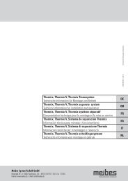
5.3 Menu structure of the V1.54 controller<br />
Information menu<br />
Shutdown 60°C<br />
Basic Setting<br />
menu<br />
Manual Mode<br />
menu<br />
Programming<br />
the menu<br />
Flow min 4 l/min<br />
Output min 7 %<br />
Flow middle 8 l/min<br />
Output middle 20 %<br />
Flow max 25 l/min<br />
Output max 76 %<br />
Correction per 5K 10 %<br />
Calibration Heating medium 75°C<br />
Calibration T cold water 15°C<br />
Calibration Setpoint 50°C<br />
Information<br />
Softw. version<br />
1.XX<br />
Output 1<br />
Pulse generator<br />
Scrolling<br />
Output 2<br />
Heat exchanger<br />
Hot water setpoint 50°C<br />
WT operating mode<br />
Cold, hot or timed<br />
heating<br />
WT setpoint 40°C<br />
WT hysteresis 3K<br />
Controller On/Off 2)<br />
Control parameters<br />
Circulation<br />
Time slot 1<br />
Time slot 2<br />
Time slot 3<br />
Drinking water T1<br />
Output 3<br />
Select<br />
Confirm<br />
Characteristic<br />
curve 1)<br />
Quit<br />
After run 0-300 s 60s<br />
Heat exchanger<br />
Outputs<br />
Whole test<br />
Reheat 3)<br />
65°C SP setpoint<br />
or<br />
15 K spread<br />
Hot water VL T2<br />
Circ. Run time 0-600 90s<br />
Circ. Rest time 1-120 min 0 min<br />
Circulation setpoint 10-50°C 40°C<br />
Cold water T3<br />
Sensor T3 or T6<br />
Circulation 1)<br />
On/Off<br />
Characteristic curve<br />
calibration<br />
Data logging 6)<br />
1s to 30s<br />
Single or cyclical<br />
recording Control<br />
Reset<br />
Hot water RL T4<br />
Activation temp 35-55°C 35°C<br />
Activation hysteresis 3-10K 3K<br />
Activation T5<br />
Off/On<br />
Reheating 1)<br />
On/Off<br />
Absolute or relative<br />
Accumulator setpoint<br />
Circulation<br />
calibration<br />
4)<br />
Time<br />
Time<br />
Date<br />
Accumulator T5<br />
6)<br />
Premixer 1)<br />
On/Off<br />
C: 14.0 H: 40.5<br />
P: %<br />
D: 5.0 T: 75.0<br />
Flow l/min<br />
7)<br />
Factory 1)<br />
configuration<br />
Off/On<br />
6,0 l/min kW WW<br />
Status<br />
P1: P2:<br />
Tapped quantity<br />
Release 1)<br />
For maintenance<br />
and settings<br />
1) Within one minute after mains connection or executable using key combination. Access<br />
is automatically blocked after 60 minutes!<br />
2) Can be run with button combination: Basic Setting menu -> Release -> Select with right<br />
click 2x -> Up, Down and Right button - press simultaneously > 2 s -> „Release On“<br />
appears -> quit with left click.<br />
3) Only visible if Reheat is active.<br />
4) On visible if T5 activation in operation.<br />
5) Only visible if a data stick is plugged in.<br />
6) Only visible through button combination: Characteristic curve adjustment alternatively<br />
7)<br />
Off<br />
Active 50= hot water control<br />
Z – active = circulation<br />
After run<br />
Controlled variables<br />
P1 % WW<br />
Controller active<br />
Flow status VL<br />
by hand<br />
7) Only visible through button combination<br />
Active outputs<br />
7
5. Control <strong>system</strong><br />
5.3.1 Explanation of menu items<br />
5.3.2 Information menu<br />
In this menu all the measured values of the temperature<br />
sensor, volumetric flow metre as well as the control<br />
<strong>system</strong> (<strong>system</strong> conditions) are displayed.<br />
Status display:<br />
Active 50 = Control <strong>system</strong> on domestic hot water<br />
set temperature value of 50°C<br />
Z - active 4 = Control <strong>system</strong> on circulation set<br />
temperature value of 40°C<br />
After-run = After-run of the circulation pump for<br />
cooling down the stainless steel plate<br />
heat exchanger (See 5.3.5)<br />
Disinfection = Control <strong>system</strong> on disinfection<br />
temperature<br />
Off = No control <strong>system</strong> function active<br />
5.3.3 Programming menu<br />
The programming menu contains values which are to be<br />
set by the end customer.<br />
■ Heat transfer unit<br />
Hot water – set value 50°C, adjustment range<br />
45°C to 60°C for domestic hot water. Should this<br />
value be increased, the 60°C temperature value of<br />
the safety shutdown should also be increased, by<br />
going in the basic setting menu, submenu<br />
„Controller“. A blending valve should in any event be<br />
installed on the freshwater station outlet!<br />
Water temperature – operating mode:<br />
cold, hot or timed heating.<br />
Water temperature – cold 1) No heat exchange<br />
media is added to the stainless steel plate heat<br />
exchanger after hot water has been drawn off. It<br />
remains at the lowest temperature level after<br />
drawing off. This results in a favourable control<br />
behaviour arising for the drawing off of hot water.<br />
Water temperature – hot 1) 2) The stainless steel<br />
plate heat exchanger is continuously kept at a<br />
constant operating temperature. When there is a<br />
deviation lower than the water temperature set value<br />
minus hysteresis, the P1 is activated with a capacity<br />
of 25 % until the water temperature set value has<br />
been achieved. This happens provided that a temperature<br />
is measured at T2 or at the “reheating” option<br />
at T5 which is greater than that of the hold-warm<br />
temperature. Should this condition not be fulfilled at<br />
T2, the temperature is again requested after a resting<br />
period of one hour.<br />
Water temperature – timed heating 1) 2) For the<br />
duration of the time slot the stainless steel plate<br />
heat exchanger is kept warm.<br />
8<br />
Water temperature – set value 2) 40°C, adjustment<br />
range 20°C to 50°C for the hold-warm temperature<br />
of the stainless steel plate heat exchanger for water<br />
temperature – hot and water temperature – timed<br />
heating.<br />
Water temperature – Hysteresis 3 K, adjustment<br />
range 1 K to 20 K for the water temperature set<br />
value. Only visible if water temperature = hot or<br />
water temperature = timed heating has been<br />
selected!<br />
Note: The water temperature – hot function should<br />
be used if the buffer storage is located far from<br />
the freshwater station and the <strong>system</strong> is<br />
operated without circulation.<br />
Hot water max. 5K (2 K – 10 K)<br />
Hot water min. 5K (2 K – 10 K)<br />
Testing period 5 min (1 min – 30 min)<br />
An error message is displayed when the temperature<br />
exceeds or is lower than the hot water set<br />
value. When the threshold values are exceeded or<br />
the temperature drops below these values, a fault is<br />
generated after the preset monitoring period, and<br />
output S2 is switched as a potential-free contact.<br />
The output is reset once the temperature is again<br />
within the temperature range or it can be reset in<br />
the information menu/error message upon actuation<br />
of the right key. This monitoring is only valid when<br />
drawing off takes place – not during circulation!<br />
■ Time slot<br />
There are tree time slots available to set the<br />
circulation. Should the switch-on and the switch-off<br />
time be set the same, this time slot is no longer<br />
active. For further circulation functions, see 5.3.3.<br />
The time slots are also used for the water tempera-<br />
ture - timed heating. (See 5.3.3)<br />
■ Reheating<br />
This menu item is only visible once the reheating<br />
function has been activated in the basic setting<br />
menu. If „absolute value” has been selected, „65°C<br />
storage tank set value” will be displayed. This value<br />
is adjustable between 20°C and 90°C. If „relative<br />
value” is selected „15 K splay” is displayed here.<br />
This value is adjustable between 2 K and 50 K.<br />
For further information regarding functions, see<br />
points 5.3.5 and 7.4. Storage tank set value = buffer<br />
set value<br />
■ Data logging<br />
This menu is only visible if a data stick has been<br />
connected to the front side of the control <strong>system</strong>.<br />
Measured values can be recorded on this data stick.<br />
In a measurement interval of 1 second (factory<br />
setting) measured values for approx. 4.5 hours can<br />
be logged. The data can be analysed at the plant<br />
with special software.<br />
■ Clock time<br />
Submenu for setting the clock time, date and the day<br />
of the week.
5. Control <strong>system</strong><br />
1) Based on the physical fact that the existing heat<br />
energy in the heat transfer unit has to be controlled<br />
by the control <strong>system</strong>, short-term temperature<br />
fluctuations at the start of a hot water tapping<br />
cannot be ruled out completely. Favourable control<br />
behaviour is achieved with the water temperature –<br />
cold function, which results in very short or no<br />
reheating time!<br />
2) The plate heat exchanger is kept hot by the heat<br />
exchange media from the buffer. The heat exchange<br />
media can take on temperatures of more than 60°C.<br />
Please note that such temperatures can result in<br />
calcium oxide precipitation!<br />
5.3.4 Manual operation menu<br />
■ The output 1, output 2, output 3 and outputs<br />
„overall test” can be switched on and off manually,<br />
in order to check the functioning of the pumps.<br />
■ Characteristic curve calibration<br />
Here the regulation of the characteristic curve is<br />
determined during the initial operation. (See 6.3.2)<br />
■ Circulation adjustment<br />
In this menu item the circulation adjustment is<br />
carried out.(See 6.3.3)<br />
5.3.5 Basic setting menu<br />
This menu contains important technical information and<br />
parameters for controlling, which may be modified by<br />
a specialist tradesman. In order to modify values, the<br />
submenu “release” in the basic setting menu has to be<br />
activated. (See 8)<br />
■ Informationen<br />
Here information regarding the software and <strong>system</strong><br />
version is given.<br />
■ Controller ON/OFF 3)<br />
Amongst other things, this menu item contains the<br />
safety shutdown for a domestic hot water temperature<br />
of 60°C. Should this temperature be exceeded<br />
at T1, pump P1 switches off until the temperature<br />
drops to below 60°C. This value should be increased<br />
when the hot water – set value is increased.<br />
However, a blending valve should additionally be<br />
mounted on the domestic hot water outlet of the<br />
freshwater station. The other control parameters<br />
should not be adjusted!<br />
■ Pulse generator 2)<br />
These values are used to adapt the flow rate<br />
generator at the control <strong>system</strong>.<br />
■ Characteristic curve 2)<br />
In this menu item the pre-determined operating<br />
points of the control <strong>system</strong> can be read.<br />
In this menu item the pre-determined operating<br />
points of the control <strong>system</strong> can be read. Likewise<br />
the default value for flow max. of the characteristic<br />
curve calibration can be modified. Should, for<br />
example, the 25l/mm for the characteristic curve at<br />
flow max. not be reached, the default value for flow<br />
max. can be lowered to 15l/mm. (See 6.3.2)<br />
■ Heat transfer unit<br />
After run 2)<br />
Outside the circulation time and after a drawing off of<br />
hot water, it is possible to keep the circulation pump<br />
running afterwards. The stainless steel plate heat<br />
exchanger is cooled down and its decalcification is<br />
counteracted. The function of the after-run, from an<br />
energy point of view, is only meaningful and possible<br />
outside the circulation time!<br />
■ Circulation ON/OFF<br />
If this function has been activated, up to three time<br />
slots can be set in the „programming” menu.<br />
In the time slot, controlling is always based on the<br />
circulation temperature. If the time slot has ended, or<br />
drawing off takes place or the circulation temperature<br />
has been reached, the circulation switches off. It is<br />
attached to the circulation rest time. No circulation<br />
can be activated in the circulation rest time. To avoid<br />
the heat transfer media in the buffer from being<br />
mixed, the heat transfer media temperature is<br />
checked at the heat transfer media- flow- sensor<br />
T2 or with the option at T5 at the start of the circulation<br />
process, to ensure that the heat transfer media<br />
temperature is greater than the circulation set<br />
temperature +2K. This happens at T2 with the<br />
following procedure: The heat transfer pump P1 runs<br />
for 5 minutes at minimal capacity. Should the<br />
circulation set temperature plus 2K not be attained<br />
after expiry of the 5 minute run time, the heat<br />
transfer pump P1 is switched off – and restarts the<br />
process again after a waiting period of one hour.<br />
Following this, the flashing message „error<br />
message flow temperature” will be seen on the<br />
display in the information menu.<br />
Flow increase 5 K<br />
In some cases (high temperature drops in circulation<br />
capacity), the circulation return temperature is<br />
not reached. The set value of the circulation temperature<br />
(flow increase 5K) can be increased up to 20 K.<br />
The input is limited to the hot water set temperature<br />
value. Should the hot water set temperature be<br />
reduced, the flow increase value for circulation is<br />
also reduced!<br />
Example:<br />
Circulation set = 35°C, hot water set = 50°C, flow<br />
Increase = 15 K possible<br />
Circulation set = 40°C, hot water set = 50°C, flow<br />
Increase = 10 K possible<br />
Circulation set = 40°C, hot water set = 45°C, flow<br />
Increase = 5 K possible<br />
9
5. Control <strong>system</strong><br />
If a buffer sensor T5 is available as an option for the<br />
activation of the reheating function and its temperature<br />
is less than the circulation temperature + 2K, the<br />
circulation is then discontinued.<br />
As a result of the reheating function it is to be assumed<br />
that after reheating and for a conceivable period of<br />
time thereafter sufficient temperature is available in the<br />
buffer.<br />
Outside the active time slot, the circulation is always<br />
in the “pulse generated” mode, i.e. always when a<br />
drawing off of approx. 1 s has been carried out, the<br />
circulation pump is switched on for the programmed<br />
time in “circulation-running time” and the circulation is<br />
then also blocked from being reactivated for the preset<br />
“circulation-rest time” period.<br />
Circulation running time = 300 s<br />
From 0 – 600 s adjustable running time of the circulation<br />
pump.<br />
Circulation rest time = 5 min<br />
From 0 – 120 min adjustable blocking time for<br />
reactivating the circulation.<br />
Circulation hot water set value = 40°C<br />
From 10°C to 50°C adjustable temperature for circulation<br />
in the time slot.<br />
Sensor TF3 = select sensor T3 or T6 (optional)<br />
In the factory setting T3 is used for measuring the<br />
circulation temperature. However, an independent<br />
sensor T6 (optional) can also be used directly in the<br />
circulation pipes for this purpose.<br />
Option T5: With an additional sensor T5 (optional),<br />
which is installed in the buffer, two further functions<br />
can be activated.<br />
■ Activation T5<br />
If the activation T5 = on is selected, it is possible to<br />
only put the control <strong>system</strong> into operation after a<br />
specified buffer temperature has been attained.<br />
Factory setting = off<br />
Switch-on temperature = 35°C temperature<br />
(adjustment range 35°C to 55°C)<br />
Hysteresis = 3 K<br />
(adjustment range 3 K to 10 K)<br />
■ Reheating ON/OFF<br />
Optionally the additional „reheating” function can be<br />
activated. When there is a deviation lower than an<br />
adjustable set value for the buffer, this function is an<br />
external heat source which is activated to reheat<br />
the buffer until it reaches the set level.<br />
The requirement for this is that the heat source is<br />
actually able to supply the desired temperature level.<br />
For this purpose the contact S1 on the controller<br />
circuit board is used. This contact can be charged<br />
with 4 A 230 V AC. The set value for the storage<br />
temperature can be defined as an absolute value<br />
(fixed value e.g.: 65°C) or as a relative value.<br />
10<br />
Should the relative value be used, the set value for<br />
the buffer temperature is calculated from the<br />
programmed hot water – set temperature + the<br />
entered value for the „splay”. e.g.: hot water set<br />
temperature 50°C + splay 20 K = 70°C buffer<br />
temperature. Should the programmed or calculated<br />
set value deviate lower by 3 K, the external heat<br />
source is kept activated until the set value is reached<br />
again. The temperature values needed for this can be<br />
set in the programming menu, under the submenu<br />
“reheating”. (See 5.3.3)<br />
■ Pre-mixer ON/OFF<br />
As a rule, this selection is not active in this control<br />
<strong>system</strong>!<br />
■ Disinfection<br />
The “disinfection” function can be activated in the<br />
basic setting menu, but only if there is a circulation<br />
pipe available. The circulation return temperature is<br />
controlled, which is measured at the cold water<br />
sensor. This temperature must be attained for the<br />
preset disinfection time period. Short-term lower<br />
temperature deviations are corrected. In total, the<br />
actual time that the set temperature was attained,<br />
is counted. Should the flow temperature for the<br />
control <strong>system</strong> not be achieved, a corresponding<br />
error message is sent to the information menu after<br />
30 minutes. During the disinfection of the hot water<br />
and circulation pipes, very high temperatures are<br />
achieved. There is therefore a danger of scalding!<br />
Qualified personnel should take the necessary<br />
precautions for the protection of persons and<br />
property!<br />
■ Factory setting ON/OFF<br />
Should the controller be set back to the original<br />
factory positions as on delivery, this menu item is to<br />
be activated.<br />
■ Release<br />
In order to „unlock“ the controller for different<br />
settings, the following should be done:<br />
Release by pressing the right key twice and<br />
“OFF” will flash. Press UP and DOWN and right<br />
key simultaneously for approx. 2s and release<br />
changes to „ON“. To subsequently leave the setting,<br />
press the left key.<br />
The same operating sequence is used to block<br />
access to the controller. Alternatively, this takes<br />
place automatically after 60 minutes.<br />
2) This is executable within one minute after mains<br />
connection or by using the key combination. Access<br />
is automatically blocked after 60 minutes.<br />
3) Only possible to activate „release” by using the<br />
key combination in the menu. Access is automatically<br />
blocked after 60 minutes.
6. Initial operation and <strong>system</strong> calibration<br />
6.1 Flushing and filling the<br />
<strong>system</strong><br />
■ The entire <strong>system</strong> should be flushed before filling.<br />
■ The flat-sealing connections of the freshwater station<br />
should be checked for leakage and the connections<br />
should be tightened, if necessary. When tightening<br />
the connections, always use the appropriate tools to<br />
counter-resist!<br />
■ Air which has accumulated in the heating <strong>system</strong><br />
should be removed by opening the vent screw.<br />
Caution:<br />
In doing so, pay attention to the <strong>system</strong> pressure and<br />
refill, if necessary.<br />
6.2 Controller calibration<br />
Why is it necessary to calibrate the controller?<br />
In doing the controller calibration and the subsequent<br />
circulation adjustment, the values of the freshwater<br />
station is optimised and adapted to the local conditions.<br />
In the calibration menu you will be requested to draw<br />
hot water three times. In doing so, the operational<br />
points are determined for the control <strong>system</strong> and are<br />
independently taken over into the control <strong>system</strong>.<br />
The control <strong>system</strong> then operates on the characteristic<br />
curve so recorded. Under optimal conditions this<br />
process takes10 to 15 minutes. The subsequent<br />
circulation adjustment connected to this process,<br />
serves to log the volumetric flow of the circulation.<br />
Note: Please draw off hot water for a longer period<br />
before calibration so that stable temperature conditions<br />
for cold water and hot water can be set at the freshwater<br />
station.<br />
6.3 Calibration procedure<br />
1. Pump capacity<br />
2. Characteristic curve calibration<br />
3. Circulation adjustment<br />
6.3.1 Selecting pump capacity<br />
UPS15-60 pump stage I for drawn off amounts up to<br />
15 litres<br />
UPS15-60 pump stage II for drawn off amounts up<br />
40 litres<br />
Operating at pump stage II is generally recommended<br />
for low buffer temperatures.<br />
6.3.2 Characteristic curve<br />
calibration<br />
A buffer temperature which lies above the domestic hot<br />
water temperature is necessary for the characteristic<br />
curve calibration. The relevant amounts are found at 2.1<br />
Performance characteristics!<br />
Determining the control <strong>system</strong> operating<br />
points<br />
1. Select the “manual” menu<br />
2. Select the “characteristic curve calibration” submenu<br />
3. Select using the right key; „OFF“ flashes; Use<br />
upper key to go on “ON”; confirm with right key<br />
twice and start a 25 litre hot water tapping according<br />
to the menu navigation. After approx. three minutes<br />
you will be requested to reduce the hot water discharge<br />
volume to 8 litres. After a further approx. three minutes<br />
you will again be requested to reduce the hot water<br />
discharge volume (4 litres).<br />
4. If thereafter the “characteristic curve calibration on”<br />
is displayed again, leave this submenu using the left<br />
key. The characteristic curve calibration is now<br />
complete and the values are independently logged<br />
into the control <strong>system</strong>.<br />
5. Should it not be possible to draw off a volume of<br />
25l/min, the value for “flow max.” can be reduced to<br />
another value e.g. 15l/min. Additionally, a change into<br />
the “flow max” is required in the basic setting menu,<br />
submenu characteristic curve by using the “UP” or<br />
“DOWN” keys, and to select using the right key. The<br />
display 25l/min flashes and can be reduced by using<br />
the “DOWN” key. Thereafter, confirm this setting by<br />
pressing the right key twice.<br />
11
6. Initial operation and <strong>system</strong> calibration<br />
6.3.3 Circulation adjustment<br />
A circulation adjustment is to be undertaken if the<br />
freshwater station is fitted with a circulation pump and<br />
a circulation pipe is connected to it! For the controller to<br />
detect a withdrawal of water, the actual circulation cycle<br />
must be known as the flow rate is always measured by<br />
the sum of the hot water withdrawal and the overlaying<br />
circulation.<br />
Information for a software update:<br />
As of software version V 1.54 the 3 l/min flow rate<br />
restrictor can be left out.<br />
A prerequisite for the calibration is that all hot water<br />
tapping points are closed.<br />
Procedure to be followed:<br />
■ select: manual menu<br />
■ menu item „circulation adjustment“<br />
■ select by using the right key,<br />
„OFF“ flashes<br />
■ using the „UP“ key change to „ON“<br />
■ confirm twice using the right key<br />
■ the message “flowing” is displayed<br />
■ when the message „Circulation calibration<br />
complete“ is displayed, measuring has been<br />
finished. The measured value is displayed<br />
and independently logged into the control<br />
<strong>system</strong>.<br />
■ Leave the menu using the left key<br />
12
6. Initial operation and <strong>system</strong> calibration<br />
6.3.4 Detailed description of<br />
characteristic curve<br />
calibration<br />
Characteristic<br />
curve off<br />
calibrate<br />
Characteristic<br />
curve on<br />
calibrate<br />
Withdrawal<br />
starts<br />
Determining the operating points of the<br />
control <strong>system</strong><br />
■ Manual operation menu<br />
■ Characteristic curve calibration submenu<br />
1x Leave the info menu using the “escape” key<br />
2x<br />
flashes<br />
5x<br />
and then<br />
1x<br />
flashes<br />
1x<br />
2x<br />
1x<br />
Select the menu: manual operation<br />
Select the menu: manual operation<br />
■ select using right key, OFF flashes.<br />
■ Using the upper key, switch to On and<br />
■ confirm twice with the right key.<br />
Calibration procedure starts.<br />
Kindly follow the menu guidance on the<br />
display.<br />
Consecutive drawn amounts of 25 litres,<br />
8 litres and 4 litres are required. After the<br />
relevant operating points of the pump have<br />
been determined and independently logged<br />
into the control <strong>system</strong>, characteristic curve<br />
calibration “on” again appears on the display.<br />
Leave this submenu using the left key.<br />
The characteristic curve calibration is now<br />
complete.<br />
13
7. System examples<br />
7.1 Freshwater station with<br />
circulation in a time-slot<br />
and with tapping detection<br />
outside the time slot<br />
■ Initial operation and <strong>system</strong> calibration from point 6<br />
■ Setting the time and date, point 5.3.3<br />
■ Domestic hot ■ set value e.g.: 50°C, point<br />
water 5.3.3 and 5.3.5<br />
■ Circulation ■ Basic setting menu,<br />
Circulation submenu = select<br />
“on”, point 5.3.5<br />
■ In programming menu,<br />
circulation submenu up<br />
to 3 select time slot,<br />
point 5.3.3<br />
■ Circulation temperature 40°C,<br />
for control in time slot,<br />
point 5.3.5<br />
■ Circulation time e.g.: 60 s,<br />
Circulation rest time.: e.g.<br />
10 min, for controlling the<br />
circulation through tapping<br />
detection outside the<br />
time slot, point 5.3.5<br />
■ Heat transfer unit ■ WT = cold, point 5.3.3<br />
■ Time lag ■ e.g.: 20 s, point 5.3.5<br />
7.2 Freshwater station with<br />
circulation only via tapping<br />
detection<br />
■ Initial operation and <strong>system</strong> calibration from point 6<br />
■ Setting the time and date, point 5.3.3<br />
■ Domestic hot ■ set value e.g.: 50°C,<br />
water point 5.3.3 and 5.3.5<br />
■ Circulation ■ Basic setting menu,<br />
Circulation submenu = select<br />
“on”, point 5.3.5<br />
■ In programming menu,<br />
Circulation submenu is the<br />
start and stop times within<br />
each 3 time slots which are<br />
to be set at the same time<br />
e.g.: start 6h00 - stop 6h00<br />
point 5.3.3<br />
■ Circulation time e.g.: 60 s,<br />
Circulation rest time e.g.:<br />
10 min, point 5.3.5<br />
■ Heat transfer unit ■ WT = cold, point 5.3.3<br />
■ Time lag ■ e.g.: 20 s, point 5.3.5<br />
14<br />
7.3 Freshwater station without<br />
circulation<br />
■ Initial operation and <strong>system</strong> calibration from point 6<br />
■ Setting the time and date, point 5.3.3<br />
■ Domestic hot ■ set value e.g.: 50°C, point<br />
water 5.3.3 and 5.3.5<br />
■ Circulation ■ Basic setting menu,<br />
Circulation submenu = select<br />
“off”, point 5.3.5<br />
■ Heat transfer unit ■ WT = cold can be selected,<br />
if the distance between<br />
the buffer and the freshwater<br />
station is not too great.<br />
After-run e.g.: 20 s,<br />
point 5.3.5<br />
■ WT = hot can be selected,<br />
if there is a great distance<br />
between the buffer and the<br />
freshwater station, and the<br />
comfort of the “rapid” hot<br />
water drawing has been<br />
attained. Set the after-run<br />
point 5.3.5 on nought, as no<br />
circulation pipe is available.
7. System examples<br />
7.4 Freshwater station with<br />
reheating option and/or<br />
activation<br />
The freshwater station with or without circulation can be<br />
extended by two functions via an additional temperature<br />
sensor T5 (not included in delivery) in the buffer. These<br />
functions must be activated in the basic setting menu.<br />
Point 5.3.5<br />
The temperature sensor T5 becomes visible in the<br />
information menu after activation.<br />
1. A boiler must be requested to reheat the buffer.<br />
For this a potential-free contact S1 on the control<br />
circuit board is used.<br />
This contact can be charged with 4 A 230 V AC.<br />
A description as well as the settings for the reheating<br />
option is found under point 5.3.5, reheating menu<br />
item.<br />
2. The same temperature sensor T5 can be used to<br />
specify the buffer temperature, from where the hot<br />
water regulation and the circulation are activated.<br />
This function makes sense if the buffer temperature<br />
could at some point take on unfavourably low values<br />
as a result of renewable energy sources, and if the<br />
freshwater station should not yet run at such low<br />
buffer temperatures.<br />
A description as well as the settings for the option<br />
activation can be found under point 5.3.5, Activation<br />
menu item.<br />
7.5 Increasing the domestic<br />
water set value<br />
The following example is used to show what factors<br />
should be taken into account when the domestic hot<br />
water temperature is to be increased from 50°C to 60°C:<br />
1. WW – set value increase<br />
2. Increase the electronic safety shutdown and install a<br />
blending valve.<br />
3. Carry out a characteristic curve calibration!<br />
re 1. In the programming menu, submenu heat transfer,<br />
increase the hot water set value from 50°C to<br />
60°C. To do this, select 50°C with the right key.<br />
Once 50°C flashes, the value can be increased<br />
to 60°C by using the upper key. Thereafter, confirm<br />
by pressing the right key twice.<br />
re 2. Release the operating level for the specialist<br />
tradesmen in the basic setting menu. See point 7.<br />
In the programming menu, submenu controller,<br />
increase the menu item 60°C deactivation from<br />
60°C to 70°C. To do this, the submenu controller<br />
must be selected by pressing the right key once<br />
until the bracket goes out. Then press the lower<br />
key once. 60°C activate will be displayed. Now<br />
select by pressing the right key once until the<br />
60°C flashes. Using the upper key, increase to<br />
70°C and confirm by pressing the right key twice.<br />
You have now increased the safety shutdown<br />
(scalding protection) of the control <strong>system</strong> to a<br />
higher value and must now re-install a blending<br />
valve on the hot water outlet!<br />
re 3. Characteristic curve calibration see point 6.2 to<br />
6.3.2<br />
15
7. System examples<br />
7.6 Freshwater station as<br />
cascade connection<br />
Should larger volumes of hot water be needed, overflow<br />
valves allow for the interconnection of two or more<br />
freshwater stations as a cascade. Here, the service<br />
water circulation module can be left out for the second<br />
and other freshwater stations.<br />
The circulation is controlled only by the first freshwater<br />
station.<br />
Basic circuit diagram:<br />
Second station First station<br />
Required accessories:<br />
Overflow valve DN 25 for<br />
Cascade connection<br />
Adjustment range:<br />
100 to 500 mbar<br />
Article no.: 69072.9<br />
16<br />
Domestic water<br />
hot<br />
Domestic water<br />
cold<br />
7.6.1 Initial operation and<br />
<strong>system</strong> calibration of the<br />
freshwater cascade<br />
First station<br />
■ Initial operation and <strong>system</strong> calibration from point 6<br />
■ Setting the time and date, point 5.3.3<br />
■ Domestic hot ■ set value e.g.: 50°C, point<br />
water 5.3.3 and 5.3.5<br />
■ Circulation ■ Basic setting menu,<br />
Circulation submenu = select<br />
“on”, point 5.3.5<br />
■ In programming menu,<br />
circulation submenu up to<br />
3 select time slot, point 5.3.3<br />
■ Circulation temperature<br />
40°C, for control in time slot,<br />
point 5.3.5<br />
■ Circulation time e.g.: 60 s,<br />
Circulation rest time.: e.g.<br />
10 min, for controlling the<br />
circulation through tapping<br />
detection outside the time<br />
slot, point 5.3.5<br />
■ Heat transfer unit ■ WT = cold, point 5.3.3<br />
■ Time lag ■ e.g.: 20 s, point 5.3.5<br />
Second station<br />
■ Initial operation and <strong>system</strong> calibration:<br />
The determined values of the characteristic curve<br />
calibration of the first station are taken over. These<br />
values are read in the first control <strong>system</strong> in the<br />
basic setting menu, characteristic curve submenu<br />
and in the same menu they are set in the second<br />
control <strong>system</strong>.<br />
■ Setting the time and date, point 5.3.3<br />
■ Domestic hot ■ Set value e.g.: 50°C,<br />
water point 5.3.3 and 5.3.5<br />
■ Circulation off<br />
■ Heat transfer unit ■ WT = cold, point 5.3.3<br />
■ After-run ■ e.g.: 20 s, point 5.3.5<br />
Differential pressure-overflow valve<br />
Hot water should be drawn off of e.g.: 35l/min.<br />
This domestic water volumetric flow can be read in<br />
the control <strong>system</strong> information menu of the first<br />
freshwater station. Set the differential pressureoverflow<br />
valve so that the second freshwater station<br />
starts operating (determination of opening pressure of<br />
the overflow valve). Loosen the locking screw at the<br />
differential pressure-overflow valve. Afterwards the<br />
opening pressure can be adjusted in stages by turning<br />
the hand wheel valve. The selected position should<br />
subsequently be checked at the locking screw to<br />
ensure it against accidental adjustment.
7. System examples<br />
7.7 Disinfecting the hot water<br />
and circulation pipes<br />
During the disinfection of the hot water and circulation<br />
pipes, very high temperatures are generated.<br />
There is a danger of scalding!<br />
Qualified personnel should take the necessary<br />
precautions for the protection of persons and property!<br />
8. Releasing operating level for specialist<br />
tradesmen!<br />
■ In the basic setting menu press the „down“ key<br />
downwards nine times until submenu release is<br />
attained [values].<br />
■ Now press „right” key twice, this causes “off” to<br />
flash.<br />
■ Press the „up“ and „down“ and „right“ keys<br />
simultaneously for approx. 2 s, release switches<br />
to “on”.<br />
■ Thereafter leave the menu by using the “left” key.<br />
The releasing of the operating level can be reset again in the same way.<br />
Access to the adjustable values is blocked automatically after 60 minutes!<br />
Example for setting the control <strong>system</strong>:<br />
1. Release the operating level for the specialist<br />
tradesmen in the basic setting menu.<br />
2. In the basic setting menu, submenu<br />
disinfection, select “in”.<br />
3. Set the hot water set value.<br />
Adjustment range 65 - 75°C<br />
4. Select disinfection time (duration of<br />
disinfection) Adjustment range 0 - 60 minutes<br />
5. Select the day, week day or daily.<br />
6. Start time (0 - 24 hours)<br />
This function should be deactivated after<br />
disinfection! The function is described in<br />
5.3.5!<br />
17
9. Trouble-shooting<br />
The following is to be checked if the domestic hot water<br />
temperature is not reached:<br />
■ System voltage (fuses)<br />
■ Buffer temperature<br />
■ Vent the freshwater station<br />
■ A temperature sensor interruption or a short circuit<br />
is displayed in the information menu by a flashing<br />
general error message and is shown individually<br />
when requesting each sensor.<br />
■ Carry out characteristic curve calibration, from<br />
point 6.3.2.<br />
■ Carry out a circulation adjustment, point 6.3.3.<br />
■ During a hot water withdrawal, the circulation pipe<br />
becomes cold.<br />
Cause: The return flow preventer in the connecting<br />
nipple above the circulation pump can start leaking<br />
due to soiling in the cold water network.<br />
■ Flow rate metre: To check this, a hot water tapping<br />
is required and the flow in litres per minute read in<br />
the information menu. An intact flow rate metre<br />
should show a relatively constant value. Should<br />
fluctuations occur, check whether this comes from<br />
the domestic water network, for example in pressure<br />
increase <strong>system</strong>s<br />
■ Set the freshwater station according to the <strong>system</strong><br />
examples.<br />
■ The pumps P1 and P2 run alternatively and the status<br />
display in the information menu switches between<br />
active 50, after-run and off.<br />
■ Carry out a circulation adjustment, point 6.3.3.<br />
■ After several months of smooth running operation<br />
the hot water capacity is no longer reached.<br />
■ If a dirt filter has been installed in front of the<br />
station, this should be cleaned.<br />
■ Check return flow preventer.<br />
■ Vent the buffer and the freshwater station<br />
18<br />
■ A short time after drawing off hot water at the tap<br />
(e.g.: washbasin) the hot water temperature drops<br />
sharply even though the control <strong>system</strong> displays<br />
e.g.: 50°C hot water temperature.<br />
■ The return flow preventer should be checked in<br />
the connecting nipple above the circulation pump<br />
to see if it leaks as a result of soiling in the cold<br />
water <strong>system</strong> and if cold water has been<br />
pressed into the circulation piping.<br />
■ The circulation does not work:<br />
■ Carry out circulation adjustment!<br />
■ Check time slot!<br />
■ The temperature of the heat transfer media<br />
in the buffer is too low.<br />
The circulation set temperature + 2 K is not<br />
being reached at T2 or at T5, if present.<br />
(see point 5.3.5 Circulation)<br />
Please ensure that there is a sufficient quantity<br />
of heat in the buffer!<br />
With option T5 „reheat buffer“, a type of boiler<br />
can be activated.
10. Factory setting and personal setting<br />
Menu Submenu<br />
Heat transfer unit<br />
Circulation<br />
Circulation<br />
adjustment<br />
Factor<br />
setting<br />
Hot water set value 50°C<br />
Water temperature (WT)<br />
operating mode hot / cold / timed<br />
heating<br />
cold<br />
Hot water set value 40°C<br />
Water temperature hysteresis 3 K<br />
Hot water max 5 K<br />
Hot water min -5 K<br />
Test time 5 min<br />
Time slot 1<br />
Time slot 2<br />
Time slot 3<br />
Volumetric flow rate<br />
Circulation<br />
6:00 - 9:00<br />
11:00 - 13:00<br />
16:00 - 20:00<br />
Pulse generator 72 lmp. / litre<br />
Characteristic curve<br />
Flow min 4 l/min<br />
Capacity min 8 %<br />
Flow middle 8 l/min<br />
Capacity middle 20 %<br />
Flow max 25 l/min<br />
Capacity max 76 %<br />
Correction 5 K 10 %<br />
Heat transfer media adjustment 75°C<br />
Temperature - cold water adjustment 15°C<br />
Se value adjustment 50°C<br />
Heat transfer unit After - run 20 s<br />
Circulation<br />
Activation T5<br />
3 l<br />
On/Off on<br />
Running time 90 s<br />
Rest time 0 min<br />
Set value 40°C<br />
Flow increase circulation 5 K<br />
Temperature sensor 3 or 6 TF3<br />
On or Off Off<br />
Temperature 35°C<br />
Hysteresis 3 K<br />
Reheating On/Off Off<br />
absolute or relative absolute<br />
Pre-mixer On/Off Off<br />
Disinfection On/Off Off<br />
Hot water set value Off<br />
Disinfection time 70°C<br />
Start Monday<br />
Start 1:00<br />
UPS 15-60 Pump stage 2<br />
Personal<br />
setting<br />
19
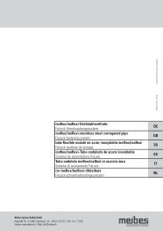
11. Diagrams<br />
Pressure loss [bar]<br />
20<br />
Volumetric current-pressure loss diagram<br />
LogoFresh Freshwater Station Compact electronically controlled<br />
Primary side<br />
hot water volume flow (I/h)<br />
Characteristic Kennlinie curve Grundfos Grundfos UPS 15-60 UPS 15-60
11. Diagrams<br />
Pressure loss [bar]<br />
Volumetric current-pressure loss diagram<br />
LogoFresh Freshwater Station Compact electronically controlled<br />
Secondary side<br />
Domestic hot water drawing volume [l/h]<br />
Domestic hot water drawing volume [l/h]<br />
21