inoflex-Edelstahlwellrohr mit FixLock - Meibes
inoflex-Edelstahlwellrohr mit FixLock - Meibes
inoflex-Edelstahlwellrohr mit FixLock - Meibes

You also want an ePaper? Increase the reach of your titles
YUMPU automatically turns print PDFs into web optimized ePapers that Google loves.
Technische Information für Montage und Betrieb<br />
Technical information for installation and operation<br />
Documentation technique pour le montage et la mise en service<br />
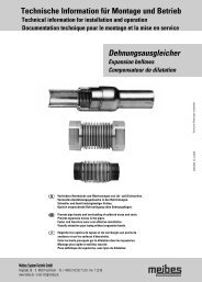
<strong>inoflex</strong>-<strong>Edelstahlwellrohr</strong> <strong>mit</strong> <strong>FixLock</strong> -<br />
Verschraubungstechnik<br />
<strong>inoflex</strong> stainless steel corrugated pipe with <strong>FixLock</strong> -<br />
fastening technology<br />
du tube ondulé en acier inoxydable <strong>inoflex</strong> -<br />
avec technique de vissage <strong>FixLock</strong><br />
<strong>Meibes</strong> System-Technik GmbH<br />
Ringstraße 18 · D - 04827 Gerichshain · Tel. + 49(0) 3 42 92 7 13-0 · Fax 7 13-50<br />
www.meibes.de · e-mail: info@meibes.de<br />
Technische Änderungen vorbehalten<br />
PR 24002.826 03-11-2008
Inhalt<br />
Table of contents<br />
Table des matières<br />
D GB F<br />
Kapitel Titel Chapter Title Chapitre Titre Seite/ Page/ Page<br />
1 Sicherheitshinweise Safety notes Consignes de sécurité 2<br />
2 Einsatzbereiche Applicability Domaines d’application 3<br />
3. Werkstoffe Materials Matériaux 3<br />
3.1 Wellrohrleitungen Corrugated pipes Canalisations ondulées 3<br />
3.2 Anschlussverschraubungen crew connections Raccords à vis 3<br />
4. Montagehinweise Installation notes Instructions de montage 4<br />
4.1 Allgemeine Montagehinweise Installation notes Instructions de montage 4<br />
4.2 Zulässige Betriebstemperatur Allowable operating temperature Température et pression 6<br />
und zulässiger Betriebsdruck and operating pressure effectives autorisées<br />
4.3 Er<strong>mit</strong>tlung des dynamischen Determining dynamic Calcul de la perte 7<br />
Druckverlustes pressure drop manométrique dynamique<br />
4.4 Zulässige Biegeradien Allowable bending radii Rayons de courbure autorisés 8<br />
4.5 Zulässige Einbausituationen Allowable installation situations Possibilités de montage 8<br />
5. Verschraubung Screw connection Fixation 9<br />
5.1 <strong>FixLock</strong> - <strong>FixLock</strong> - Fixlock - 9<br />
werkzeuglose Verschraubung tool-less screw joint Fixation sans outils<br />
5.2 Flachdichtende - Verschraubung Flat sealing screw joint Fixation à joint plat 10<br />
1
1. Sicherheitshinweise<br />
Safety notes<br />
Consignes de sécurité<br />
2<br />
D<br />
Sicherheitshinweise<br />
Bitte befolgen Sie diese Sicherheitshinweise genau, um<br />
Gefahren und Schäden für Menschen und Sachwerte auszuschließen.<br />
Zielgruppe<br />
Diese Anleitung richtet sich ausschließlich an autorisierte<br />
Fachkräfte.<br />
Vorschriften<br />
Beachten Sie bei Arbeiten<br />
■ die gesetzlichen Vorschriften zur Unfallverhütung<br />
■ die gesetzlichen Vorschriften zum Umweltschutz<br />
■ die berufsgenossenschaftlichen Bestimmungen<br />
■ die einschlägigen und für den Einsatz relevanten<br />
Sicherheitsbedingungen der DIN, EN, DVGW, TRGI, TRF<br />
und VDE u.a.<br />
■ alle regional gültigen Vorschriften und Normen<br />
GB<br />
Safety notes<br />
Please follow these safety notes precisely in order to exclude<br />
dangers and damages to people and property.<br />
Target group<br />
These instructions are intended exclusively for authorised<br />
experts.<br />
Provisions<br />
During work, observe<br />
■ the legal guidelines for accident prevention<br />
■ the legal guidelines for environmental protection<br />
■ the trade association’s regulations<br />
■ the applicable and relevant safety regulations of DIN, EN,<br />
DVGW, TRGI, TRF, and VDE, among others<br />
■ all applicable regional norms and guidelines<br />
F<br />
Consignes de sécurité<br />
Veuillez respecter scrupuleusement ces consignes de sécurité<br />
afin de ne pas mettre des personnes en danger ni end<br />
ommager les biens réels.<br />
Groupe cible<br />
Cette notice s’adresse exclusivement au personnel qualifié<br />
autorisé.<br />
Consignes<br />
Au moment d’exécuter les travaux, respectez<br />
■ les consignes légales en matière de prévention des<br />
accidents<br />
■ les consignes légales en matière de protection de<br />
l’environnement<br />
■ les dispositions de l’association préventive des accidents<br />
du travail<br />
■ les règlements de sécurité spécialisés correspondant à<br />
l’utilisation<br />
(notamment DIN, EN, DVGW, TRGI, TRF et VDE)<br />
■ toutes les consignes et normes régionalement applicables<br />
Vor Gebrauch Monteageanleitung lesen<br />
- Read the assembly instructions before use<br />
- Avant l'utilisation, lire les instructions de<br />
montage<br />
Schnittgefahr<br />
- Risk of cutting<br />
- Risque de se couper<br />
- Quetschgefahr<br />
- Risk of crushing<br />
- Risque de se couper<br />
- Gefahr erhöhter Temperatur<br />
- Risk of increased temperature<br />
- Risque de haute température<br />
- Gefahr elektrischer Spannung<br />
- Risk of electrical voltage<br />
- Danger dû à la tension électrique<br />
- Sturzgefahr bei der Montage<br />
- Risk of dropping during assembly<br />
- Risque de tomber lors du montage
2. Einsatzbereiche<br />
Applicability<br />
Domaines d’application<br />
2.1 Klima-, Lüftungs und Haustechnik<br />
Heating, ventilation, air conditioning and<br />
refreshing (HVCAR)<br />
Génie climatique, domotique et et d'aération<br />
DN 12 - DN 25 200 °C 16 bar<br />
DN 32 110 °C 10 bar<br />
2.2 Solar<br />
Solar<br />
Solaire<br />
DN 12 - DN 25 200 °C 16 bar<br />
3. Werkstoffe<br />
Materials<br />
Matériaux<br />
3.1 Wellrohrleitungen<br />
D<br />
Corrugated pipes<br />
Canalisations ondulées<br />
<strong>inoflex</strong>-<strong>Edelstahlwellrohr</strong> besteht aus rostfreiem Edelstahl<br />
(Mat.- Nr. 1.4404)<br />
GB<br />
<strong>inoflex</strong> stainless steel corrugated pipe is made of stainless<br />
steel (Mat. No. 1.4404)<br />
F<br />
Le tube ondulé Inoflex utilisé est en acier inoxydable<br />
(n° de mat. 1.4404)<br />
2.3 Sanitär<br />
Sanitary<br />
Sanitaire<br />
DN 12 - DN 20 PN 10 10 bar<br />
3.2 Anschlussverschraubungen<br />
Screw connections<br />
Raccords à vis<br />
D<br />
Die eingesetzten Verschraubungsteile bestehen aus Messing<br />
(Mat.- Nr. CuZn40Pb2)<br />
und besitzen einen Dichtring aus PTFE (<strong>FixLock</strong>).<br />
Bei der flachdichtenden Verschraubung kommt eine<br />
Flachdichtung zum Einsatz.<br />
GB<br />
The inserted screw connection parts are made of brass<br />
(Mat. No. CuZn40Pb2)<br />
and have their own seal ring made of PTFE (<strong>FixLock</strong>).<br />
A flat gasket comes into use with the flat sealing screw joint.<br />
F<br />
Les pièces filetées utilisées sont en laiton<br />
(n° de mat. CuZn40Pb2)<br />
et dotées d’une bague d'étanchéité en PTFE (<strong>FixLock</strong>).<br />
Pour un vissage étanche plan, on utilise un joint plat.1.2<br />
3
4. Montagehinweise<br />
Installation notes<br />
Instructions de montage<br />
4.1 Allgemeine Montagehinweise<br />
Installation notes<br />
Instructions de montage<br />
D GB<br />
Bei Montage und Betrieb sind alle gültigen Normen und With installation and operation all applicable norms and<br />
Verordnungen zu beachten und einzuhalten!<br />
regulations must be observed and adhered to!<br />
■ <strong>inoflex</strong>-<strong>Edelstahlwellrohr</strong> kann im Heizungs- und Solar- ■ <strong>inoflex</strong> stainless steel corrugated pipe can be installed in<br />
sowie im Sanitärbereich eingesetzt werden.<br />
heating, solar, and sanitary areas.<br />
■ Der Einbauort muß frostsicher sein und ausreichend<br />
■ The place of installation must be frost-proof and offer<br />
Schutz vor mechanische Beschädigung bieten. Weiterhin sufficient protection against mechanical damage. In addi<br />
muß das Einwirken bzw. der Kontakt <strong>mit</strong> aggressiven<br />
tion the influence of and/or contact with aggressive<br />
Medien (z.B. jegliche Formen von Halogenverbindungen, media (e.g. any forms of halogen compounds, ferritic<br />
ferritische Werkstoffe) ausgeschlossen sein.<br />
materials) must be excluded.<br />
■ Für Prüfungen und zur Reinigung keine aggressiven, das ■ For testing and for cleaning, do not use any aggressive<br />
Material angreifende Mittel verwenden, Alle Reste von means that corrode the material. All remains of used<br />
verwendeten Prüf- und Reinigungsflüssigkeiten sind zu<br />
testing and cleaning fluids must be removed.<br />
entfernen.<br />
■ Vibrating effects of any type (axial and radial) must be<br />
■ Schwingungseinwirkung jeglicher Art (axial und radial)<br />
avoided in regard to the risk of material fatigue.<br />
sind hinsichtlich der Gefahr einer Materialermüdung zu ■ Multiple bends and/or warps of the <strong>inoflex</strong> stainless steel<br />
vermeiden.<br />
corrugated pipe in the same place and directly at the<br />
■ Mehrfaches Biegen bzw. Verformen des <strong>inoflex</strong>-<br />
screw connection parts should be avoided<br />
<strong>Edelstahlwellrohr</strong>es an der gleichen Stelle und direkt an (minimum bending radii according to the table).<br />
den Verschraubungsbauteilen ist zu vermeiden<br />
■ Corrugated pipe must be free from torsional stresses in<br />
(minimale Biegeradien gemäß Tabelle).<br />
the installed state.<br />
■ Wellrohre müssen im Einbauzustand frei von<br />
■ If possible place longitudinal welding seams of the pipe in<br />
Torsionsspannungen sein.<br />
the neutral bending zone.<br />
■ Längsschweißnaht der Rohre wenn möglich in die<br />
■ Do not use <strong>inoflex</strong> stainless steel corrugated pipe as<br />
neutrale Biegezone legen.<br />
protective line or return line; observe with the creation of<br />
■ Inoflex-<strong>Edelstahlwellrohr</strong>e nicht als Schutzleiter oder<br />
potential equalisation measures.<br />
Rückleiter verwenden, bei der Herstellung von<br />
■ Inoflex stainless steel corrugate pipe may not be used as<br />
Potentialausgleichsmaßnahmen beachten.<br />
vibration or strainü compensation.<br />
■ <strong>inoflex</strong>-Edelstalwellrohre darf nicht als Schwingungs- oder Fittings and components must be arranged so that no non-<br />
Dehnungskompensatoren eingesetzt werden. Armaturen per<strong>mit</strong>ted forces or deformations can be transferred to the<br />
und Bauteile müssen so angeordnet sein, dass von Ihnen <strong>inoflex</strong> stainless steel corrugated pipe.<br />
keine unzulässigen Kräfte und Deformationen auf das<br />
■ If additional hold points are needed, it must be ensured<br />
<strong>inoflex</strong>-<strong>Edelstahlwellrohr</strong> übertragen werden kann.<br />
that the metal contact is avoided by rubber or plastic<br />
■ Werden zusätzliche Haltepunkte benötigt, ist darauf zu<br />
intermediate bearings (sound absorption isolation). The<br />
achten, dass ein Metallkontakt durch Gummi- oder<br />
requirements on the sound absorption must be adhered to<br />
Kunststoffzwischenlagen vermieden wird<br />
with appropriate<br />
(Schallentkopplung). Die Anforderungen an den Schall-<br />
means according to the installation situation.<br />
schutz sind entsprechend der Einbausituation <strong>mit</strong> geeigne ■ It must be ensured that the corrugate pipe does not hang<br />
ten Mitteln einzuhalten.<br />
through and with direction changes that the minimum<br />
■ Es muß sichergestellt werden, dass die Wellrohre nicht bending radius is observed.<br />
durchhängen und bei Umlenkung der Mindestbiegeradius ■ All screw connection elements must always be designed<br />
eingehalten wird.<br />
to be freely accessible.<br />
■ Alle Verschraubungselemente sind jederzeit frei zugäng ■ With wall and ceiling penetrations, suitable pipe sealing<br />
lich auszuführen.<br />
must be used.<br />
■ Bei Wand- und Deckendurchbrüchen sind geeignete<br />
Rohrabschottungen einzusetzen.<br />
■ The fire prevention regulations must be observed.<br />
■ Die Vorschriften des Brandschutzes sind zu beachten.<br />
4
4. Montagehinweise<br />
Installation notes<br />
Instructions de montage<br />
F<br />
Le montage et la mise en service doivent prendre en<br />
compte et respecter toutes les normes et ordonnances<br />
valides.<br />
■ Le tube ondulé en acier inoxydable <strong>inoflex</strong> peut être<br />
utilisé dans les installations de chauffage, solaires et<br />
sanitaires.<br />
■ Le lieu du montage doit être hors gel et offrir une protec<br />
tion suffisante contre l'endommagement mécanique.<br />
De plus, il doit exclure toute influence ou contact avec des<br />
milieux agressifs (par ex. toute forme de composés halo<br />
géniques ou matériaux ferritiques).<br />
■ Pour les contrôles et le nettoyage, n'utilisez aucun agent<br />
agressif pouvant attaquer le matériau et enlevez tous les<br />
résidus des liquides utilisés.<br />
■ En raison du risque de fatigue du matériau, évitez les<br />
effets vibratoires de toute sorte (axiaux et radiaux).<br />
■ Évitez les flexions ou déformations répétées d’une même<br />
portion du tube ondulé <strong>inoflex</strong> ou des pièces filetées<br />
(voir le tableau des rayons de courbure minimaux).<br />
■ Une fois montés, les tubes ondulés ne doivent présenter<br />
aucune tension de torsion.<br />
■ Placez si possible la soudure longitudinale des tubes dans<br />
la zone de courbure neutre.<br />
■ Au moment d’établir la liaison équipotentielle, veillez à ne<br />
pas utiliser les tubes ondulés <strong>inoflex</strong> comme câble de<br />
terre ou de retour.<br />
■ Ne pas utiliser les tubes ondulés <strong>inoflex</strong> comme compen<br />
sateurs d’oscillation ou de dilatation<br />
■ N’utilisez pas les tubes ondulés <strong>inoflex</strong> comme compensa<br />
teurs d’oscillation ou de dilatation. Placez la robinetterie<br />
et les composants de façon à ce qu'ils ne puissent trans<br />
férer aucune force ni déformation non autorisées sur le<br />
tube ondulé <strong>inoflex</strong>.<br />
■ Si des points de fixation supplémentaires sont requis,<br />
veillez à éviter le contact du métal avec les pièces d’écar<br />
tement en caoutchouc ou en plastique<br />
(découplage acoustique). Respectez les exigences de pro<br />
tection sonore avec des moyens adaptés à la situation de<br />
montage.<br />
■ Assurez-vous que les tubes ondulés ne s'affaissent pas et<br />
que le rayon de courbure minimum soit respecté en cas de<br />
coudage.<br />
■ Il faut pouvoir accéder à tout moment à tous les éléments<br />
filetés.<br />
■ Utilisez des cloisonnements de tubes adaptés si ceux-ci<br />
doivent traverser un mur ou un plafond.<br />
■ Les directives de protection incendie doivent étre respec<br />
tées.<br />
5
4. Montagehinweise<br />
Installation notes<br />
Instructions de montage<br />
4.2 Zulässige Betriebstemperatur und<br />
zulässiger Betriebsdruck<br />
Allowable operating temperature and<br />
operating pressure<br />
Température et pression effectives<br />
autorisées<br />
D<br />
Bitte beachten sie bei der Wahl der Isolationsmaterialien<br />
neben der maximalen Dauerbetriebstemperatur auch alle<br />
anderen Anwendungsrichtlinien und -hinweise des jeweiligen<br />
Herstellers.<br />
6<br />
GB<br />
With the selection of insulation materials, please observe all<br />
other usage guidelines and notes of the respective manufacturer<br />
in addition to the maximum continuous operating<br />
temperature.<br />
F<br />
Pour choisir le matériau isolant, veuillez prendre en considération<br />
non seulement la température effective continue maximale,<br />
mais aussi toutes les autres directives et consignes de<br />
chaque constructeur concernant l’application.<br />
Dimension<br />
Dimension / Dimension<br />
12 15/16 20 25 32 40<br />
max. zulässiger Betriebsdruck (bar) /<br />
Max allowable operating pressure (bar)/<br />
Pression de service maximale autorisée (bar)<br />
16 16 16 16 10 4<br />
max. zulässige Betriebstemperatur (°C)/<br />
Max allowable operating temperature (°C)/<br />
Température de service maximale autorisée (°C)<br />
200 200 200 200 110 110<br />
durchschnittliche elastische Längsausdehnung (%) bei<br />
20 °C und max. zulässigem Betriebsdruck (bar) 1)/<br />
Average elastic longitudinal expansion (%) at 20 °C and<br />
max allowable operating pressure (bar) 1)/<br />
Dilatation axiale élastique moyenne (%) à<br />
20 °C pression de service maximale autorisée (bar) 1)<br />
1,1 1,2 2,2* 3,5* 3,9* 2,0<br />
DVGW-Zulassung in Kombination <strong>mit</strong> <strong>FixLock</strong>/<br />
DVGW approval in combination with <strong>FixLock</strong>/<br />
Autorisation de l’Union allemande des professionnels Gaz/Eau (DVGW)<br />
En relation avec le <strong>FixLock</strong><br />
zulässiger Betriebsdruck (bar) bei max. 90 °C/ 10 10 10 - - -<br />
Allowable operating pressure (bar) at max 90 °C/<br />
Pression de service autorisée (bar) à max. 90 °C<br />
1) Bei Einhaltung der durchschnittlichen elastischen Längsausdehnung sind bei Temperaturänderungen die entsprechenden<br />
Abminderungsfaktoren zur Er<strong>mit</strong>tlung des max. Betriebsdrucks notwendig.<br />
* Ab einem zulässigen Betriebsdruck von 10 bar ist <strong>mit</strong> einer bleibenden plastischen Verformung zu rechnen.<br />
Dimensionen DN 12, 15 und 20 für den Einsatz im Trinkwassernetz <strong>mit</strong> DVGW-Zulassung geeignet. Zulässiger Betriebsdruck: PN 10. Bei höheren<br />
Betriebstemperaturen ist der Betriebsdruck entsprechend dem Temperatur-abminderungsfaktor kt zu bestimmen:<br />
Dimensions DN12, 15 and 20 DVGW certified for use in potable water pipeworks. Permissible operating pressure: PN10.<br />
At higher operating temperatures the operating pressure should be specified according to the temperature reduction factor kt: /<br />
Dimensions DN12, 15 et 20 certifiées DVGW aptes pour emploi dans le réseau d' approvisionnement en eau potable.<br />
Pression de service autorisée: PN10. Pour les températures effectives plus élevées, déterminez la pression effective selon le<br />
facteur de perte de température kt:<br />
p = pzul. 20°C x kt<br />
p = zulässiger Betriebsdruck [bar] / allowable operating pressure [bar] / pression effective autorisée [bar]<br />
pzul. 20°C = zulässiger Betriebsdruck bei 20 °C [bar] / allowable operating pressure at 20 °C [bar] /<br />
pression effective autorisée à 20 °C [bar]<br />
kt = Temperaturabminderungsfaktor / temperature reduction factor / facteur de perte thermique<br />
Temperatur in / Temperature in / Température en °C 20 50 100 150 200<br />
Temperaturabminderungsfaktor kt 1,00 0,89 0,80 0,75 0,69<br />
temperature reduction factor / facteur de perte thermique<br />
Beispiel: <strong>Edelstahlwellrohr</strong> DN 20, Betriebstemperatur = 100 °C p = 10 bar x 0,80 = 8 bar<br />
Example: Stainless steel corrugated pipe DN 20, operating temperature = 100 °C p = 10 bar x 0,80 = 8 bar<br />
Exemple: Tube ondulé en acier inoxydable DN 20, température effective = 100 °C p = 10 bar x 0,80 = 8 bar
4. Montagehinweise<br />
Installation notes<br />
Instructions de montage<br />
Druckverlust pro m (R-Wert) [Pa/m]<br />
4.3 Er<strong>mit</strong>tlung des dynamischen<br />
Druckverlustes<br />
D<br />
Determining dynamic pressure drop<br />
Calcul de la perte manométrique dynamique<br />
pR = l x R<br />
pR = Druckverlust des inofelx-<strong>Edelstahlwellrohr</strong>es [Pa]<br />
l = Wellrohrlänge [m]<br />
R = Druckverlust des gerade montierten Wellrohres pro<br />
Meter [Pa/m]<br />
Beispiel:<br />
<strong>Edelstahlwellrohr</strong> DN 20<br />
Länge = 3 m; Volumenstrom = 100 l/h<br />
pR = 3 m x 10 Pa/m = 30 Pa<br />
GB<br />
pR = l x R<br />
pR = Pressure drop of the <strong>inoflex</strong> stainless steel corrugated<br />
pipe [Pa]<br />
l = corrugated pipe length [m]<br />
R = pressure drop of the straight mounted corrugated pipe<br />
per meter [Pa/m]<br />
Example:<br />
Stainless steel corrugated pipe DN 20<br />
Length = 3 m; volume flow = 100 l/h<br />
pR = 3 m x 10 Pa/m = 30 Pa<br />
Rohrreibungsverluste <strong>inoflex</strong>-<strong>Edelstahlwellrohr</strong>e<br />
Volumenstrom [ l/h]<br />
F<br />
pR = l x R<br />
pR = perte manométrique du tube ondulé <strong>inoflex</strong> [Pa]<br />
l = longueur du tube ondulé [m]<br />
R = perte manométrique du tube ondulé installé de façon<br />
rectiligne, par mètre [Pa/m]<br />
Exemple:<br />
Tube ondulé en acier inoxydable DN 20<br />
Longueur = 3 m; débit volumétrique = 100 l/h<br />
pR = 3 m x 10 Pa/m = 30 Pa<br />
DN 12 DN 15 DN 20<br />
DN 25<br />
DN 32<br />
DN 40<br />
7
4. Montagehinweise<br />
Installation notes<br />
Instructions de montage<br />
4.4 Zulässige Biegeradien<br />
Allowable bending radii<br />
Rayons de courbure autorisés<br />
D<br />
Der kleinstmöliche Biegeradius bezieht sich auf die Mittellinie<br />
des <strong>inoflex</strong>-<strong>Edelstahlwellrohr</strong>es.<br />
Richtwerte für Längenzuschläge:<br />
R = kleinstmöglicher Biegeradius [mm]<br />
NL = Nennlänge [mm]<br />
Biegungsanfang und -ende sollten ca. 1 x DN von den<br />
angrenzenden Verschraubungsteilen entfernt sein.<br />
Dimension (DN) 12 16 20 25 32 40<br />
kleinstmöglicher Biegeradius R in mm 20 25 30 35 40 50<br />
GB<br />
The smallest possible bending radius corresponds to the midline<br />
of the <strong>inoflex</strong> stainless steel corrugated pipe<br />
standard values for length allowances<br />
R = smallest possible bending radius [mm]<br />
NL= nominal length [mm]<br />
Bend beginning and end should be removed approx. 1 x DN<br />
from the bordering screw connection parts.<br />
Dimension (DN) 12 16 20 25 32 40<br />
smallest possible Bending radius R in mm 20 25 30 35 40 50<br />
F<br />
Le plus petit rayon de courbure possible se réfère à la<br />
ligne<br />
médiane du tube ondulé <strong>inoflex</strong>.<br />
Valeurs indicatives de longueurs supplémentaires:<br />
R = le plus petit rayon de courbure possible [mm]<br />
NL = longueur nominale [mm]<br />
Le début et la fin de la courbure doivent être éloignés d’env.<br />
1 x DN des pièces filetées adjacentes.<br />
Dimension (DN) 12 16 20 25 32 40<br />
plus petit rayon de courbure R possible<br />
en mm 20 25 30 35 40 50<br />
8<br />
4.5 Zulässige Einbausituationen<br />
Allowable installation situations<br />
Possibilités de montage<br />
Bei kurzen Abständen und Einhaltung der Biegeradien.<br />
With short distances and observance of the bending radii.<br />
Avec espacements faibles et respect des rayons de courbure.
5. Verschraubung<br />
Screw connection<br />
Fixation<br />
5.1 <strong>FixLock</strong> - werkzeuglose Verschraubung<br />
4<br />
<strong>FixLock</strong> - tool-less screw joint<br />
<strong>FixLock</strong> - Fixation sans outil<br />
3<br />
1<br />
3<br />
2<br />
2<br />
1<br />
2<br />
3<br />
1<br />
4<br />
Bestandteile: Composants:<br />
1 <strong>FixLock</strong> - Übergangsnippel 1 <strong>FixLock</strong> - Embout de réduction mâle<br />
2 Edelstahl-Einlegering 2 Bague d’insertion en acier inoxydable<br />
3 <strong>Edelstahlwellrohr</strong> 3 Tube ondulé en acier inoxydable<br />
4 Überwurfmutter 4 Ecrou<br />
Components:<br />
1 <strong>FixLock</strong> - trantion nipple<br />
2 Stainless steel insert ring<br />
3 Stainless steel corrugated pip<br />
4 Coupling nut<br />
<strong>FixLock</strong> ®<br />
Montageschritte: / Installation steps: / Etapes de montage:<br />
Alle Bauteile müssen vor der Montage frei von Schmutz sein !<br />
All components must be free of dirt prior to installation !<br />
Tous les composants doivent être parfaitement propres avant d'être assemblés !<br />
Inoflex-<strong>Edelstahlwellrohr</strong> im Wellental <strong>mit</strong> Rohrschneider gerade Ablängen. Es ist kein<br />
Flansch notwendig! Grad innerhalb der Dichtfläche vermeiden.<br />
Cut <strong>inoflex</strong> stainless steel corrugated pipe straight in the trough with a pipe cutter.<br />
A flange is not necessary! Avoid burr within the sealing surface.<br />
Effectuez une coupe droite du tube ondulé <strong>inoflex</strong> à l’aide d’un coupe-tuyaux au niveau du<br />
creux d’une onde. Une bride n’est pas nécessaire.<br />
Eviter tout degré à l’intérieur de la surface d’étanchement.<br />
Nach dem Aufschieben der Überwurfmutter (Richtung beachten) Edelstahleinlegring hinter<br />
der ersten Welle zusammendrücken.<br />
After sliding on the coupling nut (observe direction), press the stainless steel insert ring<br />
together behind the first wave.<br />
Après avoir poussé l'écrou (attention au sens) sur le tube, pressez la bague d'insertion en<br />
acier inoxydable derrière la première onde.<br />
Gegenschraubteil <strong>mit</strong> spezieller Formdichtung montieren und Verschraubung fest<br />
anziehen. Bitte auf die richtige Lage der Formdichtung achten!<br />
Install pinch screw part with special moulded gasket and firmly tighten screw<br />
connection. Please observe the correction position of the moulded gasket!<br />
Montez la pièce contre-filetée avec le joint moulé spécial et vissez.<br />
Veillez à ce que le joint moulé soit dans la bonne position !<br />
Bitte vergessen Sie nicht die Dichtheitskontrolle nach Fertigstellung des Rohrnetzes !<br />
Please do not forget the leak tightness checks after completion of the pipe network !<br />
N’oubliez pas le contrôle d’étanchéité une fois le réseau de tuyauterie terminé !<br />
9
5. Verschraubung flachdichtend<br />
Flat sealing screw join<br />
Fixation à joint plat<br />
5.2 Flachdichtende Verschraubung<br />
Flat sealing screw join<br />
Fixation à joint plat<br />
1<br />
10<br />
2<br />
3<br />
1<br />
2<br />
3<br />
4<br />
5<br />
4<br />
Bestandteile: Composants: Components:<br />
1 Übergangsnippel 1 Embout de réduction mâle 1 Trantion nipple<br />
2 Flachdichtung 2 Joint plat 2 Flat gasket<br />
3 Edelstahl-Einlegering 3 Bague d’insertion en 3 Stainless steel<br />
4 Überwurfmutter acier inoxydable insert ring<br />
4 Coupling nut/ Écrou 4 Coupling nut<br />
Montageschritte: / Installation steps: / Etapes de montage:<br />
Alle Bauteile müssen vor der Montage frei von Schmutz sein !<br />
All components must be free of dirt prior to installation !<br />
Tous les composants doivent être parfaitement propres avant d'être assemblés !<br />
Inoflex-<strong>Edelstahlwellrohr</strong> im Wellental <strong>mit</strong> Rohrschneider gerade Ablängen.<br />
Cut <strong>inoflex</strong> stainless steel corrugated pipe straight in the trough with a pipe cutter.<br />
Effectuez une coupe droite du tube ondulé <strong>inoflex</strong> à l’aide d’un coupe tuyaux au niveau du<br />
creux d’une onde.<br />
Vor der Flanschbearbeitung Überwurfmutter über das Rohr schieben. Zur Herstellung eines<br />
stabilen Flansches wird das Wellrohr <strong>mit</strong> dem vorletzten Wellental bzw. im zweiten Wellental<br />
in die Klemmbacken des Flansch-Schlag-Sets eingelegt.<br />
Slide coupling nut over the pipe before the flange processing. For creation of a stable flange<br />
the corrugated pipe is placed with the second-last trough or in the second trough in the<br />
clamping jaws of the flange striker set.<br />
Avant de travailler sur la bride, faites passer l’écrou sur le tube. Pour obtenir une bride stable,<br />
placez le creux de l’a vant-dernière onde, ou de la deuxième onde, du tube ondulé dans les<br />
mâchoires du dispositif de martèlement de bride.<br />
Die Klemmbacken werden geschlossen. Durch Bewegung des Schlagbolzens wird der<br />
Flansch geschlagen.<br />
The clamping jaws are closed. By moving the striker the flange is struck.<br />
Fermez les mâchoires de serrage. La bride est martelée par le déplacement du percuteur.<br />
Der Innengrat wird durch einen Bördelstab verdrückt.<br />
The inside flash is pressed by a flanged rod.<br />
L'arête intérieure est écrasée par une barre à sertir.<br />
Einen Einlegring hinter dem geschlagenen Flansch zusammendrücken, Dichtung einlegen,<br />
Verschraubungsteile montieren und fest anziehen.<br />
Push an insert ring together behind the struck flange, insert seal, install screw connection<br />
parts, and firmly tighten.<br />
Pressez une bague d’insertion derrière la bride martelée, insérez le joint, montez<br />
les pièces filetées et serrez.<br />
Bitte vergessen Sie nicht die Dichtheitskontrolle nach Fertigstellung des Rohrnetzes !<br />
Please do not forget the leak tightness checks after completion of the pipe network !<br />
N’oubliez pas le contrôle d’étanchéité une fois le réseau de tuyauterie terminé !