1 - ADI
1 - ADI
1 - ADI

You also want an ePaper? Increase the reach of your titles
YUMPU automatically turns print PDFs into web optimized ePapers that Google loves.
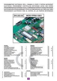
Terminal board connections31 Outer conductor for radio receiver antenna7 CMN common for all inputs and outputsNote (1) The total of the 2 external device outputs must not exceed 10 W.8 ELS electric lock output (fed continuously) 12 Vdc - 15 W.9-10 LC-CH2 potential free contact for the activation of the courtesy lightAll unused NC contacts must be jumped and consequently the(separate power supply Vmax = 30 Vac/dc: Imax = 1A) or the secondsecurity device test must also be deactivated (FTCI , FTCS - Dip 7 and Dipradio channel. Selection is carried out using jumper "J5".8 "OFF") . If you want to activate the FTCI, FTCS test both the transmission11 CMN common for all inputs and outputsand receiver parts of the security devices must be connected to the binding12 LP 24 Vdc 25 W output for warning lightspost marked "CTRL 30 Vdc". If the test is active there will be a 1 secondintermittent activation (50%), 12,5 W continuous activationdelay between the command transmission and movement of the gate/s.13 LS 24 Vdc 3 W output for an indicator light14 CMN common for all inputs and outputsSwitch on the power and make sure that the indicator LEDs are in the followingcondition.(1)15 30 Vdc controlled output, powering external loads16 CMN common for all inputs and outputs- L1 Power on ON17 30 Vdc output, powering external loads (1)- L2 Battery charging OFF18 CMN common for all inputs and outputs.(2)19 TA (NO contact) opening button input- L3 Wrong battery connection OFF (3)20 TC (NO contact) closing button input- L4 Transmitter code programming indicator OFF21 TAL (NO contact) limited opening button input- L5 Indicator for the blocking button "TB" ON (4)22 TD (NO contact) dynamic button inputAll rights reserved. Unauthorised copying or use of the information contained in this document is punishable by law23 CMN common for all inputs and outputs24 TB (NC contact) stop button input (The opening of this contact interruptsthe cycle until a new movement command is given).25 FTCS (NC contact) Safety and control devices in input. (stop photoelectriccells). The opening of this contact will block all movement, untilthe obstruction has been removed and the pause time has elapsed, dueto the safety device cutting in, the door will then continue moving in theclosing direction (only with automatic reclosing enabled).26 FTCI (NC contact) Safety and control devices in input (photocells invertthe travel direction when an obstruction is detected). Opening this contactwill provoke a travel direction inversion during closure due to the cuttingin of the safety device.27 EMRG2 (NO) emergency manoeuvre input 228 EMRG1 (NO) emergency manoeuvre input 129 CMN common for the emergency buttons30 Inner conductor for radio receiver antenna (if an external antenna isfitted use a coaxial type cable RG58 with an impedance of 50Ω).10J1L3J2F34A10F24A4AF4L2L13031J3- L6 Indicator for the inverting photoelectric cells "FTCI" ON (4)- L7 Indicator for the stop photoelectric cells "FTCS" ON (4)- L8 Indicator for the opening button "TA" OFF- L9 Indicator for the closing button "TC" OFF- L10 Indicator for the limited opening button "TAL" OFF- L11 Indicator for the sequential command "TD/CH1" OFFNote : This LED is "ON" when the battery is charging.(2)Note : If this LED is "ON" invert the battery power cables immediately.(3)Note : Check that the activation of the safety devices switches the corresponding(4)LEDs off.(4)If the green power on LED "L1" doesn't light up check the condition of thefuses and the power cable connection at the transformer primary.If one or more of the safety LEDs do not light up check the contacts of therelative security devices and check that the unused safety device contactshave been bridged.MMJ4R1L6L5L8B1L10CS 1218 DC0355P110Collegamento motori/encoder a 4 filiConnecting motor/4-wire encoderBranchement moteur/encodeur à 4 filsAnschluss der Motor/Encoder mit 4 DrähtenConexionado motores/encoder de 4 conductoresCOLORE COLOUR CODE COLORATIONCABLAGGI CODE DES CÂBLAGESBl Blu Blue BleuGr Verde Green VertGy Grigio Grey GrisYw Giallo Yellow JauneKABELFARBEN COLORACIÓNCABLEADOSBl Blau AzulGr Grün VerdeGy Grau GrisYw Gelb AmarilloM14A10F1ENCODER 1Bl Gr Gy YwM2ENCODER 2Bl Gr Gy Yw1 2 3 4 5 6 1 2 3 4 5 64A4AF5TDRAPLPLPLSFTCITFTITFTSSAPELSCMNELS 12VDS1ON1 2 3 4 5 6 7 8 910LC/CH2L7 L9 L11D1P2CSERL4J5P3CMNLPLSCMNCTRL 30VdcCMNOUT 30VdcCMNTA (N.O)TC (N.O)TAL (N.O)TD (N.O)CMNTB (N.C) 27 28 29CMNEMRG 1EMRG 2FTCS (N.C)FTCI (N.C)7 8 9 10 11 12 13 14 15 16 17 18 19 20 21 22 23 24 25 261 2 31 2 3Pos.1 Pos.2B1 Signal buzzer "via radio" modeJ2 Transformer secondary protectionCSER Serial connection (only for diagnostics)J3 Enable transmitter memorisation via radioD1 Six-segment LED displayJ4 Radio channel selectionDS1 Selection dip-switchJ5 Binding posts 9, 10 selection (courtesy light/CH2 via radio)F1 10A blade fuse (5) (motor power protection)MM Transmitter code memory moduleF2 10A blade fuse (5) (motor protection during battery operation) P1 Programming button (PROG)F3 4A blade fuse (5) (24V circuit protection)P2 Transmitter code memorization button (MEMO)F4 4A blade fuse (5) (24V circuit protection during battery operation) P3 Transmitter code cancellation button (DEL)F5 4A blade fuse (5) (electric lock protection)R1 Radio frequency module, 433 MHz for S449 transmittersJ1 Battery connectionDrawing number : DC0388Note (5) : These are automotive type blade fuses (max. voltage 58 V)Description : Collegamenti scheda baseProduct Code :CC242ESBBS17CENTRALINA 2 MOTORI CC CON ENCODER