HC950 • HC950 SSP HC970 • HC970 SSP - Wagner
HC950 • HC950 SSP HC970 • HC970 SSP - Wagner
HC950 • HC950 SSP HC970 • HC970 SSP - Wagner
- No tags were found...

Create successful ePaper yourself
Turn your PDF publications into a flip-book with our unique Google optimized e-Paper software.
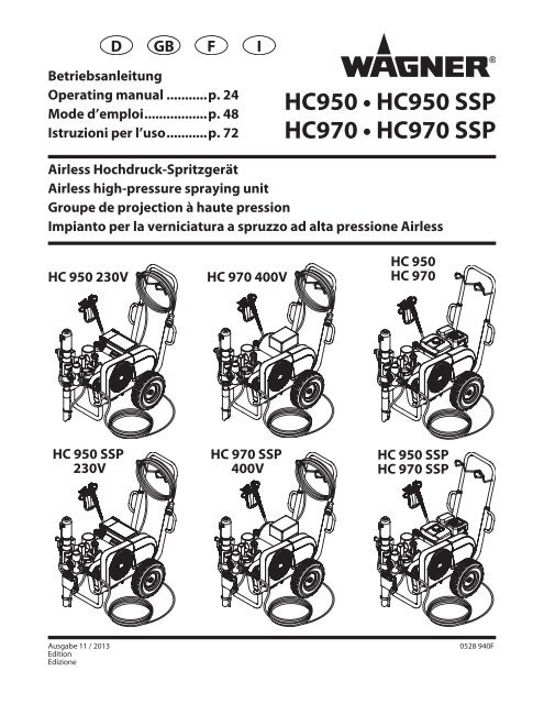
DGBFIBetriebsanleitungOperating manual............ p. 24Mode d’emploi.................. p. 48Istruzioni per l’uso............ p. 72<strong>HC950</strong> <strong>•</strong> <strong>HC950</strong> <strong>SSP</strong><strong>HC970</strong> <strong>•</strong> <strong>HC970</strong> <strong>SSP</strong>Airless Hochdruck-SpritzgerätAirless high-pressure spraying unitGroupe de projection à haute pressionImpianto per la verniciatura a spruzzo ad alta pressione AirlessHC 950 230VHC 970 400VHC 950HC 970HC 950 <strong>SSP</strong>230VHC 970 <strong>SSP</strong>400VHC 950 <strong>SSP</strong>HC 970 <strong>SSP</strong>Ausgabe 11 / 2013EditionEdizione0528 940F
Übersetzung der OriginalbetriebsanleitungDWarnung!Achtung: Verletzungsgefahr durch Injektion!Airless-Geräte entwickeln extrem hohe Spritzdrücke.123Niemals Finger, Hände oder andere Körperteile mit demSpritzstrahl in Berührung bringen!Nie die Spritzpistole auf sich, Personen und Tiere richten.Nie die Spritzpistole ohne Spritzstrahl-Berührungsschutzbenutzen.Behandeln Sie eine Spritzverletzung nicht als harmlose Schnittverletzung.Bei einer Hautverletzung durch Beschichtungsstoffoder Lösemittel sofort einen Arzt aufsuchen zur schnellen,fachkundigen Behandlung. Informieren Sie den Arzt über denverwendeten Beschichtungsstoff oder das Lösemittel.Vor jeder Inbetriebnahme sind gemäß Betriebsanleitung folgendePunkte zu beachten:1. Fehlerhafte Geräte dürfen nicht benutzt werden.2. <strong>Wagner</strong>-Spritzpistole sichern mit Sicherungshebel am Abzugsbügel.3. Erdung sicherstellen.4. Zulässigen Betriebsdruck von Hochdruckschlauch und Spritzpistoleüberprüfen.5. Alle Verbindungsteile auf Dichtheit prüfen.Anweisungen zur regelmäßigen Reinigung und Wartung desGerätes sind streng einzuhalten.Vor allen Arbeiten am Gerät und bei jeder Arbeitspause folgendeRegeln beachten:1. Spritzpistole und Hochdruckschlauch druckentlasten.2. <strong>Wagner</strong>-Spritzpistole sichern mit Sicherungshebel am Abzugsbügel.3. Gerät ausschalten.Achte auf Sicherheit!2 HC 950 <strong>•</strong> HC 970
InhaltDInhaltSeite1. Sicherheitsvorschriften für das Airless-Spritzen.................... 21.1 Erklärung der verwendeten Symbole............................................... 21.2 Elektrische Sicherheit.............................................................................. 31.3 Benzinmotoren-Betriebssicherheit.................................................... 31.4 Aufstellung in unebenem Gelände................................................... 42. Anwendungsübersicht........................................................................ 52.1 Einsatzgebiete........................................................................................... 52.2 Beschichtungsstoffe................................................................................ 53. Gerätebeschreibung............................................................................ 53.1 Airless-Verfahren...................................................................................... 53.2 Funktion des Gerätes.............................................................................. 53.3 Legende zum Erklärungsbild HC-Geräte mit Benzinmotor..... 63.4 Erklärungsbild HC-Geräte mit Benzinmotor................................... 63.5 Legende zum Erklärungsbild HC-Geräte mit Elektromotor...... 73.6 Erklärungsbild HC-Geräte mit Elektromotor.................................. 73.7 Technische Daten HC-Geräte mit Benzinmotor............................ 83.8 Technische Daten HC-Geräte mit Elektromotor........................... 93.9 Transport...................................................................................................103.10 Transport im Fahrzeug.........................................................................103.11 Krantransport...........................................................................................104. Inbetriebnahme....................................................................................114.1 Position der Materialförderpumpe ändern...................................114.2 Hochdruckschlauch, Spritzpistole und Trennöl..........................124.3 Benzinmotor (Geräte mit Benzinmotor)........................................124.4 Anschluss an das Stromnetz (Geräte mit Elektromotor)..........124.5 Bei ErstinbetriebnahmeReinigung von Konservierungsmittel.............................................124.6 Gerät mit Beschichtungsstoff in Betrieb nehmen......................135. Spritztechnik..........................................................................................136. Handhabung des Hochdruckschlauches..................................137. Arbeitsunterbrechung......................................................................138. Gerätereinigung (Außerbetriebnahme)...................................148.1 Gerätereinigung von außen...............................................................148.2 Hochdruckfilter reinigen.....................................................................148.3 Reinigung der Airless-Spritzpistole.................................................15Seite9. Hilfe bei Störungen.............................................................................169.1 Benzinmotor............................................................................................169.2 Elektromotor............................................................................................169.3 Hydraulikmotor.......................................................................................169.4 Materialförderpumpe...........................................................................1710. Wartung....................................................................................................1810.1 Allgemeine Wartung.............................................................................1810.2 Ölstandkontrolle im Hydrauliköltank..............................................1810.3 Öl- und Ölfilterwechsel bei der Hydraulikölpumpe...................1810.4 Hochdruckschlauch...............................................................................1811. Anhang......................................................................................................1911.1 Düsenauswahl.........................................................................................1911.2 Wartung und Reinigung von Airless-Hartmetall-Düsen...................................................................................1911.3 Spritzpistolen-Zubehör........................................................................1911.4 Airless-Düsen-Tabelle.................................................................... 20/2111.5 2Speed Tip Düsen-Tabelle..................................................................22<strong>Wagner</strong>-Servicenetz.........................................................................................23Zubehör und Ersatzteile.................................................................................96Zubehör für HC-Geräte I............................................................................. 96/97Zubehör für HC-Geräte II............................................................................ 98/99Ersatzteilliste Hauptbaugruppe.......................................................... 100/101Ersatzteilliste Wagen............................................................................... 102/103Ersatzteilliste Hydrauliksystem............................................................ 104/105Ersatzteilliste Hydraulikmotor............................................................. 106/107Ersatzteilliste Flüssigkeitsbereich ...................................................... 108/109Ersatzteilliste Schöpfkolben HC 950-<strong>SSP</strong> <strong>•</strong> HC 970-<strong>SSP</strong>.............. 110/111Ersatzteilliste Hochdruckfilter.............................................................. 112/113Ersatzteilliste Convertokit, Elektromotor (230V / 400V).......................114Ersatzteilliste Convertokit, Benzinmotor...................................................116Ersatzteilliste Keilriemenbaugruppe...........................................................117Ersatzteilliste Ablassschlauchbaugruppe..................................................118Schaltplan <strong>HC950</strong> <strong>•</strong> <strong>HC970</strong>...........................................................................119Prüfung des Gerätes.......................................................................................120Wichtiger Hinweis zur Produkthaftung................................................1203+2 Jahre Garantie Professional Finishing.........................................120HC 950 <strong>•</strong> HC 970 1
Sicherheitsvorschriften1. Sicherheitsvorschriften für das Airless-Spritzen1.1 Erklärung der verwendeten SymboleDiese Bedienanleitung enthält Informationen, die der Benutzer vorVerwendung des Geräts gründlich durcharbeiten muss. In Bereichen,die mit den folgenden Symbolen gekennzeichnet sind, besondersvorsichtig arbeiten und alle Sicherheitshinweise beachten.AchtungiDieses Symbol verweist auf eine potenzielleGefahr, die zum Tode oder zu schwerenVerletzungen führen kann. Hier finden Siewichtige Sicherheitsinformationen.Dieses Symbol weist auf eine potenzielle Gefahrfür Sie bzw. das Gerät hin. Unter diesem Symbolfinden Sie wichtige Informationen, wie SieSchäden an dem Gerät und Verletzungsgefahrvermeiden.InjektionsgefahrBrandgefahr durch Lösemittel und FarbdämpfeExplosionsgefahr durch Lösemittel, Farbdämpfeund ungeeignete MaterialienVerletzungsgefahr durch das Einatmen vonschädlichen DämpfenHinweise enthalten wichtige Informationen, diebeachtet werden sollten.GEFAHR: Verletzung durch Flüssigkeitenunter DruckEine unter hohem Druck stehende Flüssigkeit,wie sie von diesem Gerät erzeugt wird, kann dieHaut durchdringen und in das darunter liegendeBindegewebe eindringen und so zu schwerenVerletzungen und selbst zur Amputation führen.Behandeln Sie eine Spritzverletzung nichtals harmlose Schnittver-letzung. Bei einerHautverletzung durch Beschichtungsstoff oderLösemittel sofort einen Arzt aufsuchen zur schnellen,fachkundigen Behandlung. Informieren Sie denArzt über den verwendeten Beschichtungsstoff oderdas Lösemittel.VORSICHTSMASSNAHMEN:<strong>•</strong> NIEMALS die Spritzpistole auf Körperteile halten.<strong>•</strong> NIEMALS mit Körperteilen den Flüssigkeitsstrahl berühren.NIEMALS mit dem Körper eine Leckstelle im Druckschlauchberühren.<strong>•</strong> NIEMALS die Hand vor die Düse der Spritzpistole halten.Handschuhe stellen keinen sicheren Schutz vor Verletzungendurch injizierte Flüssigkeiten dar.<strong>•</strong> STETS den Auslöser der Spritzpistole verriegeln, die Pumpeausschalten und den Druck vollständig entspannen,bevor Wartungs- und Reinigungsarbeiten, Durchsichten,Düsenwechsel oder ähnliche Arbeiten durchgeführt werdenoder das Gerät unbeaufsichtigt gelassen wird. Auch nachdem Ausschalten des Motors steht das Gerät noch unterDruck. Das Ventil PRIME/SPRAY (Vorfüll-/Sprühventil) bzw.Ddas Druckentlastungsventil müssen in ihren Sollpositionenstehen, um den Systemdruck zu entspannen.<strong>•</strong> STETS den Düsenschutz aufsetzen, wenn Spritzarbeitendurchgeführt werden. Der Düsenschutz stellt einen gewissenSchutz dar, ist aber vor allem als Warnvorrichtung gedacht.<strong>•</strong> STETS die Spritzdüse entfernen, bevor das System gereinigtoder gespült wird.<strong>•</strong> NIEMALS eine Spritzpistole ohne funktionsfähigeAuslöserverriegelung und ohne Auslöserbügel verwenden.<strong>•</strong> Das gesamte Zubehör muss mindestens für den maximalenBetriebsdruckbereich des Spritzgeräts zugelassen sein. Dazugehören Spritzdüsen, Spritzpistolen, Verlängerungen undSchlauch.GEFAHR: HochdruckschlauchDurch Verschleiß, Knicken und nichtzweckentsprechende Verwendung können sichLeckstellen im Farbschlauch bilden. Durch eineLeckstelle kann Flüssigkeit in die Haut injiziertwerden. Vor Verwendung den Schlauch gründlichprüfen.VORSICHTSMASSNAHMEN:<strong>•</strong> Hochdruckschlauch vor jeder Benutzung gründlichüberprüfen.<strong>•</strong> Beschädigten Hochdruckschlauch sofort ersetzen.<strong>•</strong> Niemals defekten Hochdruckschlauch selbst reparieren!<strong>•</strong> Scharfes Biegen oder Knicken vermeiden, kleinsterBiegeradius etwa 20 cm.<strong>•</strong> Hochdruckschlauch nicht überfahren, sowie vor scharfenGegenständen und Kanten schützen.<strong>•</strong> Niemals am Hochdruckschlauch ziehen, um das Gerät zubewegen.<strong>•</strong> Hochdruckschlauch nicht verdrehen.<strong>•</strong> Hochdruckschlauch nicht in Lösemittel einlegen. Außenseitenur mit einem getränkten Tuch abwischen.<strong>•</strong> Hochdruckschlauch so verlegen, dass keine Stolpergefahrbesteht.iAus Gründen der Funktion, Sicherheitund Lebensdauer nur WAGNER Original-Hochdruckschläuche verwenden.GEFAHR: Explosions- und BrandgefahrLösungsmittel und Farbdämpfe können sichentzünden oder explodieren. Schwere Verletzungenund/oder Sachschäden können die Folge sein.VORSICHTSMASSNAHMEN:<strong>•</strong> Keine Materialien mit einem Flammpunkt unter 21 °C (70°F) verarbeiten. Der Flammpunkt ist die Temperatur, bei dereine Flüssigkeit so viele Dämpfe entwickelt, dass diese sichentzünden können.<strong>•</strong> Gerät nicht benutzen in Betriebsstätten, welche unter dieExplosionsschutz-Verordnung fallen.<strong>•</strong> Für guten Abzug und Zufuhr von Frischluft sorgen, damit sichim Spritzbereich keine entzündlichen Dämpfe sammeln.<strong>•</strong> Alle Zündquellen wie Funken durch elektrostatischeEntladung, Elektrogeräte, offene Flammen, Zündflammen,heiße Gegenstände und Funken durch Schließenund Trennen von Netzkabeln oder Betätigen vonArbeitsscheinwerferschaltern ausschließen.<strong>•</strong> Im Spritzbereich nicht rauchen.2 HC 950 <strong>•</strong> HC 970
<strong>•</strong> Das Spritzgerät in ausreichendem Abstand von dem zubespritzenden Gegenstand in einem gut belüfteten Bereichaufstellen (gegebenenfalls einen Verlängerungsschlauchbenutzen). Entzündliche Dämpfe sind oft schwerer alsLuft. Die Fläche über dem Boden muss besonders gutbelüftet werden. Die Pumpe enthält Teile, bei denen eineLichtbogenbildung nicht ausgeschlossen werden kann unddie durch Funken Dämpfe entzünden.<strong>•</strong> Die zu bespritzenden Objekte und die Ausrüstung imSpritzbereich müssen sorgfältig geerdet werden, um Funkendurch elektrostatische Entladungen zu vermeiden.<strong>•</strong> Nur leitfähige bzw. geerdete Hochdruckflüssigkeitsschläucheverwenden. Die Spritzpistole muss über dieSchlauchanschlüsse geerdet sein.<strong>•</strong> Das Netzkabel muss an einem Schutzkontaktstromkreisangeschlossen sein (nur für Elektrogeräte).<strong>•</strong> Zum Durchspülen des Gerätes immer in einen separatenMetallbehälter mit niedrigem Pumpendruck und entfernterSpritzdüse sprühen. Die Spritzpistole fest an die Wand desBehälters halten, um den Behälter zu erden und Funken durchelektrostatische Entladungen zu verhindern.<strong>•</strong> Die Warnhinweise und Vorschriften des Herstellers derLösungsmittel und Materialien einhalten. Beachten Siezum sicheren Gebrauch das Sicherheitsdatenblatt und dietechnischen Angaben des Anstrichmaterials.<strong>•</strong> Zum Spülen des Geräts immer mit einer möglichst niedrigenDruckeinstellung arbeiten.<strong>•</strong> Bei Gerätereinigung mit Lösemittel darf nicht in einenBehälter mit kleiner Öffnung (Spundloch) gespritztoder gepumpt werden. Gefahr durch Bildung einesexplosionsfähigen Gas-/Luftgemisches. Der Behälter mussgeerdet sein.Gefahr: Gefährliche DämpfeFarben, Lösungsmittel und andere Materialienkönnen beim Einatmen oder beim Kontakt mitdem Körper gesundheitsschädlich sein. DieDämpfe können schwere Übelkeit, Ohnmacht undVergiftungen verursachen.VORSICHTSMASSNAHMEN :<strong>•</strong> Bei Spritzarbeiten Atemschutz tragen. Alle mit derGesichtsmaske mitgelieferten Anleitungen durcharbeiten,damit die Gesichtsmaske auch den gewünschten Schutzbietet.<strong>•</strong> Dem Benutzer ist eine Atemschutzmaske zur Verfügung zustellen (Berufs-Genossenschaftliche Regeln „Regeln für denEinsatz von Atemschutzgeräten“ (BGR 190).<strong>•</strong> Arbeitsschutzbrille tragen.<strong>•</strong> Zum Schutz der Haut sind Schutzkleidung, Handschuhe undeventuell Hautschutzcreme erforderlich (BGR 197 “Benutzungvon Hautschutz”). Vorschriften der Hersteller beachten zu denBeschichtungsstoffen, Lösemittel und Reinigungsmittel beiAufbereitung, Verarbeitung und Gerätereinigung.DSicherheitsvorschriften<strong>•</strong> Nur vom Hersteller zugelassene Teile verwenden. BeiVerwendung von Teilen, die nicht die technischenMindestanforderungen erfüllen, trägt der Benutzer alleRisiken und die gesamte Haftung. Dies gilt auch für dieSicherheitsvorrichtungen der Pumpe.<strong>•</strong> IMMER die Hinweise des Herstellers zum sicheren Umgang mitFarben und Lösungsmitteln einhalten.<strong>•</strong> Verschüttete Materialien und Lösemitteln sofort aufwischen,um Rutschgefahr zu vermeiden.<strong>•</strong> Gehörschutz tragen. Dieses Gerät kann einen Schalldrucküber 85 dB(A) erzeugen.<strong>•</strong> Das Gerät niemals unbeaufsichtigt lassen. Kinder oder anderePersonen, die mit dem Betrieb des druckluftlosen Spritzgerätsnicht vertraut sind, von dem Gerät fern halten.<strong>•</strong> An windigen Tagen nicht im Freien spritzen.<strong>•</strong> Das Gerät inklusive aller Flüssigkeiten (z.B. Hydrauliköl)müssen umweltgerecht entsorgt werden.1.2 Elektrische SicherheitElektrogeräte müssen geerdet werden. Bei einem elektrischenKurzschluss reduziert die Erdung die Gefahr eines elektrischenSchlages, da der Fehlerstrom über den Schutzleiter abgeführtwird. Dieses Gerät ist mit einem Netzkabel versehen, das einenSchutzkontaktstecker besitzt. Anschluss an das Stromnetznur über einen besonderen Speisepunkt z. B. über eineFehlerstromschutzeinrichtung mit INF≤ 30 mA.GEFAHR — Arbeiten oder Reparaturen ander elektrischen Ausrüstung nur von einerElektrofachkraft durchführen lassen. Fürunsachgemäße Installation wird keine Haftungübernommen. Gerät ausschalten. Vor allenReparaturen – Netzstecker aus der Steckdose ziehen.Gerätereinigung: Kurzschlussgefahr durch eindringendes Wasserin die elektrische Ausrüstung.Gerät niemals mit Hochdruck- oderDampfhochdruckreiniger abspritzen.Arbeiten oder Reparaturen an der elektrischen Ausrüstung:Diese nur von einer Elektrofachkraft durchführen lassen. Fürunsachgemäße Installation wird keine Haftung übernommen.Gefahr: AllgemeinesKann schwere Personen- oder Sachschädenverursachen.VORSICHTSMASSNAHMEN :<strong>•</strong> Alle lokalen sowie im Land bzw. Bundesland geltendenVorschriften zum Brandschutz, zur Bedienung und Lüftungeinhalten.<strong>•</strong> Bei Betätigung des Auslösers zieht die Spritzpistole zur Seite.Diese Kraftwirkung der Spritzpistole ist besonders stark, wenndie Düse entfernt und bei der Pumpe hoher Druck eingestelltwurde. Bei der Reinigung mit abgeschraubter Düse daher denDruckreglerknopf auf den niedrigsten Druck einstellen.HC 950 <strong>•</strong> HC 970 3
SicherheitsvorschriftenD1.3 Benzinmotoren-BetriebssicherheitDas Spritzgerät stets außerhalb des Gebäudesim Freien aufstellen. Lösungsmittel von derAbgasanlage des Motors fern halten. DenKraftstofftank niemals bei heißem oder laufendemMotor betanken. Verschütteter Kraftstoff kann sichauf heißen Oberflächen entzünden. Die Pumpestets über ein Erdkabel mit einem geerdetenGegenstand verbinden. In der beiliegendenBedienungsanleitung des Motors finden Sie dievollständigen Sicherheitsinformationen.1. Benzinmotoren sind so gebaut, dass sie sicher undverlässlich funktionieren, wenn sie gemäss der Instruktionenbedient werden. Vor der Bedienung des Motors muss dasBesitzerhandbuch des Herstellers gelesen und verstandenwerden. Bei Unterlassung kann Personenverletzung oderSachschaden entstehen.2. Um Brandgefahr zu vermeiden und für ausreichendeBelüftung zu sorgen, muss der Motor mindestens 1 Meter vonGebäuden und anderen Maschinen entfernt sein wenn er inBetrieb ist. Keine brennbaren Gegenstände in der Nähe desMotors aufbewahren.3. Personen, die das Gerät nicht bedienen, dürfen denBetriebsbereich nicht betreten, da die Möglichkeit bestehtVerbrennungen von heissen Motorenteilen oder Verletzungendurch Geräte, die zur Bedienung des Motors benutzt werden,zu erleiden.4. Seien Sie vertraut damit, wie Sie den Motor schnellabstellen können und wissen Sie Bescheid über alleBedienungselemente und deren Handhabung. Erlauben Sieniemandem, den Motor ohne sachgerechte Anleitung zubedienen.5. Benzin ist äusserst leicht entflammbar und unter bestimmtenBedingungen explosiv.6. Tanken Sie Benzin nur in einem gut durchlüfteten Bereichnach, nachdem der Motor abgestellt wurde. Rauchen Sie nichtund erlauben Sie keine Flammen oder Funken im Bereich inwelchem aufgetankt wird oder Benzin aufbewahrt wird.7. Überfüllen Sie den Benzintank nicht. Vergewissern Sie sichnach dem Auftanken, dass die Tankverschlusskappe richtigund sicher aufgeschraubt ist.8. Seien Sie darauf bedacht, beim Auftanken kein Benzin zuverschütten. Benzindämpfe oder verschüttetes Benzinkönnte sich entflammen. Falls Benzin verschüttet wurde,vergewissern Sie sich, dass der Bereich trocken ist, bevor Sieden Motor starten.9. Lassen Sie den Motor nie in einem geschlossenen oder engenBereich laufen. Abgase enthalten giftige Kohlenmonoxidgase;diesen ausgesetzt läuft man Gefahr das Bewusstsein zuverlieren und es kann sogar zum Tod führen.10. Der Auspuff wird sehr heiss während der Motor läuft undbleibt nach abstellen des Motors noch für eine Weile heiss.Seien Sie darauf Bedacht, den Auspuff nicht zu berühren,solange er noch heiss ist. Um schwere Verbrennungen oderFeuergefahr zu vermeiden, lassen Sie den Motor abkühlen,bevor Sie ihn transportieren oder in einem Innenraumaufbewahren.11. Transportieren Sie die Sprühanlage niemals mit Benzin imTank.1.4 Aufstellung in unebenem GeländeDie Vorderseite des Geräts muss nach unten zeigen, um Wegrutschenzu vermeiden.Benutzen Sie diese Anlage NICHT um Laugen oderSäuren zu spritzen.4 HC 950 <strong>•</strong> HC 970
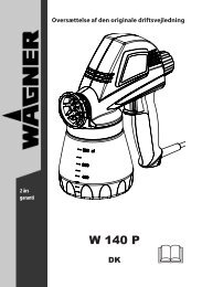
Anwendungsübersicht2. Anwendungsübersicht2.1 EinsatzgebieteGrundierung und Schlussbeschichtung von Großflächen,Versiegelung, Imprägnierung, Bausanierung, Fassadenschutzund Fassadenrenovierung, Rostschutz und Bautenschutz,Dachbeschichtung, Dachabdichtung, Betonsanierung, sowieschwerer Korrosionsschutz.Spritzobjekt-BeispieleGroßbaustellen, Tiefbau, Kühltürme, Brücken, Kläran lagen undFlachdächer.2.2 BeschichtungsstoffeVerarbeitbare BeschichtungsstoffeiAchten Sie auf Airless-Qualität bei den zuverarbeitenden Beschichtungsstoffen.Latexfarben, Dispersionsfarben, Flammschutz- undDickschichtmaterialien, Zinkstaub- und Eisenglimmerfarben,Airless-Spritzspachtel, spritzbare Kleber, Korrossionsschutz,Dickschichtmaterialien und bitumenähnliche Beschichtungsstoffe.Die Verarbeitung anderer Beschichtungsstoffe ist nur mitZustimmung der Firma WAGNER zulässig.HC 950-<strong>SSP</strong>Mit geeignetem Zubehör insbesondere zur Verarbeitung von Airless-Spritzspachtel (Objektgröße: 200-800 m2).HC 970-<strong>SSP</strong>Besonders geeignet zur Verarbeitung von Airless-Spritzspachtel(Objektgröße: über 800 m2).FilterungTrotz Hochdruckfilter ist eine Filterung des Beschichtungsstoffes imallgemeinen zu empfehlen (außer bei Spritzspachtel).Beschichtungsstoff vor Arbeitsbeginn gut umrühren.D3. GerätebeschreibungGerätebeschreibung3.1 Airless VerfahrenHauptanwendungsgebiete sind dicke Schichten von höherviskosemBeschichtungsstoff bei großen Flächen und hohem Materialeinsatz.Eine Kolbenpumpe saugt den Beschichtungsstoff an und fördertihn unter Druck zur Düse. Bei einem Druck bis max. 250 bar (25MPa) durch die Düse gepresst, zerstäubt der Beschichtungsstoff.Dieser hohe Druck bewirkt eine mikrofeine Zerstäubung desBeschichtungsstoffes.Da in diesem System keine Luft verwendet wird, bezeichnet mandieses Verfahren als AIRLESS-Verfahren (luftlos).Diese Art zu spritzen bringt die Vorteile von feinster Zerstäubung,nebelarmer Betriebsweise und glatter, blasenfreier Oberfläche.Neben diesen Vorteilen sind die Arbeits geschwindigkeit und diegroße Handlichkeit zu nennen.3.2 Funktion des GerätesZum besseren Verständnis der Funktion kurz den technischenAufbau.WAGNER HC 950 <strong>•</strong> 970 sind mit einem Benzin- oder Elektromotorangetriebene Hochdruckspritzgeräte.Der Benzinmotor oder Elektromotor (Abb. 2, Pos. 1) treibt über denKeilriemen unter der Riemenabdeckung (2) die Hydraulikpumpe (3)an. Hydrauliköl fließt zum Hydraulikmotor (4) und bewegt dann denKolben in der Materialförderpumpe (5) auf und ab.Bei den Geräten HC 950-<strong>SSP</strong> und HC 970-<strong>SSP</strong> bewegt der Kolben inder Materialförderpumpe einen Schöpfkolben (6). Der Schöpfkolbenfördert höchstvis kose Beschichtungsstoffe.Durch die Aufwärtsbewegung des Kolbens öffnet das Einlassventilselbstständig. Bei der Abwärtsbewegung des Kolbens öffnet dasAuslassventil.Der Beschichtungsstoff strömt unter hohem Druck durch denHochdruckschlauch zur Spritzpistole. Bei Austritt aus der Düsezerstäubt der Beschichtungsstoff.Das Druckregelventil (7) regelt die Fördermenge und denBetriebsdruck des Beschichtungsstoffs.iAchtung: Beim Aufrühren mit motorgetriebenenRührwerken darauf achten,dass keine Luftblaseneingerührt werden. Luftblasen stören beim Spritzen,können sogar zur Betriebsunterbrechung führen.ViskositätMit den Geräten ist es möglich, hochviskose Beschichtungsstoffe zuverarbeiten.Lassen sich hochviskose Beschichtungsstoffe nicht ansaugen, so istnach Herstellerangabe zu verdünnen.4731Zweikomponenten-BeschichtungsstoffDie entsprechende Verarbeitungszeit ist genau einzuhalten.Innerhalb dieser Zeit das Gerät sorgfältig mit dem entsprechendenReinigungsmittel durchspülen und reinigen.5Beschichtungsstoffe mit scharfkantigen ZusatzstoffenDiese üben auf Ventile, Hochdruckschlauch, Spritzpistole und Düseeine stark verschleißende Wirkung aus. Die Lebensdauer dieser Teilekann sich dadurch erheblich verkürzen.62HC 950 <strong>•</strong> HC 970 5
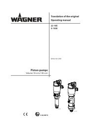
Allgemeine Beschreibung3.3 Legende zum Erklärungsbild HC-Geräte mit BenzinmotorD1 Spritzpistole2 Hochdruckschlauch3 Benzinmotor4 Deichsel ausziehbar5 Keilriemen unter der Riemenabdeckung6 Rücklaufschlauch7 Ansaugrohr8 Hochdruckfilter9 Materialförderpumpe — HC 950, HC 97010 Materialförderpumpe — HC 950-<strong>SSP</strong>, HC 970-<strong>SSP</strong>11 Manometer12 Einfüllöffnung für Trennöl (Trennöl verhindert erhöhtenVerschleiß der Packungen)13 Kugelhahn Hebelstellung waagrecht –Hydraulikmotor ausgeschaltetHebelstellung senkrecht –Hydraulikmotor eingeschaltet14 Handgriff zum Schwenken der Materialförderpumpe15 Hydraulikmotor16 EntlastungsventilhandgriffNach links drehen Zirkulation kNach rechts drehen Spritzen p17 Hydraulikölpumpe18 Druckregulierknopf19 Ölmessstab3.4 Erklärungsbild HC-Geräte mit Benzinmotor14231513121015141312119817 19181677656 HC 950 <strong>•</strong> HC 970
3.5 Legende zum Erklärungsbild HC-Geräte mit ElektromotorDAllgemeine Beschreibung1 Spritzpistole2 Hochdruckschlauch3 Elektromotor4 EIN/AUS-Schalter HC 950, HC 950-<strong>SSP</strong>5 Kontrollleuchte zeigt Betriebsbereitschaft anHC 950, HC 950-<strong>SSP</strong>6 Geräteanschlussleitung7 Deichsel ausziehbar8 Kontrollleuchte zeigt Betriebsbereitschaft anHC 970, HC 970-<strong>SSP</strong>9 EIN/AUS-Schalter (400 V) HC 970, HC 970-<strong>SSP</strong>10 Keilriemen unter der Riemenabdeckung11 Rücklaufschlauch12 Ansaugrohr13 Hochdruckfilter14 Materialförderpumpe — HC 950, HC 97015 Materialförderpumpe — HC 950-<strong>SSP</strong>, HC 970-<strong>SSP</strong>16 Manometer17 Einfüllöffnung für Trennöl (Trennöl verhindert erhöhtenVerschleiß der Packungen)18 Kugelhahn Hebelstellung waagrecht –Hydraulikmotor ausgeschaltetHebelstellung senkrecht –Hydraulikmotor eingeschaltet19 Handgriff zum Schwenken der Materialförderpumpe20 Hydraulikmotor21 EntlastungsventilhandgriffNach links drehen Zirkulation kNach rechts drehen Spritzen p22 Hydraulikölpumpe23 Druckregulierknopf24 Ölmessstab3.6 Erklärungsbild HC-Geräte mit Elektromotor1724 5620201922 24232138 9181817171615141312121110HC 950 <strong>•</strong> HC 970 7
Gerätebeschreibung3.7 Technische Daten HC-Geräte mit BenzinmotorDHC 950(0528500)HC 950-<strong>SSP</strong>(0528502)HC 970(0528508)HC 970-<strong>SSP</strong>(0528506)Benzinmotor, Leistung4,1 kW: R R6 kW: R Rmax. Betriebsdruck25 MPa (250 bar): R R R Rmax. Fördermenge8 l/min: R R12 l/min: R RFördermenge bei 120 bar (12 MPa) mit Wasser7,6 l/min: R R11 l/min: R Rmax. Düsengröße mit einer Spritzpistole0,052 inch (Zoll) – 1,30 mm: R R0,056 inch (Zoll) – 1,42 mm: R Rmax. Temperatur des Beschichtungsstoffs43° C: R R R Rmax. Viskosität50.000 mPa·s: R R65.000 mPa·s: R RFiltereinsatz (Standardausführung)0 Maschen: R R R RGewicht:76 kg R R88 kg R RHydrauliköl-Füllmenge4,7 l ISO 32: R R R Rmax. Reifendruck0,2 MPa (2 bar): R R R RSpezial-HochdruckschlauchDN 10 mm, 15 m, Anschlussgewinde NPSM 3/8:RDN 13 mm, 15 m, Anschlussgewinde NPSM 1/2: R R RSchlauchpeitscheDN 10 mm, 2,5 m, Anschlussgewinde NPSM 3/8: R R RAbmessungen L x H x B1185 x 955 x 655 mm: R R1200 x 955 x 655 mm: R Rmax. Schalldruckpegel:92 dB (A)* R R98 dB (A)* R R* Messort: Abstand 1 m seitlich vom Gerät und 1,60 m über schallhartem Boden, 12 MPa (120 bar) Betriebsdruck.8 HC 950 <strong>•</strong> HC 970
3.8 Technische Daten HC-Geräte mit ElektromotorDGerätebeschreibungHC 950(0528501)HC 950-<strong>SSP</strong>(0528503)HC 970(0528509)HC 970-<strong>SSP</strong>(0528507)Spannung230 V~, 50 Hz: R R400 V, 50 Hz, V3~: R RAbsicherung16 A: R R R RGeräteanschlussleitung3 x 2.5 mm 2 – 6 m: R R5 x 2.5 mm 2 – 6 m: R RAufnahmeleistung3,6 kW: R R5,5 kW: R Rmax. Betriebsdruck25 MPa (250 bar): R R R Rmax. Fördermenge6,6 l/min: R R10 l/min: R RFördermenge bei 120 bar (12 MPa) mit Wasser5,2 l/min: R R10 l/min: R Rmax. Düsengröße mit einer Spritzpistole0,052 inch (Zoll) – 1,30 mm: R R0,056 inch (Zoll) – 1,42 mm: R Rmax. Temperatur des Beschichtungsstoffs43° C: R R R Rmax. Viskosität50.000 mPa·s: R R65.000 mPa·s: R RFiltereinsatz (Standardausführung)0 Maschen: R R R RGewicht:83 kg R84,5 kg R100 kg R103 kg RHydrauliköl-Füllmenge4,7 l ISO 32: R R R Rmax. Reifendruck0,2 MPa (2 bar): R R R RSpezial-HochdruckschlauchDN 10 mm, 15 m, Anschlussgewinde NPSM 3/8:RDN 13 mm, 15 m, Anschlussgewinde NPSM 1/2: R R RSchlauchpeitscheDN 10 mm, 2,5 m, Anschlussgewinde NPSM 3/8: R R RAbmessungen L x H x B1185 x 955 x 655 mm: R R1200 x 955 x 655 mm: R Rmax. Schalldruckpegel:80 dB (A)* R R88 dB (A)* R R* Messort: Abstand 1 m seitlich vom Gerät und 1,60 m über schallhartem Boden, 12 MPa (120 bar) Betriebsdruck.HC 950 <strong>•</strong> HC 970 9
GerätebeschreibungBetriebstemperaturDieses Gerät funktioniert einwandfrei in seiner für ihn vorgesehenRaumtemperatur zwischen +10°C und +40°C.Relative FeuchtigkeitDas Gerät funktioniert in einem Umfeld mit einer relativenFeuchtigkeit von 50%, bei +40°C einwandfrei. Eine höhere relativeFeuchtigkeit stellt bei niedrigeren Temperaturen kein Problem dar.Der Käufer des Geräts muss Maßnahmen ergreifen, um dieschädigenden Auswirkungen der gelegentlichen Kondensation zuvermeiden.HöheDieses Gerät funktioniert in einer Höhe von bis zu 2100m über n.n.einwandfrei.Transport und AufbewahrungDieses Gerät hält Transport- bzw. Aufbewahrungstemperaturen von-25°C bis + 55°C, kurzzeitig auch bis zu +70°C, stand bzw. ist dagegengeschützt.Es wurde so verpackt, dass es Beschädigungen durch dieAuswirkungen von normaler Feuchtigkeit, Erschütterungen undStößen standhält.D1233.9 TransportAchtungBeim Auf- oder Abladen, nicht an der Deichselhalten.Gerät ist sehr schwer. Muss von drei Personengetragen werden.Gerät schiebenDeichsel (Abb. 5, Pos. 1) bis zum Anschlag herausziehen. Deichseleinfahren – Druckknöpfe (2) an den Holmen eindrücken, dannDeichsel einfahren.3.11 KrantransportAnhängepunkte für die Bänder oder Seile, siehe Abbildung 7.1223.10 Transport im FahrzeugDrücken Sie den Arretierstift (Abb. 6, Pos. 1) der Schwenkeinrichtung(2) und schwenken Sie die Materialförderpumpe (3) in einewaagrechte Position. Darauf achten, dass der Arretierstift einrastet.Hochdruckschlauch über die Aufhängung an der Deichsel aufrollen.Gerät mit geeignetem Befestigungsmittel sichern.10 HC 950 <strong>•</strong> HC 970
4. Inbetriebnahme4.1 Position der Materialförderpumpe ändernDInbetriebnahme2. Arbeitsposition I (Abb. 10)Materialförderpumpe in senkrechte Position schwenken, ermöglichtdie Materialförderpumpe in den Beschichtungsstoff-Behältereinzutauchen.Quetschgefahr für Finger und Füße! Vorsicht beimSchwenken der Materialförderpumpe.1. Handgriff (Abb. 8, Pos. 1) mit der einen Hand greifen.2. Mit der anderen Hand den Arretierstift (2) drücken.3. Materialförderpumpe je nach gewünschter Position nachunten oder oben schwenken, bis der Arretierstift (2) in derneuen Position einrastet.213. Arbeitsposition II (Abb. 11)Materialförderpumpe in schräge (45°) Position schwenken, beiEinsatz des Container Ansaugsystems (Zubehör). In dieser Position istFreiraum unter der Materialförderpumpe.1. Transportposition (Abb. 9)Transport vom Gerät nur in horizontaler Position derMaterialförderpumpe vornehmen.Materialförderpumpe in horizontale Position schwenken, ermöglichtauch die Materialförderpumpe aus dem Beschichtungsstoff-Behälterzu entnehmen.Darauf achten, dass der Arretierstift einrastet.HC 950 <strong>•</strong> HC 970 11
Inbetriebnahme4.2 Hochdruckschlauch, Spritzpistole undTrennöl1. Hochdruckschlauch (Abb. 12, Pos. 1) am Schlauchanschluss (2)anschrauben.2. HC 950-<strong>SSP</strong> <strong>•</strong> HC 970 und HC 970-<strong>SSP</strong> Doppelstutzen (3) in denHochdruckschlauch einschrauben.Schlauchpeitsche (4) anschrauben.3. Übergangsstutzen (5) an die Spritzpistole (6) schrauben.4. Spritzspistole mit ausgewählter Düse je nach Ausführungam Hochdruckschlauch oder an der Schlauchpeitsche (4)anschrauben.5. Überwurfmuttern am Hochdruckschlauch und je nachAusführung auch an der Schlauchpeitsche fest anziehen,damit kein Beschichtungsstoff austritt.26514316. EasyGlide einfüllen (Abb. 13). Nur soviel einfüllen, dass keinTrennöl in den Beschichtungsstoff-Behälter tropft.AchtungEasyGlide verhindert erhöhten Verschleiss derPackungen.D4.3 Benzinmotor (Geräte mit Benzinmotor)1. Mitgeliefertes Motoröl einfüllen.Der Benzinmotor wird ohne Motoröl transportiert.Der Ölstandsmelder verhindert das Starten ohneausreichenden Ölstand.Ölsorte und Ölmenge, siehe Motoranleitung.2. Benzintank füllen.Angaben zum Benzin, siehe Motoranleitung.4.4 Anschluss an das Stromnetz (Geräte mitElektromotor)AchtungDer Anschluss muss über eine vorschriftsmäßiggeerdete Schutzkontakt-Steckdose erfolgen.Vor Anschluss an das Stromnetz darauf achten, dass dieNetzspannung übereinstimmt mit der Angabe auf demLeistungsschild am Gerät.Sobald der Netzstecker angeschlossen ist, leuchtet die grüneKontrollleuchte.4.5 Bei Erstinbetriebnahme Reinigung vonKonservierungsmittel1. Arretierstift (Abb. 14, Pos. 1) ziehen und Materialförderpumpein einen Behälter mit geeignetem Reinigungsmitteleinschwenken.2. Druckregulierknopf (2) an der Hydraulikpumpe nach linksdrehen (Druckverringerung) bis zum Anschlag.3. Entlastungsventilhandgriff (3) völlig nach links drehen (kZirkulation).4. Benzinmotor starten oder Elektromotor starten:a. Den Benzinmotor starten, siehe Motoranleitung.b. Den Elektromotor starten:<strong>•</strong> Bei HC 950, Schalter auf 1 (EIN) stellen.<strong>•</strong> Bei HC 970, Schalterknopf zuerst auf Y, dann auf ∆ (EIN) stellen.iDie Drehrichtung der Riemenscheibe muss dem Pfeil(4) auf der Riemenabdeckung entsprechen. Falls dieRiemenscheibe entgegen der Pfeilrichtung läuft:Gerät ausschalten O (AUS). Netzstecker aussteckenund mit einem Schraubendreher den Polwender (5)im Netzstecker um 180 Grad drehen. Netzsteckerwieder einstecken.5. Kugelhahn (6) an der Materialförderpumpe senkrecht stellen –Hydraulikmotor schaltet ein.Hydrauliköl fließt zum Hydraulikmotor der Materialförderpumpe.6. Druckregulierknopf (2) nach rechts drehen (Druck erhöhung),bis Reinigungsmittel aus dem Rücklaufschlauch austritt.7. Entlastungsventilhandgriff (3) völlig nach rechts drehen (pSpritzen).8. Abzugsbügel der Spritzpistole ziehen.9. Reinigungsmittel aus dem Gerät in einen offenenSammelbehälter spritzen.12 HC 950 <strong>•</strong> HC 970
InbetriebnahmeDArbeitsunterbrechung613245. SpritztechnikWährend des Spritzvorganges die Spritzpistole gleichmäßigführen. Bei Nichteinhaltung tritt ein unregelmäßiges Spritzbildauf. Die Spritzbewegung mit dem Arm ausführen und nicht mitdem Handgelenk. Ein paralleler Abstand von ca. 30 cm zwischenSpritzpistole und Spritz objekt einhalten. Die seitliche Abgrenzungdes Spritzstrahles soll nicht zu scharf sein. Der Spritzrand sollteallmählich auflockern, damit beim nächsten Durchgang leichtüberlappt werden kann. Spritzpistole immer parallel und im Winkelvon 90° zur Spritzfläche führen, so entsteht am wenigsten Farbnebel.iBeim Auftreten sehr scharfer Randzonen undStreifen im Spritzstrahl – Betriebsdruck erhöhenoder Beschichtungsstoff verdünnen.6. Handhabung des HochdruckschlauchesDas Gerät ist mit einem speziell für Kolbenpumpen geeignetenHochdruckschlauch ausgerüstet.<strong>HC970</strong>E<strong>HC970</strong>E-<strong>SSP</strong>4.6 Gerät mit Beschichtungsstoff in Betrieb nehmenSteht das Gerät auf nicht leitfähigem Untergrundz.B. Holzboden, dann das Gerät mit einemErdungskabel erden.1. Arretierstift (Abb. 14, Pos. 1) ziehen und Materialförderpumpein den Beschichtungsstoff-Behälter eintauchen.2. Druckregulierknopf (2) an der Hydraulikpumpe bis zumAnschlag nach links drehen (Druckverringerung).3. Entlastungsventilhandgriff (3) völlig nach links drehen (kZirkulation).4. Benzinmotor starten oder Elektromotor starten:a. Den Benzinmotor starten, siehe Motoranleitung.b. Den Elektromotor starten:<strong>•</strong> Bei HC 950, Schalter auf 1 (EIN) stellen.<strong>•</strong> Bei HC 970, Schalterknopf zuerst auf Y, dann auf ∆ (EIN) stellen.iDie Drehrichtung der Riemenscheibe muss dem Pfeil(4) auf der Riemenabdeckung entsprechen. Falls dieRiemenscheibe entgegen der Pfeilrichtung läuft:Gerät ausschalten O (AUS). Netzstecker aussteckenund mit einem Schraubendreher den Polwender (5)im Netzstecker um 180 Grad drehen. Netzsteckerwieder einstecken.5. Kugelhahn (6) an der Materialförderpumpe senkrecht stellen –Hydraulikmotor schaltet ein.Hydrauliköl fließt zum Hydraulikmotor derMaterialförderpumpe.6. Druckregulierknopf (2) nach rechts drehen (Druck erhöhung),bis Beschichtungsstoff aus dem Rücklaufschlauch austritt.7. Entlastungsventilhandgriff (3) völlig nach rechts drehen (pSpritzen).8. Abzugsbügel der Spritzpistole ziehen, dann den gewünschtenBetriebsdruck mit dem Druckregulierknopf (2) einstellen.9. Das Gerät ist spritzbereit.5Verletzungsgefahr durch undichten Hochdruckschlauch.Beschädigten Hochdruckschlauch sofortersetzen.Niemals defekten Hochdruckschlauch selbst reparieren!Der Hochdruckschlauch ist sorgsam zu behandeln. Scharfes Biegenoder Knicken vermeiden, kleinster Biegeradius etwa 20 cm.Hochdruckschlauch nicht überfahren, sowie vor scharfenGegenständen und Kanten schützen.Niemals am Hochdruckschlauch ziehen, um das Gerät zu bewegen.Darauf achten, dass der Hochdruckschlauch sich nicht verdreht.Durch Verwendung einer <strong>Wagner</strong> Spritzpistole mit Drehgelenk undeiner Schlauchtrommel kann dies verhindert werden.iFür die Handhabung des Hochdruckschlauches beider Arbeit am Gerüst hat sich als am Vorteilhaftestenerwiesen, den Schlauch stets an der Außenseite desGerüstes zu führen.Bei alten Hochdruckschläuchen steigt das Risikovon Beschädigungen. <strong>Wagner</strong> empfiehlt denHochdruckschlauch nach 6 Jahren auszutauschen.Aus Gründen der Funktion, Sicherheit undLebensdauer nur WAGNER Original-Hochdruckschläucheverwenden.7. Arbeitsunterbrechung1. Kugelhahn an der Materialförderpumpe schließen –Hebelstellung waagrecht.Hydrauliköl-Durchfluss zum Hydraulikmotor derMaterialförderpumpe ist unterbrochen.2. Entlastungsventilhandgriff (3) völlig nach links drehen (kZirkulation).3. Stellen Sie den Benzinmotor oder den Elektromotor ab.4. Abzugsbügel der Spritzpistole ziehen, um Hochdruckschlauchund Spritzpistole vom Druck zu entlasten.5. Spritzpistole sichern, siehe Betriebsanleitung der Spritzpistole.6. Falls eine Standarddüse gereinigt werden soll, siehe Seite 19,Punkt 11.2.Ist eine andere Düsenausführung montiert, dann nachentsprechender Betriebsanleitung vorgehen.7. Ansaugrohr im Beschichtungsstoff eingetaucht lassen oderdieses in ein entsprechendes Reinigungsmittel eintauchen.AchtungBeim Einsatz von schnelltrocknenden – oderZweikomponenten-Beschichtungsstoff, Gerätunbedingt innerhalb der Verarbeitungszeit mitgeeignetem Reinigungsmittel durchspülen.HC 950 <strong>•</strong> HC 970 13
Gerätereinigung (Außerbetriebnahme)8. Gerätereinigung (Außerbetriebnahme)Sauberkeit ist die sicherste Gewährleistung für einen störungsfreienBetrieb. Nach Beendigung der Spritzarbeiten Gerät reinigen. Aufkeinen Fall dürfen Beschichtungsstoffe im Gerät antrocknen undsich festsetzen. Das zur Reinigung verwendete Reinigungsmittel (nurmit einem Flammpunkt über 21° C) muss dem Beschichtungsstoffeentsprechen.<strong>•</strong> Spritzpistole sichern, siehe Betriebsanleitung derSpritzpistole.Düse reinigen und demontieren.Standarddüse siehe Seite 19, Punkt 11.2.Ist eine andere Düsenausführung montiert, dann nachentsprechender Betriebsanleitung vorgehen.1. Arretierstift ziehen und Materialförderpumpe aus demBeschichtungsstoff herausschwenken.2. Abzugsbügel an der Spritzpistole ziehen, um restlichenBeschichtungsstoff aus dem Ansaugrohr, Hochdruckschlauchund der Spritzpistole in einen offenen Behälter zu pumpen.D8.1 Gerätereinigung von außenAchtungGeräte mit Benzinmotor — Benzinmotor abstellenund abkühlen lassen.Geräte mit Elektromotor — Zuerst Netzstecker ausder Steckdose ziehen.Kurzschlussgefahr durch eindringendes Wasser indie elektrische Ausrüstung des Benzinmotors.Gerät niemals mit Hochdruck- oderDampfhochdruckreiniger abspritzen.Hochdruckschlauch nicht in Lösemittel einlegen.Außenseite nur mit einem getränkten Tuchabwischen.Gerät außen mit einem in geeignetem Reinigungsmittel getränktenTuch abwischen.AchtungBei lösemittelhaltigen Beschichtungsstoffen mussder Behälter geerdet werden.Vorsicht! Nicht in Behälter mit kleiner Öffnung(Spundloch) pumpen oder spritzen!Siehe Sicherheitsvorschriften.3. Arretierstift ziehen und Materialförderpumpe in einenBehälter mit geeignetem Reinigungsmittel eintauchen.4. Entlastungsventilhandgriff völlig nach links drehen (kZirkulation).5. Geeignetes Reinigungsmittel einige Minuten im Kreislaufpumpen.6. Entlastungsventilhandgriff völlig nach rechts drehen (pSpritzen).7. Restliches Reinigungsmittel in einen offenen Behälterpumpen, bis das Gerät leer ist.8. Entlastungsventilhandgriff völlig nach links drehen (kZirkulation).9. Kugelhahn an der Materialförderpumpe schließen –Hebelstellung waagrecht.10. Stellen Sie den Benzinmotor oder den Elektromotor ab.8.2 Hochdruckfilter reinigenFilterpatrone regelmäßig reinigen.Ein verschmutzter oder verstopfter Hochdruckfilter verursacht einschlechtes Spritzbild oder eine verstopfte Düse.Demontage1. Kugelhahn an der Materialförderpumpe schließen –Hebelstellung waagrecht.Der Hydrauliköl-Durchfluss zum Hydraulikmotor derMaterialförderpumpe ist unterbrochen.2. Entlastungsventilhandgriff völlig nach links drehen (kZirkulation).3. Stellen Sie den Benzinmotor oder den Elektromotor ab.4. Gehäusedeckel (Abb. 15, Pos. 1) abschrauben.5. Filterpatrone (3) aus dem Gehäuse (8) herausziehen.6. Mit entsprechendem Reinigungsmittel Druckfeder (2)und Filterpatrone (3) mit Kugel reinigen, Gehäuse (8) undGehäusedeckel (1) innen reinigen.7. Kugel in der Filterpatrone (3) auf Verschleißspuren prüfen,wenn notwendig Filterpatrone austauschen.8. Ist die Kugel in der Filterpatrone (3) stark verschlissen, dannauch O-Ring (6) und Ventilsitz (7) ausbauen und bei Bedarfaustauschen.9. O-Ring (6) nach Ausbau immer austauschen.10. Druckfeder (2) vom Gehäusedeckel (1) abziehen. Länge derDruckfeder messen, falls weniger als 19 mm, dann Druckfederaustauschen.Montage1. Ventilsitz (7) mit der Kugelsitzfläche nach oben in das Gehäuse(8) einlegen.2. O-Ring (6) in das Gehäuse (8) einlegen.3. Filterpatrone (3) einsetzen.4. Dünne Dichtung (5) auf den Gewindeabsatz am Gehäuse (8)auflegen.5. Dicke Dichtung (4) auf die dünne Dichtung (5) legen.6. Druckfeder (2) auf den Stift im Gehäusedeckel (1) aufschieben.14 HC 950 <strong>•</strong> HC 970
1234567DGerätereinigung (Außerbetriebnahme)8.3 Reinigung der Airless-Spritzpistole– Airless-Spritzpistole bei niedrigem Betriebsdruck mitgeeignetem Reinigungsmittel durchspülen.– Düse gründlich mit geeignetem Reinigungsmittel reinigen, sodass keine Beschichtungsstoffreste zurückbleiben.– Airless-Spritzpistole außen gründlich reinigen.Einsteckfilter in der Airless-Spritzpistole (Abb. 16)Demontage1. Schutzbügel (1) kräftig nach vorne ziehen.2. Griff (2) aus dem Pistolengehäuse schrauben. Einsteckfilter (3)herausziehen.3. Ist der Einsteckfilter verstopft oder defekt, ersetzen Sie ihn.Montage1. Einsteckfilter (3) mit dem längeren Konus in dasPistolengehäuse stecken.2. Griff (2) in das Pistolengehäuse einschrauben und anziehen.3. Schutzbügel (1) einrasten.8312HC 950 <strong>•</strong> HC 970 15
Hilfe bei Störungen9. Hilfe bei Störungen9.1 BenzinmotorDArt der StörungA. Benzinmotor läuft nicht an9.2 ElektromotorArt der StörungA. Gerät läuft nicht anB. HC 970: Kolbenstange in derMaterialförderpumpe läuft nicht aufund ab.Mögliche Ursache1. Kein Benzin vorhanden2. EIN/AUS-Schalter auf AUS3. Benzinhahn geschlossen4. Motorproblem5. Motor defekt6. Ölstand unzureichendMögliche Ursache1. Kontrollleuchte zeigt keineBetriebsbereitschaft an.Keine Spannung vorhanden2. Bei Überbelastung schaltet sich dasGerät automatisch ab.1. Drehrichtung des Elektromotorsfalsch.Maßnahme zur Behebung der Störung1. Benzintank füllen2. Schalter auf EIN3. Benzinhahn öffnen4. Siehe Motoranleitung5. Zu Honda-Servicestelle bringen6. Öl nachfüllenMaßnahme zur Behebung der Störung1. Spannungsversorgung prüfen.2. Nach 2 – 3 Minuten, Gerät wieder einschalten.1. Polwender im Netzstecker um 180 Grad drehen.9.3 HydraulikmotorArt der StörungA. Hydraulikmotor bleibt in der unterenStellung stehenB. Hydraulikmotor bleibt in der oberenStellung stehen.C. Niedriger Druck. Kolbenstangebewegt sich normal im Abwärtshub,der Aufwärtshub ist aber träge.Hydraulikmotor ist außen sehr heiß.D. Niedriger Druck. Beim Aufwärts- undAbwärtshub wird der Hydraulikmotoraußen sehr heiß.Mögliche Ursache1. Auslassventilsitz in derMaterialförderpumpe lose.2. Umschaltventil im Hydraulikmotorsitzt fest oder obere/untereSechskantmutter an der Ventilstangehat sich gelöst.1. Umschaltventil sitzt fest.2. Druckfeder auf der Ventilstange istgebrochen.3. Druckfederanschlag auf derVentilstange ist gebrochen.4. Luft im Hydraulikmotor.5. Luft in der Materialförderpumpe.1. Defekte Kolbendichtung imHydraulikmotor.2. Kolbenstange gebrochen.1. Mittlerer O-Ring am Umschaltventildefekt.2. Packungen in derMaterialförderpumpe verschlissen.Maßnahme zur Behebung der Störung1. Kugelhahn an der Materialförderpumpe – Hebelstellungsenkrecht. Verschlussschraube am Hydraulikmotoroben abschrauben. Umschaltventil im Hydraulikmotornach unten drücken. Verschlussschraube wiedermontieren. Gerät starten. Bewegt sich die Kolbenstangenach oben und bleibt wieder in der unteren Stellungstehen, ist die Ursache der lose Auslassventilsitz.2. Von <strong>Wagner</strong>-Service beheben lassen.1. Von <strong>Wagner</strong>-Service beheben lassen.2. Von <strong>Wagner</strong>-Service beheben lassen.3. Von <strong>Wagner</strong>-Service beheben lassen.4. Druckregulierknopf zurückdrehen.Entlüften bei niedrigem Druck während 5-10 MinutenDauerlauf. Materialförderpumpe nicht trocken laufenlassen.Kontrolle auf Undichtigkeiten:<strong>•</strong> Lose Anschlüsse am Hydrauliköltank.<strong>•</strong> Lose Anschlüsse an der Hydraulikölpumpe<strong>•</strong> Lose Hydraulikölschlauchanschlüsse<strong>•</strong> Zu niederer Ölstand im Hydrauliktank5. Kugelhahn an der Materialförderpumpe – Hebelstellungsenkrecht. Verschlussschraube am Hydraulikmotor obenabschrauben. Umschaltventil im Hydraulikmotor nachunten drücken. Verschlussschraube wieder montieren.Gerät starten. Vermeiden, dass die MaterialförderpumpeLuft ansaugt.1. Von <strong>Wagner</strong>-Service beheben lassen.2. Von <strong>Wagner</strong>-Service beheben lassen.1. Von <strong>Wagner</strong>-Service beheben lassen.2. Austauschen16 HC 950 <strong>•</strong> HC 970
DHilfe bei Störungen9.4 MaterialförderpumpeArt der StörungA. Beschichtungsstoff-Förderung nurim Aufwärtshub oder Kolbenstangebewegt sich langsam aufwärts undschnell abwärts.B. Beschichtungsstoff-Förderung nurim Abwärtshub oder Kolbenstangebewegt sich langsam abwärts undschnell aufwärtsC. Kolbenstange bewegt sich schnellauf und ab.D. Kolbenstange bewegt sich langsamauf und ab bei geschlossenerSpritzpistole.E. Nicht genügend Druck an derSpritzpistole.F. Kolbenstange stottert im AufwärtsoderAbwärtshub.Mögliche Ursache1. Einlassventil ist undicht durchVerunreinigung oder Verschleiß.2. Beschichtungsstoff hat zu hoheViskosität, um angesaugt zu werden.1. Auslassventil undicht.2. Untere Packung verschlissen.1. Ansaugrohr ragt über denFlüssigkeitsspiegel hinaus und saugtLuft an.2. Beschichtungsstoff hat zu hoheViskosität, um angesaugt zu werden.3. Kugel im Einlassventilgehäuse klebtfest.1. Lose Verbindungen2. Entlastungsventil ist nicht ganzgeschlossen3. Entlastungsventil verschlissen4. Untere Packung verschlissen.5. Kugel im Einlassventilgehäuse undKugel im Auslassventilsitz dichtetnicht ab.1. Düse verschlissen2. Filterpatrone im Hochdruckfilterverstopft.3. Hochdruckschlauch zu lang1. Lösungsmittel hat obere Packungaufquellen lassen.Maßnahme zur Behebung der Störung1. Einlassventilgehäuse reinigen und kontrollieren. Kugeleinsetzen und Wasser einfüllen, wenn undicht Kugelaustauschen.2. Entsprechend Herstellerangaben verdünnen.1. Auslassventilsitz ausbauen und kontrollieren. Kugeleinsetzen und Wasser einfüllen, wenn undicht Kugelaustauschen.2. Austauschen1. Beschichtungsstoff nachfüllen2. Beschichtungsstoff entsprechend Herstellerangabenverdünnen.Materialförderpumpe entlüften,Entlastungsventilhandgriff nach links drehen (kZirkulation).3. Einlassventilgehäuse ausbauen, Kugel und Ventilsitzreinigen.1. Alle Verbindungen zwischen Materialförderpumpe undSpritzpistole kontrollieren.2. Entlastungsventilhandgriff völlig nach rechts drehen (pSpritzen).3. Austauschen4. Helfen oben beschriebene Maßnahmen nicht, dannuntere Packung austauschen.5. Einlassventilgehäuse und Auslassventilsitz ausbauen.Kugeln und Ventilsitze reinigen.1. Austauschen2. Filterpatrone reinigen oder austauschen.3. Länge reduzieren.1. Obere Packung austauschen.HC 950 <strong>•</strong> HC 970 17
Wartung10. Wartung10.1 Allgemeine WartungDie Wartung des Gerätes soll einmal jährlich durch den <strong>Wagner</strong>-Service durchgeführt werden.1. Wartung Benzinmotor siehe Motoranleitung.2. Hochdruckschläuche auf Beschädigung prüfen.3. Einlass- und Auslassventil auf Verschleiss prüfen.4. Ölstand im Hydrauliköltank prüfen.10.2 Ölstandkontrolle im HydrauliköltankiÖlstand täglich kontrollieren.Gerät ausschalten A (AUS).Netzstecker aus der Steckdose ziehen.1. Ölmessstab (Abb. 17, Pos. 1) nach links drehen undÖlmessstab herausziehen.2. Der Ölstand soll zwischen der Markierung (siehe Pfeile) amÖlmessstab sichtbar sein.3. Falls notwendig Öl nachfüllen, Ölsorte siehe unter Ölwechsel,Kapitel 10.3.DGerät ausschalten A (AUS).Netzstecker aus der Steckdose ziehen.1. Stellen Sie den Benzinmotor oder den Elektromotor ab.2. Kugelhahn (Abb. 18, Pos. 1) an der Materialförderpumpe –Hebelstellung senkrecht.3. Schrauben an der Abdeckung (2) der Hydraulikölpumpeabschrauben und Abdeckung abnehmen.4. Ölmessstab (3) nach links drehen und herausziehen.5. Ölfilter (4) mit Bandschlüssel abschrauben und austauschen.6. Verschlussschraube (5) unter dem Hydrau lik öltankabschrauben. Altöl ablassen.7. Verschlussschraube wieder einschrauben.8. 4,7 Liter Hydrauliköl (ISO 32) einfüllen.iBeim Ölfüllvorgang kann Luft in dasHydrauliksystem gelangen. Deshalb ist ein Entlüftendes Systems notwendig.9. Zur automatischen Entlüftung des Hydrauliksystems Gerätmindestens 5 Minuten bei niedrigem Druck laufen lassen.11423max:min:510.3 Öl- und Ölfilterwechsel bei derHydraulikölpumpeÖl- und Ölfilterwechsel alle 12 Monate durchführen.UmweltgefährdungAltöl nicht in die Kanalisation oder Erdreich ablassen.Grundwasserverschmutzung ist strafbar. Altöl wirdbeim Kauf von Hydrauliköl zurückgenommen.10.4 HochdruckschlauchHochdruckschlauch optisch auf eventuell vorhandene Einschnitteoder Ausbeulungen, insbesondere am Übergang in die Armatur,prüfen. Überwurfmuttern müssen sich frei drehen lassen.iBei alten Hochdruckschläuchen steigt das Risikovon Beschädigungen. <strong>Wagner</strong> empfiehlt denHochdruckschlauch nach 6 Jahren auszutauschen.iÖlwechsel im betriebswarmen Zustand des Gerätesvornehmen.18 HC 950 <strong>•</strong> HC 970
11. AnhangDAnhang11.1 DüsenauswahlUm eine einwandfreie und rationelle Arbeitsweise zu erzielen, ist die Auswahl der Düse von großer Wichtigkeit.In vielen Fällen kann die richtige Düse nur über einen Spritzversuch ermittelt werden.Einige Regeln hierzu:Der Spritzstrahl muss gleichmäßig sein.Wenn Streifen im Spritzstrahl erscheinen, so ist der Spritzdruck zu gering oder die Viskosität des Beschichtungs-stoffes zu hoch.Abhilfe: Druck erhöhen oder Beschichtungsstoff verdünnen. Jede Pumpe leistet eine bestimmte Fördermenge im Verhältnis zur Düsengröße:Es gilt grundsätzlich: Große Düse = niedriger DruckKleine Düse = hoher DruckEs gibt ein großes Sortiment von Düsen mit verschiedenen Spritzwinkeln.11.2 Wartung und Reinigung von Airless Hartmetall-DüsenStandarddüsenIst eine andere Düsenausführung montiert, dann nach Herstellerangaben reinigen.Die Düse hat eine mit größter Präzision bearbeitete Bohrung. Um eine lange Lebensdauer zu erreichen ist eine schonende Behandlungerforderlich. Denken Sie daran, dass der Hartmetalleinsatz spröde ist! Düse niemals werfen oder mit scharfen metallenen Gegenständenbearbeiten.Folgende Punkte sind zu beachten, um die Düse sauber und einsatzbereit zu halten:1. Entlastungsventil öffnen, Ventilstellung PRIME (k Zirkulation).2. Gerät ausschalten.3. Düse von der Spritzpistole demontieren.4. Düse in ein entsprechendes Reinigungsmittel legen bis alle Beschichtungsstoffreste aufgelöst sind.5. Wenn Druckluft vorhanden ist, Düse ausblasen.6. Mit einem spitzen hölzernen Stab (Zahnstocher) eventuelle Reste entfernen.7. Die Düse unter Zuhilfenahme eines Vergrößerungsglases kontrollieren und falls erforderlich, Punkt 4 bis 6 wiederholen.11.3 Spritzpistolen-ZubehörFlachstrahl-Verstelldüsebis 250 bar (25 MPa)DüsenmarkierungBohrungmmSpritzbreite bei etwa 30 cmEntfernung vom SpritzobjektDruck 100 bar (10 MPa)VerwendungFlachstrahl-VerstelldüseBestell-Nr15 0,13 - 0,46 5 - 35 cm Lacke 0999 05720 0,18 - 0,48 5 - 50 cm Lacke, Füller 0999 05328 0,28 - 0,66 8 - 55 cm Lacke, Dispersionen 0999 05441 0,43 - 0,88 10 - 60 cm Lacke, DispersionenRostschutzfarben -0999 05549 0,53 - 1,37 10 - 40 cm Großflächen-anstriche 0999 056Berührungsschutzzur Flachstrahl-VerstelldüseBestell-Nr. 0097 294Düsenverlängerung mitschwenkbaremKniegelenk(ohne Düse)Länge: 100 cm Bestell-Nr. 0096 015Länge: 200 cm Bestell-Nr. 0096 016Länge: 300 cm Bestell-Nr. 0096 017Düsenverlängerung15 cm, F-Gewinde, Bestell-Nr. 0556 051 15 cm, G-Gewinde, Bestell-Nr. 0556 07430 cm, F-Gewinde, Bestell-Nr. 0556 052 30 cm, G-Gewinde, Bestell-Nr. 0556 07545 cm, F-Gewinde, Bestell-Nr. 0556 053 45 cm, G-Gewinde, Bestell-Nr. 0556 07660 cm, F-Gewinde, Bestell-Nr. 0556 054 60 cm, G-Gewinde, Bestell-Nr. 0556 077HC 950 <strong>•</strong> HC 970 19
Anhang11.4 Airless Düsen-TabelleD<strong>Wagner</strong>TradeTip 3 Düsebis 270 bar(27 MPa)ohne DüseF-Gewinde (11/16 - 16 UN)für <strong>Wagner</strong> SpritzpistolenBest.-Nr. 0289391ohne DüseG-Gewinde (7/8 - 14 UNF)für Graco/Titan SpritzpistolenBest.-Nr. 0289390iAlle Düsen in der untenstehenden Tabelle werdenzusammen mit dem passenden Pistolenfiltergeliefert.Anwendung Düsenmarkierung SpritzwinkelWasserverdünnbare und lösemittelhaltigeLacke und Lackfarben, Öle,TrennmittelKunstharzlackePVC-LackeLacke, VorlackeGrundlackeFüllerFüllerRostschutzfarbenRostschutzfarbenLatexfarbenDispersionenRostschutzfarbenLatexfarbenDispersionen107207307407109209309409509609111211311411511611113213313413513613813115215315415515615715815117217317417517617717817219319419519619719819919Flammschutz 22132142152162172182110°20°30°40°10°20°30°40°50°60°10°20°30°40°50°60°10°20°30°40°50°60°80°10°20°30°40°50°60°70°80°10°20°30°40°50°60°70°80°20°30°40°50°60°70°80°90°20°30°40°50°60°70°80°Bohrung Spritzbreite mm 1) Pistolenfilter Bestell-Nr.inch / mm0.007 / 0.180.007 / 0.180.007 / 0.180.007 / 0.180.009 / 0.230.009 / 0.230.009 / 0.230.009 / 0.230.009 / 0.230.009 / 0.230.011 / 0.280.011 / 0.280.011 / 0.280.011 / 0.280.011 / 0.280.011 / 0.280.013 / 0.330.013 / 0.330.013 / 0.330.013 / 0.330.013 / 0.330.013 / 0.330.013 / 0.330.015 / 0.380.015 / 0.380.015 / 0.380.015 / 0.380.015 / 0.380.015 / 0.380.015 / 0.380.015 / 0.380.017 / 0.430.017 / 0.430.017 / 0.430.017 / 0.430.017 / 0.430.017 / 0.430.017 / 0.430.017 / 0.430.019 / 0.480.019 / 0.480.019 / 0.480.019 / 0.480.019 / 0.480.019 / 0.480.019 / 0.480.019 / 0.480.021 / 0.530.021 / 0.530.021 / 0.530.021 / 0.530.021 / 0.530.021 / 0.530.021 / 0.53100120150190100120150190225270100120150190225270100120150190225270330100120150190225270300330100120150190225270300330120150190225270300330385120150190225270300330RotRotRotRotRotRotRotRotRotRotRotRotRotRotRotRotRotRotRotRotRotRotRotGelbGelbGelbGelbGelbGelbGelbGelbGelbGelbGelbGelbGelbGelbGelbGelbWeißWeißWeißWeißWeißWeißWeißWeißWeißWeißWeißWeißWeißWeißWeiß0553107055320705533070553407055310905532090553309055340905535090553609055311105532110553311055341105535110553611055311305532130553313055341305535130553613055381305531150553215055331505534150553515055361505537150553815055311705532170553317055341705535170553617055371705538170553219055331905534190553519055361905537190553819055391905532210553321055342105535210553621055372105538211)Spritzbreite bei etwa 30 cm Abstand zum Spritzobjekt und 100 bar (10 MPa) Druck mit Kunstharzlack 20 DIN-Sekunden.20 HC 950 <strong>•</strong> HC 970
DAnhangAnwendung Düsenmarkierung SpritzwinkelDachbeschichtung 223323423523623723823Dickschichtmaterialien,Korrosionsschutz,Spritzspachtel225325425525625725825227327427527627827229329429529629231331431531631731831233333433533633235335435535635735439539639Heavy Duty Applikationen 24344354364344554564545155165125245555565526146156166126346356566526746720°30°40°50°60°70°80°20°30°40°50°60°70°80°20°30°40°50°60°80°20°30°40°50°60°20°30°40°50°60°70°80°20°30°40°50°60°20°30°40°50°60°70°40°50°60°20°40°50°60°40°50°60°40°50°60°20°40°50°60°20°40°50°60°20°40°50°60°20°40°Bohrung Spritzbreite mm 1) Pistolenfilter Bestell-Nr.inch / mm0.023 / 0.580.023 / 0.580.023 / 0.580.023 / 0.580.023 / 0.580.023 / 0.580.023 / 0.580.025 / 0.640.025 / 0.640.025 / 0.640.025 / 0.640.025 / 0.640.025 / 0.640.025 / 0.640.027 / 0.690.027 / 0.690.027 / 0.690.027 / 0.690.027 / 0.690.027 / 0.690.029 / 0.750.029 / 0.750.029 / 0.750.029 / 0.750.029 / 0.750.031 / 0.790.031 / 0.790.031 / 0.790.031 / 0.790.031 / 0.790.031 / 0.790.031 / 0.790.033 / 0.830.033 / 0.830.033 / 0.830.033 / 0.830.033 / 0.830.035 / 0.900.035 / 0.900.035 / 0.900.035 / 0.900.035 / 0.900.035 / 0.900.039 / 0.990.039 / 0.990.039 / 0.990.043 / 1.100.043 / 1.100.043 / 1.100.043 / 1.100.045 / 1.140.045 / 1.140.045 / 1.140.051 / 1.300.051 / 1.300.051 / 1.300.052 / 1.320.055 / 1.400.055 / 1.400.055 / 1.400.061 / 1.550.061 / 1.550.061 / 1.550.061 / 1.550.063 / 1.600.063 / 1.600.065 / 1.650.065 / 1.650.067 / 1.700.067 / 1.70120150190225270300330120150190225270300330120150190225270330120150190225270120150190225270300330120150190225270120150190225270300190225270120190225270190225270190225270120190225270120190225270120190225270120190WeißWeißWeißWeißWeißWeißWeißWeißWeißWeißWeißWeißWeißWeißWeißWeißWeißWeißWeißWeißWeißWeißWeißWeißWeißWeißWeißWeißWeißWeißWeißWeißWeißWeißWeißWeißWeißWeißWeißWeißWeißWeißWeißWeißWeißWeißGrünGrünGrünGrünGrünGrünGrünGrünGrünGrünGrünGrünGrünGrünGrünGrünGrünGrünGrünGrünGrünGrünGrünGrün05532230553323055342305535230553623055372305538230553225055332505534250553525055362505537250553825055322705533270553427055352705536270553827055322905533290553429055352905536290553231055333105534310553531055363105537310553831055323305533330553433055353305536330553235055333505534350553535055363505537350553439055353905536390553243055344305535430553643055344505535450553645055345105535510553651055325205534550553555055365505532610553461055356105536610553263055346305535650553665055326705534671)Spritzbreite bei etwa 30 cm Abstand zum Spritzobjekt und 100 bar (10 MPa) Druck mit Kunstharzlack 20 DIN-Sekunden.HC 950 <strong>•</strong> HC 970 21
Anhang11.5 2Speed Tip Düsen-TabelleDDie innovative Wendedüse von WAGNER vereint zweiDüsenkerne in einer Düse.2 Speed Tip HalterungBest.-Nr. 0271065Düsen-TabelleObjektgrößeSmallMediumLargeX-LargeFarbmaterialienLack (L) Dispersionen (D) Spachtel (S)L10Düsen: 208 / 510Best.-Nr. 0271 042L20Düsen: 210 / 512Best.-Nr. 0271 043L30Düsen: 212 / 514Best.-Nr. 0271 044D5Düsen: 111 / 415Best.-Nr. 0271 062D7Düsen: 113 / 417Best.-Nr. 0271 063D10Düsen: 111 / 419Best.-Nr. 0271 045D20Düsen: 115 / 421Best.-Nr. 0271 046D30Düsen: 115 / 423Best.-Nr. 0271 047D40Düsen: 117 / 427Best.-Nr. 0271 048S5Düsen: 225 / 629Best.-Nr. 0271 064S10Düsen: 527 / 235Best.-Nr. 0271 049S20Düsen: 539 / 243Best.-Nr. 0271 050S30Düsen: 543 / 252Best.-Nr. 0271 051Empfohlener Pistolenfilter rot weiß -22 HC 950 <strong>•</strong> HC 970
BerlinJ. <strong>Wagner</strong> GmbHService-StützpunktFlottenstraße 28–4213407 BerlinTel. 0 30/ 41 10 93 86Telefax 0 30 / 41 10 93 87GrünstadtJ. <strong>Wagner</strong> GmbHService-StützpunktDieselstraße 167269 GrünstadtTel. 0 63 59/ 87 27 55 0Telefax 0 63 59/ 80 74 80RatingenJ. <strong>Wagner</strong> GmbHService-StützpunktSiemensstraße 6-1040885 RatingenTel. 0 21 02 / 3 10 37Telefax 0 21 02 / 3 43 95StuttgartJ. <strong>Wagner</strong> GmbHService-StützpunktIn der Steige 6/172564 NeckartenzlingenTel. 0 71 27 / 30 74Telefax 0 71 27 / 30 75MünchenJahnke GmbHHochstraße 782024 TaufkirchenTel. 0 89 /6 14 00 22Telefax 0 89 / 6 14 04 33email: info@airless.dewww.airless.deNürnbergGrimmer GmbHStarenweg 2891126 SchwabachTel. 0 91 22 / 7 94 73Telefax 0 91 22 / 7 94 75 0email: info@grimmer-sc.dewww.grimmer-sc.deMarkdorf – ZentraleJ. <strong>Wagner</strong> GmbHOtto-Lilienthal-Straße 1888677 MarkdorfPostfach 11 2088669 MarkdorfTel. 0 75 44 / 505-0Telefax 0 75 44 / 505-1200www.wagner-group.comKundenzentrumTel. 0 75 44 / 505-1664Telefax 0 75 44 / 505-1155email: kundenzentrum@wagner-group.comTechnischer ServiceTel. 0180/5 59 24 637(14 Cent/Min. aus dem deutschen Festnetz,Mobilfunk max. 42 Cent/Min)Heidersdorf in SachsenJ. <strong>Wagner</strong> GmbHService-StützpunktOlbernhauer Straße 1109526 HeidersdorfTel. 03 73 61 / 1 57 07Telefax 03 73 61 / 1 57 08<strong>Wagner</strong> Kontaktnetz Deutschland, im Internet zu finden unter: www.wagner-group.com/profiwww.wagner-group.comHC 950 <strong>•</strong> HC 970 23
Original Operating ManualGBWarning!Attention: Danger of injury by injection!Airless units develop extremely high spraying pressures.123Never put your fingers, hands or any other parts of the body intothe spray jet!Never point the spray gun at yourself, other persons or animals.Never use the spray gun without safety guard.Do not treat a spraying injury as a harmless cut. In case of injuryto the skin through coating materials or solvents, consult a doctorimmediately for quick and expert treatment. Inform the doctorabout the coating material or solvent used.The operating instructions state that the following points mustalways be observed before starting up:1. Faulty units must not be used.2. Secure WAGNER spray gun using the safety catch on the trigger.3. Ensure that the unit is properly earthed.4. Check allowable operating pressure of high-pressure hose andspray gun.5. Check all connections for leaks.The instructions regarding regular cleaning and maintenance ofthe unit must be strictly observed.Before any work is done on the unit or for every break in work thefollowing rules must be observed:1. Release the pressure from spray gun and hose.2. Secure the WAGNER spray gun using the safety catch on the trigger.3. Switch off unit.Be safety conscious!24 HC 950 <strong>•</strong> HC 970
ContentsGBContentsPage1. Safety regulations for Airless spraying.....................................261.1 Explanation of symbols used.............................................................261.2 Electrical safety........................................................................................271.3 Gasoline engine safety.........................................................................281.4 Setting up on uneven surfaces..........................................................282. General view of application............................................................292.1 Application...............................................................................................292.2 Coating materials...................................................................................293. Description of unit..............................................................................293.1 Airless process.........................................................................................293.2 Functioning of the unit........................................................................293.3 Illustration legend for gasoline HC units.......................................303.4 Illustration of gasoline HC units........................................................303.5 Illustration legend for electric HC units..........................................313.6 Illustration of electric HC units..........................................................313.7 Technical data for gasoline HC units...............................................323.8 Technical data for electric HC units.................................................333.9 Transport...................................................................................................343.10 Transport in vehicle...............................................................................343.11 Crane transport.......................................................................................344. Starting operation...............................................................................354.1 Changing the material feed pump position.................................354.2 High-pressure hose, spray gun and separating oil....................364.3 Gasoline engine (gas units only).......................................................364.4 Connection to the mains (electric units only)..............................364.5 Flushing preserving fluid during initial start-up.........................364.6 Taking the unit into operation with coating material..............375. Spraying technique............................................................................376. Handling the high-pressure hose................................................377. Interruption of work...........................................................................378. Cleaning the unit (shutting down)..............................................388.1 Cleaning the unit from the outside.................................................388.2 Cleaning the high-pressure filter......................................................388.3 Cleaning Airless spray gun..................................................................39Page9. Remedy in case of faults...................................................................409.1 Gasoline engine......................................................................................409.2 Electric motor..........................................................................................409.3 Hydraulic motor......................................................................................409.4 Material feed pump...............................................................................4110. Servicing...................................................................................................4210.1 General servicing....................................................................................4210.2 Checking the oil level in the hydraulic oil tank...........................4210.3 Oil and oil filter change of the hydraulic oil pump....................4210.4 High-pressure hose...............................................................................4211. Appendix..................................................................................................4311.1 Selection of tip........................................................................................4311.2 Servicing and cleaning of Airless hard-metal tips .....................4311.3 Spray gun accessories...........................................................................4311.4 Airless tip table................................................................................. 44/4511.5 2Speed Tip table.....................................................................................46Sales and service companies........................................................................47Accessories and spare parts.........................................................................96Accessories for HC units I........................................................................... 96/97Accessories for HC units II.......................................................................... 98/99Spare parts list for the main assembly.............................................. 100/101Spare parts list for the cart assembly................................................ 102/103Spare parts list for the hydraulic system.......................................... 104/105Spare parts list for the hydraulic motor........................................... 106/107Spare parts list for the fluid section................................................... 108/109Spare parts list for the shovel valveHC 950-<strong>SSP</strong> <strong>•</strong> HC 970-<strong>SSP</strong>....................................................................... 110/111Spare parts list for the high-pressure filter..................................... 112/113Spare parts list for electric convertokit (230V / 400V)...........................114Spare parts list for gas convertokit..............................................................116Spare parts list for belt guard assembly.....................................................117Spare parts list for bleed valve......................................................................118Electrical schematic <strong>HC950</strong> <strong>•</strong> <strong>HC970</strong>.......................................................119Important notes on product liability.....................................................1213+2 years guarantee for professional finishing ...............................121HC 950 <strong>•</strong> HC 970 25
Safety precautions1. Safety regulations for Airless spraying1.1 Explanation of symbols usedThis manual contains information that must be read and understoodbefore using the equipment. When you come to an area that has oneof the following symbols, pay particular attention and make certainto heed the safeguard.AttentionThis symbol indicates a potential hazard thatmay cause serious injury or loss of life. Importantsafety information will follow.This symbol indicates a potential hazard to youor to the equipment. Important information thattells how to prevent damage to the equipment orhow to avoid causes of minor injuries will follow.Danger of skin injectionDanger of fire from solvent and paint fumesDanger of explosion from solvent, paint fumesand incompatible materialsDanger of injury from inhalation of harmfulvaporsGB<strong>•</strong> All accessories must be rated at or above the maximumoperating pressure range of the sprayer. This includes spraytips, guns, extensions, and hose.HAZARD: High Pressure HoseThe paint hose can develop leaks from wear, kinkingand abuse. A leak can inject material into the skin.Inspect the hose before each use.PREVENTION:<strong>•</strong> High-pressure hoses must be checked thoroughly before theyare used.<strong>•</strong> Replace any damaged high-pressure hose immediately.<strong>•</strong> Never repair defective high-pressure hoses yourself!<strong>•</strong> Avoid sharp bends and folds: the smallest bending radius isabout 20 cm.<strong>•</strong> Do not drive over the high-pressure hose. Protect againstsharp objects and edges.<strong>•</strong> Never pull on the high-pressure hose to move the device.<strong>•</strong> Do not twist the high-pressure hose.<strong>•</strong> Do not put the high-pressure hose into solvents. Use only awet cloth to wipe down the outside of the hose.<strong>•</strong> Lay the high-pressure hose in such a way as to ensure that itcannot be tripped over.iOnly use WAGNER original-high-pressure hoses inorder to ensure functionality, safety and durability.iNotes give important information which shouldbe given special attention.HAZARD: EXPLOSION OR FIRESolvent and paint fumes can explode or ignite.Severe injury and/or property damage can occur.HAZARD: Injection injuryA high pressure stream produced by this equipmentcan pierce the skin and underlying tissues, leading toserious injury and possible amputation.Do not treat a spraying injury as a harmless cut. Incase of injury to the skin through coating materialsor solvents, consult a doctor immediately for quickand expert treatment. Inform the doctor about thecoating material or solvent used.PREVENTION:<strong>•</strong> NEVER aim the gun at any part of the body.<strong>•</strong> NEVER allow any part of the body to touch the fluid stream.DO NOT allow body to touch a leak in the fluid hose.<strong>•</strong> NEVER put your hand in front of the gun. Gloves will notprovide protection against an injection injury.<strong>•</strong> ALWAYS lock the gun trigger, shut the fluid pump off andrelease all pressure before servicing, cleaning the tip guard,changing tips, or leaving unattended. Pressure will not bereleased by turning off the engine. The PRIME/SPRAY valveor pressure bleed valve must be turned to their appropriatepositions to relieve system pressure.<strong>•</strong> ALWAYS keep tip guard in place while spraying. The tip guardprovides some protection but is mainly a warning device.<strong>•</strong> ALWAYS remove the spray tip before flushing or cleaning thesystem.<strong>•</strong> NEVER use a spray gun without a working trigger lock andtrigger guard in place.PREVENTION:<strong>•</strong> Do not use materials with a flashpoint below 21° C (70° F).Flashpoint is the temperature at which a fluid can produceenough vapors to ignite.<strong>•</strong> Do not use the unit in work places which are covered by theexplosion protection regulations.<strong>•</strong> Provide extensive exhaust and fresh air introduction tokeep the air within the spray area free from accumulation offlammable vapors.<strong>•</strong> Avoid all ignition sources such as static electricity sparks,electrical appliances, flames, pilot lights, hot objects, andsparks from connecting and disconnecting power cords orworking light switches.<strong>•</strong> Do not smoke in spray area.<strong>•</strong> Place sprayer sufficient distance from the spray object in awell ventilated area (add more hose if necessary). Flammablevapors are often heavier than air. Floor area must beextremely well ventilated. The pump contains arcing partsthat emit sparks and can ignite vapors.<strong>•</strong> The equipment and objects in and around the spray area mustbe properly grounded to prevent static sparks.<strong>•</strong> Use only conductive or earthed high pressure fluid hose. Gunmust be earthed through hose connections.<strong>•</strong> Power cord must be connected to a grounded circuit (electricunits only).<strong>•</strong> Always flush unit into separate metal container, at low pumppressure, with spray tip removed. Hold gun firmly against sideof container to ground container and prevent static sparks.26 HC 950 <strong>•</strong> HC 970
<strong>•</strong> Follow material and solvent manufacturer’s warnings andinstructions. Be familiar with the coating material’s MSDSsheet and technical information to ensure safe use.<strong>•</strong> Use lowest possible pressure to flush equipment.<strong>•</strong> When cleaning the unit with solvents, the solvent shouldnever be sprayed or pumped back into a container with asmall opening (bunghole). An explosive gas/air mixture canarise. The container must be earthed.HAZARD: HAZARDOUS VAPORSPaints, solvents, and other materials can be harmfulif inhaled or come in contact with body. Vapors cancause severe nausea, fainting, or poisoning.PREVENTION:<strong>•</strong> Wear respiratory protection when spraying. Read allinstructions supplied with the mask to be sure it will providethe necessary protection.<strong>•</strong> All local regulations regarding protection against hazardousvapors must be observed.<strong>•</strong> Wear protective eyewear.<strong>•</strong> Protective clothing, gloves and possibly skin protection creamare necessary for the protection of the skin. Observe theregulations of the manufacturer concerning coating materials,solvents and cleaning agents in preparation, processing andcleaning units.GBSafety precautions1.2 Electric SafetyElectric models must be earthed. In the event of an electrical shortcircuit, earthing reduces the risk of electric shock by providing anescape wire for the electric current. This product is equipped witha cord having an earthing wire with an appropriate earthing plug.Connection to the mains only through a special feed point, e.g.through an error protection insallation with INF < 30 mA.DANGER — Work or repairs at the electricalequipment may only be carried out by a skilledelectrician. No liability is assumed for incorrectinstallation. Switch the unit off. Before all repairwork, unplug the power plug from the outlet.Danger of short-circuits caused by water ingressing into the electricalequipment. Never spray down the unit with high-pressure or highpressuresteam cleaners.Work or repairs at the electrical equipment:These may only be carried out by a skilled electrician. No liability isassumed for incorrect installation.HAZARD: GENERALThis product can cause severe injury or propertydamage.PREVENTION:<strong>•</strong> Follow all appropriate local, state, and national codesgoverning ventilation, fire prevention, and operation.<strong>•</strong> Pulling the trigger causes a recoil force to the hand that isholding the spray gun. The recoil force of the spray gun isparticularly powerful when the tip has been removed anda high pressure has been set on the airless pump. Whencleaning without a spray tip, set the pressure control knob tothe lowest pressure.<strong>•</strong> Use only manufacturer authorized parts. User assumes allrisks and liabilities when using parts that do not meet theminimum specifications and safety devices of the pumpmanufacturer.<strong>•</strong> ALWAYS follow the material manufacturer’s instructions forsafe handling of paint and solvents.<strong>•</strong> Clean up all material and solvent spills immediately to preventslip hazard.<strong>•</strong> Wear ear protection. This unit can produce noise levels above85 dB(A).<strong>•</strong> Never leave this equipment unattended. Keep away fromchildren or anyone not familiar with the operation of airlessequipment.<strong>•</strong> Do not spray on windy days.<strong>•</strong> The device and all related liquids (i.e. hydraulic oil) must bedisposed of in an environmentally friendly way.HC 950 <strong>•</strong> HC 970 27
Safety precautions1.3 Gasoline Engine SafetyAlways place sprayer outside of structure in freshair. Keep all solvents away from engine exhaust.Never fill fuel tank with a running or hot engine.Hot surface can ignite spilled fuel. Always attachground wire from pump to a grounded object.Refer to engine owner’s manual for complete safetyinformation.1. Gas engines are designed to give safe and dependable serviceif operated according to instructions. Read and understandthe engine manufacturer’s Owner’s Manual before operatingthe engine. Failure to do so could result in personal injury orequipment damage.2. To prevent fire hazards and to provide adequate ventilation,keep the engine at least 1 meter (3 feet) away from buildingsand other equipment during operation. Do not placeflammable objects close to the engine.3. People who are not operating the device must stay away fromthe area of operation due to a possibility of burns from hotengine components or injury from any equipment the enginemay be used to operate.4. Know how to stop the engine quickly, and understand theoperation of all controls. Never permit anyone to operate theengine without proper instructions.5. Gasoline is extremely flammable and is explosive undercertain conditions.6. Refuel in a well-ventilated area with the engine stopped. Donot smoke or allow flames or sparks in the refueling area orwhere gasoline is stored.7. Do not overfill the fuel tank. After refueling, make sure thetank cap is closed properly and securely.8. Be careful not to spill fuel when refueling. Fuel vapor orspilled fuel may ignite. If any fuel is spilled, make sure the areais dry before starting the engine.9. Never run the engine in an enclosed or confined area. Exhaustcontains poisonous carbon monoxide gas; exposure maycause loss of consciousness and may lead to death.10. The muffler becomes very hot during operation and remainshot for a while after stopping the engine. Be careful not totouch the muffler while it is hot. To avoid severe burns or firehazards, let the engine cool before transporting it or storing itindoors.11. Never ship/transport sprayer with gasoline in the tank.GB1.4 Setting up on uneven surfacesThe front side of the unit must point downwards to prevent slidingaway.DO NOT use this equipment to spray water or acid.28 HC 950 <strong>•</strong> HC 970
General view of application2. General view of application2.1 ApplicationPriming and final coating of large areas, sealing, impregnation,construction sanitation, façade protection and renovation, rustprotection and building protection, roof coating, roof sealing,concrete sanitation, as well as heavy corrosion protection.Examples of objects to be sprayedLarge-scale construction sites, underground construction, coolingtowers, bridges, sewage treatment plants and terraces.2.2 Coating materialsProcessible coating materialsiPay attention to the Airless quality of the coatingmaterials to be processed.Latex paint, dispersion paints, fire protection and thick film materials,zinc dust and micaceous iron ore paints, Airless spray primer,sprayable glue, anti-corrosive agents, thick coating materials andbitumen-like coating materials.No other materials should be used for spraying without WAGNER’sapproval.HC 950-<strong>SSP</strong>With suitable accessories, especially for working with airless sprayprimer (Object size: 200-800 m2).HC 970-<strong>SSP</strong>Especially suited to working with airless spray primer (Object size:more than 800 m2).FilteringIn spite of the high-pressure filter, filtering of the coating material isto be recommended in general (except when processing airless jointfiller).Stir coating material before commencement of work.GB3. Description of unitDescription of unit3.1 Airless processThe main area of application are thick layers of highly viscous coatingmaterial for large areas and a high consumption of material.A piston pump takes in the coating material by suction and conveys itto the tip. Pressed through the tip at a pressure of up to a maximumof 250 bar (25 MPa), the coating material is atomised. This highpressure has the effect of micro fine atomisation of the coatingmaterial.As no air is used in this process, it is described as an AIRLESS process.This method of spraying has the advantages of finest atomisation,cloudless operation and a smooth, bubble-free surface. As well asthese, the advantages of the speed of work and convenience must bementioned.3.2 Functioning of the unitThe following section contains a brief description of the technicalconstruction for better understanding of the function.WAGNER HC 950 <strong>•</strong> 970 are high-pressure spraying units driven byeither a gasoline engine or electric motor.The gasoline engine or electric motor (fig. 2, item 1) drives thehydraulic pump (3) by means of a V-belt which is under the belt cover(2). Hydraulic oil flows to the hydraulic motor (4) and then moves thepiston up and down in the material feed pump (5).With devices HC 950-<strong>SSP</strong> and HC 970-<strong>SSP</strong>, the piston in the materialfeed pump moves a shovel valve (6). The shovel valve feeds highviscositycoating materials.The inlet valve is opened automatically by the upwards movementof the piston. The outlet valve is opened when the piston movesdownward.The coating material flows under high pressure through the highpressurehose to the spray gun. When the coating material exits fromthe tip it atomises.The pressure control valve (7) controls the volume and the operatingpressure of the coating material.iMake sure when stirring with motor-driven agitatorsthat no air bubbles are stirred in. Air bubbles disturbwhen spraying and can, in fact, lead to interruptionof operation.ViscosityIt is possible to work with high-viscosity coating materials with thedevices.If highly viscous coating materials cannot be sucked up, they must bediluted in accordance with the manufacturer’s instruction.4731Two-component coating materialThe appropriate processing time must be adhered to exactly. Withinthis time rinse through and clean the unit meticulously with theappropriate cleaning agents.5Coating materials with sharp-edged additional materialsThese have a strong wear and tear effect on valves, high-pressurehose, spray gun and tip. The durability of these parts can be reducedappreciably through this.62HC 950 <strong>•</strong> HC 970 29
Description of unit3.3 Illustration legend for gasoline HC unitsGB1 Spray gun2 High-pressure hose3 Gasoline engine4 Extractable handle5 V-belt under the belt cover6 Return hose7 Suction tube8 High-pressure filter9 Material feed pump — HC 950, HC 97010 Material feed pump — HC 950-<strong>SSP</strong>, HC 970-<strong>SSP</strong>11 Pressure gauge12 Oil cup for separating oil (separating oil prevents increasedwear and tear of the packings)13 Ball valve: horizontal position – hydraulic motor switched offvertical position – hydraulic motor switched on14 Handle for swiveling the material feed pump15 Hydraulic motor16 Relief valve handle: Turn left for circulation kTurn right for spray p17 Hydraulic oil pump18 Pressure control knob19 Oil measuring stick3.4 Illustration of gasoline HC units14231513121015141312119817 191816776530 HC 950 <strong>•</strong> HC 970
3.5 Illustration legend for electric HC units1 Spray gun2 High-pressure hose3 Electric motor4 ON/OFF switch — HC 950, HC 950-<strong>SSP</strong>5 Control lamp that shows unit operational —HC 950, HC 950-<strong>SSP</strong>6 Power cord7 Extractable handle8 Control lamp that shows unit operational —HC 970, HC 970-<strong>SSP</strong>9 ON/OFF switch (400 V) — HC 970, HC 970-<strong>SSP</strong>10 V-belt under the belt cover11 Return hose3.6 Illustration of electric HC unitsGBDescription of unit12 Suction tube13 High-pressure filter14 Material feed pump — HC 950, HC 97015 Material feed pump — HC 950-<strong>SSP</strong>, HC 970-<strong>SSP</strong>16 Pressure gauge17 Oil cup for separating oil (separating oil prevents increasedwear and tear of the packings)18 Ball valve: horizontal position – hydraulic motor switched offvertical position – hydraulic motor switched on19 Handle for swiveling the material feed pump20 Hydraulic motor21 Relief valve handle: Turn left for circulation kTurn right for spray p22 Hydraulic oil pump23 Pressure control knob24 Oil measuring stick1724 5620201922 24232138 9181817171615141312121110HC 950 <strong>•</strong> HC 970 31
Description of unit3.7 Technical data for gasoline HC unitsGBHC 950(0528500)HC 950-<strong>SSP</strong>(0528502)HC 970(0528508)HC 970-<strong>SSP</strong>(0528506)Gasoline engine, power4.1 kW: R R6 kW: R RMax. operating pressure25 MPa (250 bar): R R R RMax. volume flow8 l/min: R R12 l/min: R RVolume flow at 12 MPa (120) bar7.6 l/min: R R11 l/min: R RMax. size of tip with a spray gun0.052 inch – 1.30 mm: R R0.056 inch – 1.42 mm: R RMax. temperature of the coating material43° C: R R R RMax. Viscosity50.000 mPa·s: R R65.000 mPa·s: R RFilter insert (standard equipment)0 Mesh: R R R RWeight76 kg R R88 kg R RHydraulic oil filling quantity4.7 l ISO 32: R R R RMax. tire pressure0.2 MPa (2 bar): R R R RSpecial high-pressure hoseDN 10 mm, 15 m, connection thread NPSM 3/8:RDN 13 mm, 15 m, connection thread NPSM 1/2: R R RHose whipDN 10 mm, 2.5 m, connection thread NPSM 3/8: R R RDimensions L x W x H1185 x 955 x 655 mm: R R1200 x 955 x 655 mm: R RMax.sound pressure level:92 dB (A)* R R98 dB (A)* R R* Place of measurement: 1 m distance from unit and 1.60 m above reverberant floor, 120 bar (12 MPa) operating pressure.32 HC 950 <strong>•</strong> HC 970
3.8 Technical data for electric HC unitsGBDescription of unitHC 950(0528501)HC 950-<strong>SSP</strong>(0528503)HC 970(0528509)HC 970-<strong>SSP</strong>(0528507)Voltage230 V~, 50 Hz: R R400 V, 50 Hz, V3~: R RFuse protection16 A: R R R RPower cord3 x 2.5 mm 2 – 6 m: R R5 x 2.5 mm 2 – 6 m: R RCapacity3.6 kW: R R5.5 kW: R RMax operating pressure25 MPa (250 bar): R R R RMaximum volume flow6.6 l/min: R R10 l/min: R RVolume flow at 12 MPa (120 bar)5.2 l/min: R R10 l/min: R RMax. size of tip with a spray gun0.052 inch – 1.30 mm: R R0.056 inch – 1.42 mm: R RMax. temperature of the coating material43° C: R R R RMax. Viscosity50.000 mPa·s: R R65.000 mPa·s: R RFilter insert (standard equipment)0 Mesh: R R R RWeight:83 kg R84.5 kg R100 kg R103 kg RHydraulic oil filling quantity4.7 l ISO 32: R R R RMax. tire pressure0.2 MPa (2 bar): R R R RSpecial high-pressure hoseDN 10 mm, 15 m, connection thread NPSM 3/8:RDN 13 mm, 15 m, connection thread NPSM 1/2: R R RHose whipDN 10 mm, 2,5 m, connection thread NPSM 3/8: R R RDimensions L x W x H1185 x 955 x 655 mm: R R1200 x 955 x 655 mm: R RMax. sound pressure level:80 dB (A)* R R88 dB (A)* R R* Place of measurement: 1 m distance from unit and 1.60 m above reverberant floor, 12 MPa (120 bar) operating pressure.HC 950 <strong>•</strong> HC 970 33
Description of unitOperating TemperatureThis equipment will operate correctly in its intended ambient, at aminimum between +10°C and +40°C.Relative HumidityThe equipment will operate correctly within an environment at 50%RH, +40°C. Higher RH may be allowed at lower temperatures.Measures shall be taken by the Purchaser to avoid the harmful effectsof occasional condensation.AltitudeThis equipment will operate correctly up to 2100 m above mean sealevel.Transportation and StorageThis equipment will withstand, or has been protected against,transportation and storage temperatures of -25°C to +55°C and forshort periods up to +70°C.It has been packaged to prevent damage from the effects of normalhumidity, vibration and shock.GB1233.9 TransportAttentionDo not lift by cart handle when loading or unloading.Device is very heavy. Three-person lift is required.HandlePull out the handle (fig. 5, item 1) until it will come no further. Push inthe snap buttons (2) on the sides of the handle and insert the handle.3.11 Crane transportHanging points for crane straps or ropes, see figure 7.1223.10 Transport in vehiclePush locking pin (fig. 6, item 1) in the swivel mechanism (2) for thematerial feed pump (3) and swivel it to a horizontal position. Ensurethat the locking pin locks.Roll the high-pressure hose over the hose rack on the handle.Secure the unit with a suitable fastening.34 HC 950 <strong>•</strong> HC 970
4. Starting operation4.1 Changing the material feed pump positionGBStarting operation2. Operating position I (fig. 10)Swiveling the material feed pump to a vertical position allowsthe material feed pump to be immersed in the coating materialcontainer.Be careful, as the moving parts of the swivelmechanism can crush fingers and feet.1. Grip handle (fig. 8, item 1) with one hand.2. Push locking pin (2) with the other hand.3. Swivel material feed pump up or down to the desiredposition, until the locking pin (2) locks into the new position.213. Operating position II (fig. 11)Swivel material feed pump to a slanted (45°) postion if using thecontainer suction system (accessory). In this position, there is openspace under the material feed pump.1. Transport position (fig. 9)Transport unit only when the material feed pump is in the horizontalposition.Swiveling the material feed pump to a horizontal position also allowsremoval of the pump from the coating material container.Ensure that the locking pin locks.HC 950 <strong>•</strong> HC 970 35
Starting operation4.2 High-pressure hose, spray gun and separatingoil1. Screw the high-pressure hose (fig. 12, item 1) onto the hoseconnection (2).2. Screw HC 950-<strong>SSP</strong> <strong>•</strong> HC 970 and HC 970-<strong>SSP</strong> double socket (3)into the high-pressure hose.Screw on hose whip (4).3. Screw connection socket (5) to the spray gun (6).4. Screw spray gun with selected tip to the high-pressure hose orhose whip (4), depending on the model.5. Tighten union nuts at high-pressure hose and, depending onthe model, at the hose whip to prevent coating material fromleaking.GB4.3 Gasoline engine (gas units only)1. Fill in the supplied engine oil.The gasoline engine is transported without engine oil.The oil-level sensor prevents the engine from being startedwhen the oil level is too low.For oil grades and quantities please refer to the engineinstructions.2. Fill the gasoline tank.For information on the gasoline please refer to the engineinstructions.4.4 Connection to the mains (electric units only)26514316. Fill in EasyGlide (fig. 13). Do not fill in too much separatingoil, i.e. ensure that no separating oil drips into the coatingmaterial container.AttentionEasyGlide prevents increased wear and tear to thepackings.AttentionThe connection must take place through a properlyearthed two-pole and earth socket outlet.Before connecting the unit to the mains supply, make sure that theline voltage matches the specifications on the unit’s rating plate.The green indicator light will light up as soon as the mains plug hasbeen connected.4.5 Flushing preserving fluid during initialstart-up1. Push locking pin (fig. 14, item 1) and swivel material feedpump to a container with suitable cleaning agent.2. Turn the pressure control knob (2) on the hydraulic pump tothe left (pressure reduction) until it stops.3. Turn the relief valve handle (3) fully counterclockwise (kCirculation).4. Start the engine or turn on the electric motor.a. To start the gas engine, refer to the engine manual.b. To start the electric motor:<strong>•</strong> For HC 920 and HC 950 units, move the switch to “1” (ON).<strong>•</strong> For HC 970 units, first set the switch to “Y” and then to “∆” (ON).iThe direction of the rotation of the pulley mustcorrespond to the arrow (4) on the belt cover. If thebelt is running opposite the direction of the arrow:Switch unit to “O” (OFF). Unplug power plug andturn the polarity changer (5) in the power plug by180º with a screwdriver. Plug in power plug again.5. Move the hydraulic ball valve (6) on the material feed pumpto its vertical position (open). This will switch on the hydraulicmotor.Hydraulic oil flows to the hydraulic motor of the material feedpump.6. Turn the pressure control knob (2) to the right (pressureincrease) until cleaning agent exits the return hose.7. Turn relief valve handle (3) fully clockwise (p spray).8. Pull the trigger of the spray gun.9. Spray the cleaning agent from the unit into an open collectingcontainer.36 HC 950 <strong>•</strong> HC 970
Starting operationGBInterruption of work613245. Spraying techniqueMove the spray gun evenly during the spraying process. Otherwisethe spray pattern will be uneven. Carry out the spray movement withthe arm, not with the wrist. Observe a parallel distance of approx. 30cm between the spray gun and the object of spraying. The lateraledge of the spray jet should not be too distinct. The spray edgeshould be gradual in order to facilitate overlapping of the next coat.Always move the spray gun parallel and at an angle of 90° to thesurface to be coated in order to minimize the paint mist.iIf very sharp edges result or if there are streaks in thespray jet – increase the operating pressure or dilutethe coating material.6. Handling the high-pressure hoseThe unit is equipped with a high-pressure hose specially suited forpiston pumps.<strong>HC970</strong>E<strong>HC970</strong>E-<strong>SSP</strong>4.6 Taking the unit into operation with coatingmaterialIf the unit is located on a non-conductive surface(e.g. a wood floor), earth the unit with an earthingcable.1. Push locking pin (fig. 14, item 1) and swivel material feedpump into the coating material container.2. Turn the pressure control knob (2) on the hydraulic pump tothe left (pressure reduction) until it stops.3. Turn the relief valve handle (3) fully counterclockwise (kCirculation).4. Start the engine or turn on the electric motor.a. To start the gas engine, refer to the engine manual.b. To start the electric motor:<strong>•</strong> For HC 950 units, move the switch to “1” (ON).<strong>•</strong> For HC 970 units, first set the switch to “Y” and then to “∆” (ON).iThe direction of the rotation of the pulley mustcorrespond to the arrow (4) on the belt cover. If thebelt is running opposite the direction of the arrow:Switch unit to “O” (OFF). Unplug power plug andturn the polarity changer (5) in the power plug by180º with a screwdriver. Plug in power plug again.5. Move the hydraulic ball valve (6) on the material feed pumpto its vertical position (open). This will switch on the hydraulicmotor.Hydraulic oil flows to the hydraulic motor of the material feedpump.6. Turn the pressure control knob (2) to the right (pressureincrease) until coating material exits the return hose.7. Turn relief valve handle (3) fully clockwise (p spray).8. Pull the trigger of the spray gun, then set the desiredoperating pressure by means of the pressure control knob (2).9. The unit is ready to spray.5Danger of injury through leaking high-pressurehose. Replace any damaged high-pressure hoseimmediately.Never repair defective high-pressure hoses yourself!The high-pressure hose is to be handled with care. Avoid sharpbends and folds: the smallest bending radius is about 20 cm.Do not drive over the high-pressure hose. Protect against sharpobjects and edges.Never pull on the high-pressure hose to move the device.Make sure that the high-pressure hose cannot twist. This can beavoided by using a <strong>Wagner</strong> spray gun with a swivel joint and a hosesystem.iWhen using the high-pressure hose while workingon scaffolding, it is best to always guide the hosealong the outside of the scaffolding.The risk of damage rises with the age of the highpressurehose. <strong>Wagner</strong> recommends replacing highpressurehoses after 6 years.Use only WAGNER original-high-pressure hoses inorder to ensure functionality, safety and durability.7. Interruption of work1. Move the hydraulic ball valve on the material feed pump to itshorzontal position (closed).Flow of hydraulic oil to hydraulic motor of material feed pumpis interrupted.2. Turn the relief valve handle (3) fully counterclockwise (kCirculation).3. Turn off the gasoline engine or electric motor.4. Pull the trigger of the spray gun in order to release thepressure from the high-pressure hose and spray gun.5. Secure the spray gun, refer to the operating manual of thespray gun.6. If a standard tip is to be cleaned, see page 43, point 11.2.If a non-standard tip is installed, proceed according to therelevant operating manual.7. Leave the suction tube immersed in the coating material orimmerse it in the corresponding cleaning agent.AttentionIf fast-drying or two-component coating material isused, ensure that the unit is rinsed with a suitablecleaning agent within the processing time.HC 950 <strong>•</strong> HC 970 37
Cleaning the unit (shutting down)8. Cleaning the unit (shutting down)A clean state is the best method of ensuring operation withoutproblems. After you have finished spraying, clean the unit. Under nocircumstances may any remaining coating material dry and harden inthe unit.The cleaning agent used for cleaning (only with an ignition pointabove 21 °C) must be suitable for the coating material used.<strong>•</strong> Secure the spray gun, refer to the operating manual of thespray gun.Clean and remove tip.For a standard tip, refer to page 43, point 11.2.If a non-standard tip is installed, proceed according to the relevantoperating manual.1. Push locking pin and swivel material feed pump out ofcoating material.2. Pull the trigger of the spray gun in order to pump theremaining coating material from the suction tube, highpressurehose and the spray gun into an open container.AttentionThe container must be earthed in case of coatingmaterials which contain solvents.Caution! Do not pump or spray into a container witha small opening (bunghole)!Refer to the safety regulations.3. Push locking pin and swivel material feed pump to a containerwith suitable cleaning agent.4. Turn the relief valve handle fully counterclockwise (kCirculation).5. Pump a suitable cleaning agent in the circuit for a fewminutes.6. Turn relief valve handle fully clockwise (p spray).7. Pump the remaining cleaning agent into an open containeruntil the unit is empty.8. Turn the relief valve handle fully counterclockwise (kCirculation).9. Move the hydraulic ball valve on the material feed pump to itshorzontal position (closed).10. Turn off the gasoline engine or electric motor.GB8.1 Cleaning the unit from the outsideAttentionGasoline units — Switch off the gasoline engine andlet it cool down.Electric units — Unplug the mains plug from thesocket.Danger of short-circuits through penetrating water.Never spray down the unit with high-pressure orhigh-pressure steam cleaners.Do not put the high-pressure hose into solvents.Use only a wet cloth to wipe down the outside of thehose.Wipe the unit off with a cloth soaked in a suitable cleaning agent.8.2 Cleaning the high-pressure filterClean the filter cartridge regularly.A soiled or clogged high-pressure filter can cause a poor spraypattern or a clogged tip.Disassembly1. Move the hydraulic ball valve on the material feed pump to itshorzontal position (closed).Flow of hydraulic oil to hydraulic motor of material feed pumpis interrupted.2. Turn the relief valve handle fully counterclockwise (kCirculation).3. Turn off the gasoline engine or electric motor.4. Unscrew the housing cover (fig. 15, item 1).5. Pull filter cartridge (3) out of housing (8).6. Clean the pressure spring (2) and filter cartridge (3) with anappropriate cleaning agent, clean the inside of the housing (8)and housing cover (1).7. Check ball in the filter cartridge (3) for wear and replace filtercartridge, if necessary.8. If ball in filter cartridge (3) is thoroughly worn, aremove O-ring(6) and valve seat (7). Replace worn valve seat, if necessary.9. Always replace O-ring (6) after removal.10. Pull off pressure spring (2) from housing cover (1).Measure length of pressure spring, and replace if shorter than19 mm.Assembly1. Insert valve seat (7) with the ball seat surface facing up intothe housing (8).2. Insert O-ring (6) into the housing (8).3. Insert filter cartridge (3).4. Place thin seal (5) on threaded section of housing (8).5. Place thick seal (4) on top of thin seal (5).6. Slide pressure spring (2) onto housing cover pin (2).7. Screw on housing cover (1) and tighten by hand.38 HC 950 <strong>•</strong> HC 970
1234567GB8.3 Cleaning Airless spray gunCleaning the unit (shutting down)– Rinse Airless spray gun with an appropriate cleaning agent.– Clean tip thoroughly with appropriate cleaning agent so thatno coating material residue remains.– Thoroughly clean the outside of the Airless spray gun.Intake filter in Airless spray gun (fig. 16)Dismounting1. Pull protective guard (1) forward vigorously.2. Screw handle (2) out of the gun housing. Remove intake filter(3).3. Intake filter congested or defective – replace.Mounting1. Place intake filter (3) with the long cone into the gun housing.2. Screw handle (2) into the gun housing and tight en.3. Snap in protective guard (1).8132HC 950 <strong>•</strong> HC 970 39
Remedy in case of faultsGB9.1 Gasoline engineType of malfunctionA. Gasoline engine does not start up9.2 Electric MotorType of malfunctionA. Unit does not startB. HC 970 units:Piston rod in the material feed pumpis not moving up and down.Possible cause1. No gasoline.2. ON/OFF switch to OFF.3. Gasoline cock closed.4. Engine problem.5. Engine defective.6. Oil level insufficient.Possible cause1. Indicator light does not indicate unithas power.2. The unit has switched offautomatically because of an overload.1. Direction of the rotation of the electricmotor is incorrectMeasures for eliminating the malfunction1. Fill the gasoline tank.2. Move the switch to ON.3. Open the gasoline cock.4. Please refer to the engine instructions.5. Bring to the Honda service point.6. Top off oil.Measures for eliminating the malfunction1. Check power supply.2. Wait 2 – 3 minutes, then turn the unit back on.1. Turn the polarity changer in the power plug 180º.9.3 Hydraulic motorType of malfunctionA. Hydraulic motor stuck in the lowerposition.B. Hydraulic motor stuck in the upperposition.C. Low pressure. The piston rod movescorrectly in the downward stroke, butthe upward stroke is sluggish. Theoutside of the hydraulic motor is veryhot.D. Low pressure. The outside of thehydrau lic motor becomes veryhot when stroking upward anddownward.Possible cause1. Outlet valve seat in the material feedpump is loose.2. Reversing valve in the hydraulicmotor is stuck or the upper or lowerhexagonal nut on the valve rod hasbecome loose.1. Reversing valve is stuck.2. Pressure spring on valve rod is broken.3. Pressure spring stop on valve rod isbroken.4. Air in the hydraulic motor.5. Air in the material feed pump.1. Faulty piston packing in hydraulicmotor.2. Piston rod is broken.1. Middle O-ring on reversing valve isfaulty.2. Packings in the material feed pumpare worn.Measures for eliminating the malfunction1. Ball valve on the material feed pump – lever positionvertical. Screw out sealing screw on hydraulic motor.Press down reversing valve on hydraulic motor.Remount sealing screw. Start unit. The piston rodmoves upward and then gets stuck in the lowerposition. The cause is a loose outlet valve seat.2. Take unit to a <strong>Wagner</strong> authorized service center.1. Take unit to a <strong>Wagner</strong> authorized service center.2. Take unit to a <strong>Wagner</strong> authorized service center.3. Take unit to a <strong>Wagner</strong> authorized service center.4. Turn back pressure control knob.Vent air at low pressure during a 5 – 10 minuteendurance run. Do not let the material feed pump rundry.Check for leaks:<strong>•</strong> Loose connections on hydraulic oil tank<strong>•</strong> Loose connections on the hydraulic oil pump<strong>•</strong> Loose hydraulic oil hose connections<strong>•</strong> Level of oil in hydraulic tank is too low5. Ball valve on the material feed pump – lever positionvertical. Screw out sealing screw on hydraulic motor.Press down reversing valve on hydraulic motor.Remount sealing screw. Start unit. Prevent the materialfeed pump from sucking up air.1. Take unit to a <strong>Wagner</strong> authorized service center.2. Take unit to a <strong>Wagner</strong> authorized service center.1. Take unit to a <strong>Wagner</strong> authorized service center.2. Replace40 HC 950 <strong>•</strong> HC 970
GBRemedy in case of faults9.4 Material feed pumpType of malfunctionA. A sufficient amount of coatingmaterial is ejected only with anupward stroke, or upward motionof the piston rod is slow anddownward motion is fastB. A sufficient amount of coatingmaterial is ejected only with adownward stroke, or downwardmotion of the piston rod is slowand upward motion is fast.C. Piston rod moves up and downquickly.D. Piston rod moves up and downslowly when the spray gun isclosed.E. Not enough pressure to the spraygun.F. Piston rod sputters when strokingupward or downward.Possible cause1. Inlet valve is leaky due to impurities orwear.2. Coating material viscosity is too high,preventing it from being sucked up.1. Outlet valve leaky.2. Lower packing is worn.1. Suction tube projects over the fluidlevel and sucks in air.2. Coating material viscosity is too high,preventing it from being sucked up.3. Ball in inlet valve housing is stuck.1. Loose connections.2. Relief valve is not closed completely.3. Relief valve worn.4. Lower packing worn.5. Ball in inlet valve housing and ballin outlet valve seat are not sealingproperly.1. Tip is worn.2. Filter cartridge in high-pressure filteris clogged.3. High-pressure hose is too long.1. Solvent has made the upper packingexpand.Measures for eliminating the malfunction1. Clean and check the inlet valve housing. Insert ball and fillwith water; if leaky, replace ball.2. Thin out according to the manufacturer’s instructions.1. Dismantle and check outlet valve seat. Insert ball and fillwith water; if leaky, replace ball.2. Replace.1. Refill the coating material2. Thin out the coating material according to manufacturer’sinstructions.3. Vent air from material feed pump and turn the relief valveknob to the left (k Circulation).1. Dismantle inlet valve housing, clean ball and valve seat.Check all connections between the material feed pumpand spray gun.2. Turn relief valve handle (3) fully clockwise (p spray).3. Replace4. If the measures described above do not help, replacelower packing.5. Dismantle inlet valve housing and outlet valve seat. Cleanballs and valve seats.1. Replace2. Clean or replace the filter cartridge.3. Reduce length.1. Replace upper packing.HC 950 <strong>•</strong> HC 970 41
Servicing10. Servicing10.1 General servicingThe unit should be serviced once a year by the <strong>Wagner</strong> Service.1. For servicing of the gasoline engine, refer to the engineinstructions.2. Check the high-pressure hoses for damage.3. Check the inlet and outlet vents for wear.4. Check oil level in hydraulic oil tank.5. Carry out an oil change if necessary.10.2 Checking the oil level in the hydraulic oil tankiGasoline units — Check oil level daily.Electric units — Switch off unit “O” (OFF).Remove the mains plug from the socket.GBElectric units — Switch off unit “O” (OFF).Remove the mains plug from the socket.1. Turn off the gasoline engine or electric motor.2. Move the hydraulic ball valve (fig. 18, item 1) on the materialfeed pump to its vertical position (open).3. Remove the screws on the hydraulic oil pump cover (2) andremove cover.4. Turn oil measuring stick (3) to the left and pull out.5. Screw out oil filter (4) with a strap spanner and replace.6. Screw out sealing screw (5) under the hydraulic oil tank. Drainthe waste oil.7. Replace the sealing screw into the hydraulic oil tank.8. Fill in 4.7 liters of ESSO ISO 32 hydraulic oil.iWhen oil is filled in, air can enter the hydraulicsystem. Therefore, the system must be vented.9. Let the unit run for at least five minutes at low pressure toautomatically bleed the air from the hydraulic system.1. Turn oil measuring stick (fig. 17, item 1) to the left and pull out.2. The oil level should be visible between the marking (seearrows) on the oil measuring stick.3. If necessary, refill oil. For information on the oil grade, refer tothe oil change section, chapter 10.3.31142max:min:510.3 Oil and oil filter change ot the hydraulic oilpumpCarry out oil and oil filter change once every 12 months.10.4 High-pressure hoseInspect the high-pressure hose visually for any notches or bulges, inparticular at the transition in the fittings. It must be possible to turnthe union nuts freely.iThe risk of damage rises with the age of the highpressurehose. <strong>Wagner</strong> recommends replacing highpressurehoses after 6 years.Danger to the environmentDo not dispose of waste oil into the sewer or soil.Polluting the ground water is a crime. Waste oil canbe returned where hydraulic oil is bought.iCarry out an oil change while the unit is still warmfrom operation.42 HC 950 <strong>•</strong> HC 970
11. Appendix11.1 Selection of tipTo achieve faultless and rational working, the selection of the tip is of the greatest importance.In many cases the correct tip can only be determined by means of a spraying test.Some rules for this:The spray jet must be even.If streaks appear in the spray jet the spraying pressure is either too low or the viscosity of the coating material to high.Remedy: Increase pressure or dilute coating material. Each pump conveys a certain quantity in proportion to the size of the tip:The following principle is valid: large tip = low pressuresmall tip = high pressureThere is a large range of tips with various spraying angles.GBAppendix11.2 Servicing and cleaning of Airless hard-metal tipsStandard tipsIf a different tip type has been fitted, then clean it according to manufacturer’s instructions.The tip has a bore processed with the greatest precision. Careful handling is necessary to achieve long durability. Do not forget the fact that thehard-metal insert is brittle! Never throw the tip or handle with sharp metal objects.The following points must be observed to keep the tip clean and ready for use:1. Turn the relief valve handle fully counterclockwise (k Circulation).2. Switch off the gasoline engine.3. Dismount the tip from the spray gun.4. Place tip in an appropriate cleaning agent until all coating material residue is dissolved.5. If there is pressure air, blow out tip.6. Remove any residue by means of a sharp wooden rod (toothpick).7. Check the tip with the help of a magnifying glass and, if necessary, repeat points 4 to 6.11.3 Spray gun accessoriesFlat jet adjusting tipup to 250 bar (25 MPaTipmarkingBore mmSpray width at about 30 cmremoval of spray objectPressure 100 bar (10 MPa)UseFlat jetadjusting tipOrder No.15 0.13 - 0.46 5 - 35 cm Paints 0999 05720 0.18 - 0.48 5 - 50 cm Paints, fillers 0999 05328 0.28 - 0.66 8 - 55 cm Paints, dispersions 0999 05441 0.43 - 0.88 10 - 60 cm Rust protection paints- dispersions0999 05549 0.53 - 1.37 10 - 40 cm Large-area coats 0999 056Contact protectionfor the flat jet adjustment tipOrder No. 0097 294Tip extensionwith slewableknee joint(without tip)Length: 100 cm Order no. 0096 015Length: 200 cm Order no. 0096 016Length: 300 cm Order no. 0096 017Tip extension15 cm, F-thread, Order no. 0556 051 15 cm, G-thread, Order no. 0556 07430 cm, F-thread, Order no. 0556 052 30 cm, G-thread, Order no. 0556 07545 cm, F-thread, Order no. 0556 053 45 cm, G-thread, Order no. 0556 07660 cm, F-thread, Order no. 0556 054 60 cm, G-thread, Order no. 0556 077HC 950 <strong>•</strong> HC 970 43
Appendix11.4 Airless tip tableGB<strong>Wagner</strong>TradeTip 3 tipup to 270 bar(27 MPa)without tipF thread (11/16 - 16 UN)for <strong>Wagner</strong> spray gunsOrder no. 0289391without tipG thread (7/8 - 14 UN)for Graco/Titan spray gunsOrder no. 0289390iAll of the tips in the table below are suppliedtogether with the appropriate gun filter.Application Tip marking SprayangleBoreinch / mmSprayingwidth mm 1)Gun filterOrder no.Water-thinnable and solvent-basedpaints and varnishes, oils, separatingagents10720730740710920930940950960910°20°30°40°10°20°30°40°50°60°0.007 / 0.180.007 / 0.180.007 / 0.180.007 / 0.180.009 / 0.230.009 / 0.230.009 / 0.230.009 / 0.230.009 / 0.230.009 / 0.23100120150190100120150190225270redredredredredredredredredred0553107055320705533070553407055310905532090553309055340905535090553609Synthetic-resin paintsPVC paints11121131141151161110°20°30°40°50°60°0.011 / 0.280.011 / 0.280.011 / 0.280.011 / 0.280.011 / 0.280.011 / 0.28100120150190225270redredredredredred055311105532110553311055341105535110553611Paints, primersFillers11321331341351361381310°20°30°40°50°60°80°0.013 / 0.330.013 / 0.330.013 / 0.330.013 / 0.330.013 / 0.330.013 / 0.330.013 / 0.33100120150190225270330redredredredredredred0553113055321305533130553413055351305536130553813FillersRust protection paints11521531541551561571581510°20°30°40°50°60°70°80°0.015 / 0.380.015 / 0.380.015 / 0.380.015 / 0.380.015 / 0.380.015 / 0.380.015 / 0.380.015 / 0.38100120150190225270300330yellowyellowyellowyellowyellowyellowyellowyellow05531150553215055331505534150553515055361505537150553815Rust protection paintsLatex paintsDispersions11721731741751761771781710°20°30°40°50°60°70°80°0.017 / 0.430.017 / 0.430.017 / 0.430.017 / 0.430.017 / 0.430.017 / 0.430.017 / 0.430.017 / 0.43100120150190225270300330yellowyellowyellowyellowyellowyellowyellowyellow05531170553217055331705534170553517055361705537170553817Rust protection paintsLatex paintsDispersions21931941951961971981991920°30°40°50°60°70°80°90°0.019 / 0.480.019 / 0.480.019 / 0.480.019 / 0.480.019 / 0.480.019 / 0.480.019 / 0.480.019 / 0.48120150190225270300330385whitewhitewhitewhitewhitewhitewhitewhite05532190553319055341905535190553619055371905538190553919Flame retardant 22132142152162172182120°30°40°50°60°70°80°0.021 / 0.530.021 / 0.530.021 / 0.530.021 / 0.530.021 / 0.530.021 / 0.530.021 / 0.53120150190225270300330whitewhitewhitewhitewhitewhitewhite05532210553321055342105535210553621055372105538211)Spray width at about 30 cm to the object and 100 bar (10 MPa) pressure with synthetic-resin paint 20 DIN seconds.44 HC 950 <strong>•</strong> HC 970
GBAppendixApplication Tip marking SprayangleBoreinch / mmSprayingwidth mm 1)Gun filterOrder no.Roof coatings 22332342352362372382320°30°40°50°60°70°80°0.023 / 0.580.023 / 0.580.023 / 0.580.023 / 0.580.023 / 0.580.023 / 0.580.023 / 0.58120150190225270300330whitewhitewhitewhitewhitewhitewhite0553223055332305534230553523055362305537230553823Thick-film materials,Corrosion protectionSpray filler22532542552562572582522732742752762782722932942952962923133143153163173183123333343353363323533543553563573543953963920°30°40°50°60°70°80°20°30°40°50°60°80°20°30°40°50°60°20°30°40°50°60°70°80°20°30°40°50°60°20°30°40°50°60°70°40°50°60°0.025 / 0.640.025 / 0.640.025 / 0.640.025 / 0.640.025 / 0.640.025 / 0.640.025 / 0.640.027 / 0.690.027 / 0.690.027 / 0.690.027 / 0.690.027 / 0.690.027 / 0.690.029 / 0.750.029 / 0.750.029 / 0.750.029 / 0.750.029 / 0.750.031 / 0.790.031 / 0.790.031 / 0.790.031 / 0.790.031 / 0.790.031 / 0.790.031 / 0.790.033 / 0.830.033 / 0.830.033 / 0.830.033 / 0.830.033 / 0.830.035 / 0.900.035 / 0.900.035 / 0.900.035 / 0.900.035 / 0.900.035 / 0.900.039 / 0.990.039 / 0.990.039 / 0.99120150190225270300330120150190225270330120150190225270120150190225270300330120150190225270120150190225270300190225270whitewhitewhitewhitewhitewhitewhitewhitewhitewhitewhitewhitewhitewhitewhitewhitewhitewhitewhitewhitewhitewhitewhitewhitewhitewhitewhitewhitewhitewhitewhitewhitewhitewhitewhitewhitewhitewhitewhite055322505533250553425055352505536250553725055382505532270553327055342705535270553627055382705532290553329055342905535290553629055323105533310553431055353105536310553731055383105532330553333055343305535330553633055323505533350553435055353505536350553735055343905535390553639Heavy duty applications 24344354364344554564545155165125245555565526146156166126346356566526746720°40°50°60°40°50°60°40°50°60°20°40°50°60°20°40°50°60°20°40°50°60°20°40°0.043 / 1.100.043 / 1.100.043 / 1.100.043 / 1.100.045 / 1.140.045 / 1.140.045 / 1.140.051 / 1.300.051 / 1.300.051 / 1.300.052 / 1.320.055 / 1.400.055 / 1.400.055 / 1.400.061 / 1.550.061 / 1.550.061 / 1.550.061 / 1.550.063 / 1.600.063 / 1.600.065 / 1.650.065 / 1.650.067 / 1.700.067 / 1.70120190225270190225270190225270120190225270120190225270120190225270120190greengreengreengreengreengreengreengreengreengreengreengreengreengreengreengreengreengreengreengreengreengreengreengreen0553243055344305535430553643055344505535450553645055345105535510553651055325205534550553555055365505532610553461055356105536610553263055346305535650553665055326705534671)Spray width at about 30 cm to the object and 100 bar (10 MPa) pressure with synthetic-resin paint 20 DIN seconds.HC 950 <strong>•</strong> HC 970 45
AppendixGB11.5 2Speed Tip tableThe innovative changeover nozzle from WAGNERcombines two nozzle cores into one nozzle.2 Speed Tip holderOrder no. 0271065Tip tableObject sizeSmallMediumLargeX-LargePainting materialLacquer (L) Emulsion (D) Filler (S)L10Nozzles: 208 / 510Order no. 0271 042L20Nozzles: 210 / 512Order no. 0271 043L30Nozzles: 212 / 514Order no. 0271 044D5Nozzles: 111 / 415Order no. 0271 062D7Nozzles: 113 / 417Order no. 0271 063D10Nozzles: 111 / 419Order no. 0271 045D20Nozzles: 115 / 421Order no. 0271 046D30Nozzles: 115 / 423Order no. 0271 047D40Nozzles: 117 / 427Order no. 0271 048S5Nozzles: 225 / 629Order no. 0271 064S10Nozzles: 527 / 235Order no. 0271 049S20Nozzles: 539 / 243Order no. 0271 050S30Nozzles: 543 / 252Order no. 0271 051Recommended gun filter red white -46 HC 950 <strong>•</strong> HC 970
ABCHDJ. <strong>Wagner</strong> Ges.m.b.H.Ottogasse 2/202333 LeopoldsdorfÖsterreichTel. +43/ 2235 / 44 158Telefax +43/ 2235 / 44 163office@wagner-group.atWSB Finishing EquipmentVeilinglaan 56-581861 WolvertemBelgiumTel. +32/2/269 46 75Telefax +32/2/269 78 45info@wagner-wsb.nl<strong>Wagner</strong> International AGIndustriestrasse 229450 AltstättenSchweizTel. +41/71 / 7 57 22 11Telefax +41/71 / 7 57 22 22wagner@wagner-group.chJ. <strong>Wagner</strong> GmbHOtto-Lilienthal-Straße 18D-88677 MarkdorfPostfach 11 20DeutschlandTel. +49 / 75 44 / 505-1664Telefax +49 / 75 44 / 505-1155wagner@wagner-group.comwww.wagnergroup.comDKEFCZ<strong>Wagner</strong> SpraytechScandinavia A/SHelgeshøj Allé 282630 TaastrupDenmarkTel. +45/43/ 27 18 18Telefax +45/43/ 43 05 28wagner@wagner-group.dk<strong>Wagner</strong> Spraytech Iberica S.A.P.O. Box 132, Crta. N-34008750 Molins de ReyBarcelona / EspaniaTel. +34/93/6800028Telefax +34/93/66800555info@wagnerspain.com<strong>Wagner</strong> France12 Avenue des TropiquesZ.A. de Courtaboeuf,91978 Les Ulis CedexFranceTel. 0 825 011 111Telefax +33 (0) 69 81 72 57division.batiment@wagner-france.fr<strong>Wagner</strong>, spol. s r.o.Nedasovská str. 345155 21 Praha 5 -ZlicínCzechiaTel. +42/ 2 / 579 50 412Telefax +42/ 2 / 579 51 052info@wagner.czGBINLS<strong>Wagner</strong> Spraytech (UK) LimitedThe Coach House2 Main RoadMiddleton Cheney OX17 2NDGreat BritainUK-Helpline 0844 335 05175 p per minute (landline)<strong>Wagner</strong> Colora SrlVia Italia 3420060 Gessate - MIItaliaTel. +39 02.9592920.1Telefax +39 02.95780187info@wagnercolora.comWSB Finishing Equipment BVDe Heldinnenlaan 2003543 MB UtrechtNetherlandsTel. +31/ 30/241 41 55Telefax +31/ 30/241 17 87info@wagner-wsb.nl<strong>Wagner</strong> SpraytechScandinavia A/SHelgeshøj Allé 282630 TaastrupDenmarkTel. +45/43/ 21 18 18Telefax +45/43/ 43 05 28wagner@wagner-group.dkwww.wagner-group.comHC 950 <strong>•</strong> HC 970 47
Traduction du mode d’emploi originalFAttention!Danger de blessure par injection de produit!Les groupes “Airless” produisent des pressions de projection extrêmement élevées.123Ne jamais exposer les doigts, les mains ou d’autres parties ducorps au jet!Ne jamais diriger le pistolet vers soi, vers d’autres personnes ouvers des animaux.Utiliser toujours le pistolet muni de sa protection.Ne traitez pas une blessure par injection comme simple coupure.En cas de blessure de la peau par l’injection de peintures oude solvants, consultez sans retard un médecin. Renseignez lemédecin sur la nature de la peinture ou du solvant utilisés.Avant toute mise en service, respecter les points suivantsconformément aux instructions de service:1. Ne jamais utiliser un équipement défectueux.2. Verrouiller le pistolet <strong>Wagner</strong> par le levier de sécurité à la gâchette.3. Assurer la mise à la terre correcte.4. Vérifier et respecter les pressions admissibles pour le flexible et lepistolet.5. Contrôler l’étanchéité de tous les raccords.Respecter sans faute les instructions relatives au nettoyage et àl’entretien réguliers du matériel.Avant toute intervention sur le matériel et pendant chaqueinterruption de travail, observer les règles suivantes:1. Evacuer la pression du pistolet et du flexible.2. Verrouiller le pistolet <strong>Wagner</strong> par le levier de sécurité à la gâchette.3. Arrêter le groupe.Ne négligez pas la sécurité!48 HC 950 <strong>•</strong> HC 970
ContenuPage1. Prescriptions de sécurité pour la projection Airless...........501.1 Explication des symboles utilisés.....................................................501.2 Sécurité en électricité...........................................................................511.3 Sécurité du moteur à essence...........................................................521.4 Utilisation sur un terrain incliné........................................................522. Généralités d’utilisation...................................................................532.1 Domaines d’utilisation.........................................................................532.2 Produits de revêtement.......................................................................533. Description du matériel....................................................................533.1 Le procédé Airless..................................................................................533.2 Functionnement du matériel.............................................................533.3 Légende de l’illustration groupes HCavec moteur à essence.........................................................................543.4 Illustration groupes HC avec moteur à essence..........................543.5 Légende de l’illustration groupes HCavec moteur électrique........................................................................553.6 Illustration groupes HC avec moteur électrique.........................553.7 Caractéristiques techniques avec moteur à essence................563.8 Caractéristiques techniques avec moteur électrique...............573.9 Transport...................................................................................................583.10 Transport dans un véhicule................................................................583.11 Transport par palan...............................................................................584. Mise en service......................................................................................594.1 Changement de position de la pompe de produit....................594.2 Flexible à haute pression, pistoletde projection et huile de balayage..................................................604.3 Moteur à essence...................................................................................604.4 Branchement au réseau électrique(groupes avec moteur électrique)....................................................604.5 Nettoyage du produit de conversationà la première mise en service.............................................................604.6 Mise en service du groupe avec le produit...................................615. Technique de projection..................................................................616. Manipulation du flexible à haute pression.............................617. Interruptions de travail.....................................................................618. Nettoyage du groupe (mise hors service)................................628.1 Nettoyage extérieur du groupe........................................................628.2 Nettoyage du filtre à haute pression...............................................628.3 Nettoyage du pistolet Airless.............................................................63FContenuPage9. Dépannage..............................................................................................649.1 Moteur à essence...................................................................................649.2 Moteur électrique..................................................................................649.3 Moteur hydraulique..............................................................................649.4 Pompe de produit..................................................................................6510. Entretien..................................................................................................6610.1 Entretien général....................................................................................6610.2 Contrôle du niveau d’huile hydraulique dans le réservoir......6610.3 Vidange d’huile et changement du filtrede la pompe hydraulique....................................................................6610.4 Flexible à haute pression.....................................................................6611. Annexe......................................................................................................6711.1 Choix des buses......................................................................................6711.2 Entretien et nettoyage de buses Airless en carbure..................6711.3 Accessoires de pistolets.......................................................................6711.4 Tableau des buses Airless............................................................. 68/6911.5 Tableau des buses 2Speed Tip..........................................................70Réseau de service <strong>Wagner</strong>.............................................................................71Accessoires et pièces de rechange............................................................96Accessoires pour groupes HC I................................................................. 96/97Accessoires pour groupes HC II................................................................ 98/99Liste des pièces de rechange ensemble principal........................ 100/101Liste des pièces de rechange ensemble de chariot..................... 102/103Liste des pièces de rechange du système hydraulique.............. 104/105Liste des pièces de rechange du moteur hydraulique............... 106/107Liste des pièces de rechange de section des liquides................ 108/109Liste des pièces de rechange piston à augetHC 950-<strong>SSP</strong> <strong>•</strong> HC 970-<strong>SSP</strong>....................................................................... 110/111Liste des pièces de rechange filtre à haute pression................... 112/113Liste des pièces de rechange convertokit electrique(230V / 400V)........................................................................................................114Liste des pièces de rechange convertokit à essence.............................116Liste des pièces de rechange protège-courroie......................................117Liste des pièces de rechange assemblage de lasoupape de décharge......................................................................................118Schéma électrique <strong>HC950</strong> <strong>•</strong> <strong>HC970</strong>..........................................................119Note importante sur la responsabilité de produit..........................122Garantie Professional Finishing de 3+2 ans.......................................122HC 950 <strong>•</strong> HC 970 49
Prescriptions de sécurité1. Prescriptions de sécurité pour laprojection Airless1.1 Explication des symboles utilisésVeuillez lire et être sûr de comprendre toutes les informationscontenues dans ce manuel avant d’utiliser l’appareil. Lorsque vouspénétrez dans une zone qui contient les symboles suivants, soyezparticulièrement vigilant et vérifiez que les systèmes de sécurité sontbien installés.AttentionCe symbole indique un risque potentiel pouvantentraîner des blessures graves ou mêmemortelles. Vous trouverez ci-après d’importantesconsignes de sécurité.Ce symbole indique un risque potentiel pour vousou pour l’appareil. D’importantes informationssur la manière d’éviter tout dommage del’équipement ou d’éviter des blessures légèressont indiquées ci-après.F<strong>•</strong> Conservez TOUJOURS la protection de la buse en placelorsque vous pulvérisez. La protection de la buse fournit unecertaine protection mais il s’agit principalement d’un systèmed’alarme.<strong>•</strong> Enlevez TOUJOURS la buse de pulvérisation avant de rincer oude nettoyer le système.<strong>•</strong> N’utilisez JAMAIS un pistolet pulvérisateur sans blocage degâchette et sans protection de gâchette.<strong>•</strong> Tous les accessoires doivent pouvoir travailler à la pression detravail maximale du pulvérisateur ou au-dessus. Ceci concerneles buses de pulvérisation, les pistolets, les rallonges et letuyau.RISQUE : Flexible à haute pressionLe tuyau de peinture peut présenter des fuitesdues à l’usure, aux pincements et aux mauvaisesutilisations. Toute fuite peut entraîner uneprojection de matériau dans la peau. Vérifiezsoigneusement le tuyau avant chaque utilisation.iDanger de blessure par injection de produitDanger d’incendieRisque d’explosionVapeurs toxiques et/ou inflammables. Dangerd‘intoxication et de brûlureLes notes contiennent des informations quidoivent être consciencieusement respectées.RISQUE : Blessure par projectionUn courant de liquide à haute pression produit parcet équipement peut percer la peau et les tissussous-cutanés, et entraîner des blessures graves ouune amputation.Ne traitez pas une blessure par injection commesimple coupure. En cas de blessure de la peau parl’injection de peintures ou de solvants, consultezsans retard un médecin. Renseignez le médecin surla nature de la peinture ou du solvant utilisés.PRÉVENTION :<strong>•</strong> NE dirigez JAMAIS le pistolet vers une partie du corps, quellequ’elle soit.<strong>•</strong> NE laissez JAMAIS une partie du corps entrer en contact avecle flux de liquide. NE laissez JAMAIS votre corps au contactd’une fuite dans le tuyau de liquide.<strong>•</strong> NE placez JAMAIS vos mains devant le pistolet. Les gants neconstituent pas un rempart suffisant contre les blessures parprojection.<strong>•</strong> Bloquez TOUJOURS la gâchette du pistolet, éteignez lapompe et vidangez toute la pression avant toute opérationd’entretien, avant de nettoyer une buse ou une protection,avant de changer une buse ou si vous laissez l’appareil sanssurveillance. La pression ne s’évacue pas simplement enéteignant le moteur. La vanne prime/SPRaY ou la vannede décharge de la pression doivent être placées dans lespositions souhaitées pour vidanger la pression.PRÉVENTION :<strong>•</strong> Examiner soigneusement le flexible à haute pression avantchaque utilisation.<strong>•</strong> Remplacer immédiatement un tuyau flexible haute pressionendommagé.<strong>•</strong> Ne jamais essayer de réparer un tuyau flexible haute pressionendommagé!<strong>•</strong> Éviter de le plier ou courber de manière trop prononcée, rayonde courbure minimum d‘env. 20 cm.<strong>•</strong> Protéger le flexible contre le passage de véhicules et éviter lefrottement sur des arêtes vives.<strong>•</strong> Ne jamais tirer sur le flexible à haute pression pour déplacerl‘appareil.<strong>•</strong> Ne pas tordre le flexible à haute pression.<strong>•</strong> Ne pas placer le flexible à haute pression dans du solvant.Essuyer l‘extérieur uniquement avec un chiffon imprégné.<strong>•</strong> Poser le flexible à haute pression de façon à éviter les risquesde trébuchement.iPour des raisons de fonctionnement, de sécurité etde durée de vie, utiliser exclusivement des tuyauxflexibles à haute pression d‘origine de WAGNER.RISQUE : Explosion et incendieLes émanations de solvants et de peintures peuventexploser ou s’enflammer. Elles peuvent entraîner desblessures graves et/ou des dégâts matériels.PRÉVENTION :<strong>•</strong> N’utilisez pas de matériaux dont le point d’éclair est inférieurà 21 °C (70 °F). Le point d’éclair correspond à la températureà laquelle un liquide produit suffisamment de vapeurs pours’enflammer.<strong>•</strong> L’utilisation du matériel dans les locaux tombant sous lesdispositions de la protection antidéflagrante est prohibée.<strong>•</strong> Prévoyez un système puissant d’échappement et d’aérationdans la zone de pulvérisation afin d’éviter l’accumulation devapeurs inflammables.<strong>•</strong> Évitez toutes sources d’ignition telles que les étincellesd’électricité statique, les appareils électriques, les flammes, lestémoins lumineux, les objets chauds et les étincelles lors dubranchement et débranchement de fils électriques ou lors dufonctionnement d’interrupteurs.<strong>•</strong> Ne fumez pas dans la zone de pulvérisation.<strong>•</strong> Placer le pulvérisateur à une distance suffisante de l’objet àpulvériser dans un endroit bien aéré (ajoutez une rallonge de50 HC 950 <strong>•</strong> HC 970
tuyau au besoin). Les vapeurs inflammables sont souvent pluslourdes que l’air. La surface au sol doit être extrêmement bienventilée. La pompe contient des parties de formation d’arc quiémettent des étincelles et peuvent enflammer les vapeurs.<strong>•</strong> Les équipements et objets contenus dans et autour de la zonede pulvérisation doivent être correctement reliés à la massepour prévenir les étincelles d’électricité statique.<strong>•</strong> N’utilisez qu’un tuyau de liquide à haute pression conducteurou relié à la masse. Le pistolet doit être relié à la masse par lesraccords du tuyau.<strong>•</strong> Le fil électrique doit être relié à un circuit relié à la masse(Modèles électriques uniquement).<strong>•</strong> Rincez toujours l’appareil dans un conteneur métallique isolé,avec une pression de pompe faible, et une fois la buse depulvérisation démontée. Maintenez fermement le pistoletcontre le côté du conteneur pour relier le conteneur à lamasse et empêcher la formation d’étincelles d’électricitéstatique.<strong>•</strong> Suivez attentivement les avertissements et consignesdu fabricant du matériau et du solvant. Pour des raisonsde sécurité, veuillez lire la fiche signalétique et lesrenseignements techniques du fournisseur du matériau derevêtement.<strong>•</strong> Utilisez la pression la plus basse possible pour rincerl’équipement.<strong>•</strong> Lors du nettoyage du matériel avec un solvant, ne jamaisprojeter ou pomper dans un récipient n’ayant qu’une seulepetite ouverture. Danger de formation d’un mélange gaz/airexplosif. Le récipient doit être mis à la terre.RISQUE : Vapeurs dangereusesLes peintures, solvants, et autres matériaux peuventêtre nocifs en cas d’inhalation ou de contact avec lapeau. Les vapeurs peuvent entraîner de sérieusesnausées, des syncopes ou des empoisonnements.PRÉVENTION :<strong>•</strong> Pendant le travail de protection porter un masquerespiratoire. Lisez attentivement toutes les instructionsfournies avec le masque pour vous assurer qu’il fournit bien laprotection nécessaire.<strong>•</strong> Tous les règlements locaux en matière de protection contreles vapeurs toxiques doivent être respectés.<strong>•</strong> Portez des protections oculaires.<strong>•</strong> Pour protéger la peau il est nécessaire de porterdes vêtements de protection, des gants et d’utiliseréventuellement une crème de protection de la peau. Observerles prescriptions des fabricants au sujet des produits depeinture, de nettoyage et des solvants pendant la préparation,la mise en oeuvre et le nettoyage du matériel.FPrescriptions de sécurité<strong>•</strong> N’utilisez que des pièces de rechange d’origine. L’utilisateurassume tous les risques s’il utilise des pièces qui necorrespondent pas aux spécifications minimales et auxdispositifs de sécurité du fabricant de la pompe.<strong>•</strong> Respectez TOUJOURS les consignes du fabricant du matériaupour manipuler la peinture et les solvants en toute sécurité.<strong>•</strong> Nettoyez immédiatement les matériaux tombés et le solvantdéversé accidentellement, afin d’éviter les risques de glissade.<strong>•</strong> Munissez-vous d’une protection auditive. Le bruit émis par cetappareil peut dépasser les 85 dB(A).<strong>•</strong> Ne laissez jamais cet outil sans surveillance. Tenez-le hors deportée des enfants ou des personnes non familiarisées avec lefonctionnement des équipements sans air.<strong>•</strong> Ne vaporisez pas à l’extérieur en cas de vent.<strong>•</strong> L’appareil et tous ses liquides (p. ex., huile hydraulique)doivent être détruits sans danger pour l’environnement.1.2 Sécurité en électricitéLes modèles électriques doivent être reliés à la terre. En cas decourt-circuit électrique, la mise à la terre réduit les risques de chocélectrique en fournissant un fil d’échappement pour le courantélectrique. Ce produit est équipé d’un câble avec un fil de mise à laterre et une fiche de mise à la terre adaptée. Branchement au réseauseulement par un point d’alimentation spécial, par exemple par undisjoncteur à courant de défaut de INF< 30 mA.DANGER — Les travaux ou réparations surl‘équipement électrique doivent être confiésuniquement à un électricien qualifié. Nousdéclinons toute responsabilité en cas d‘installationinappropriée. Arrêter l‘appareil. Avant toutesréparations, tirer la fiche de la prise de courant.Danger de court-circuit par la pénétration d’eau dans l’équipementélectrique. Ne jamais nettoyer le matériel avec un jet d’eau ou devapeur sous haute pression.Travaux et réparations sur l’équipement électrique:Faire effectuer ces interventions uniquement par un électricien.Nous déclinons toute responsabilité dans le cas d’une installationincorrecte.RISQUE : Généralités -peut entraîner des blessures sévères ou des dégâtsmatériels.PRÉVENTION :<strong>•</strong> Respectez toutes les réglementations locales et nationalesconcernant la ventilation, la prévention des incendies et lefonctionnement.<strong>•</strong> Lorsque vous appuyez sur la détente, il se produit unmouvement de recul de la main qui tient le pistoletpulvérisateur. Le recul du pistolet pulvérisateur estparticulièrement puissant lorsque la buse a été démontéeet lorsque la pompe sans air a été réglée sur une pressionélevée. Lors du nettoyage sans buse, réglez donc le bouton decontrôle de la pression sur la pression minimale.HC 950 <strong>•</strong> HC 970 51
Prescriptions de sécurité1.3 Sécurité du moteur à essencePlacez toujours le vaporisateur hors de la structure,à l’air libre. Conservez tous les solvants à l’écart del’échappement du moteur. Ne remplissez jamais leréservoir à essence lorsque le moteur est chaud ouen marche. Les surfaces chaudes peuvent enflammerl’essence déversée. Reliez toujours le fil de mise àla masse de la pompe à un objet relié à la masse.Consultez le manuel d’utilisateur du moteur pourplus d’informations concernant la sécurité.1. Les moteurs à essence sont conçus pour offrir un servicesûr et stable à condition d’être utilisés conformément auxinstructions. Lisez attentivement et assurez-vous de biencomprendre le Manuel d’utilisateur du fabricant du moteuravant d’utiliser le moteur. Dans le cas contraire, vous pourriezvous blesser ou endommager l’équipement.2. En vue d’éviter tout risque d’incendie et de fournir uneventilation adéquate, conservez le moteur à 1 mètre (3 pieds)minimum de tout bâtiment et de tout autre équipementpendant son fonctionnement. Ne placez pas d’objetsinflammables à proximité du moteur.3. Les personnes qui n’utilisent pas l’appareil doivent s’enéloigner afin d’éviter le risque de brûlures des composanteschaudes du moteur ou le danger de blessures provenant del’équipement utilisé pour faire fonctionner l’appareil.4. Sachez comment arrêter rapidement le moteur, et veillezà bien comprendre le fonctionnement de toutes lescommandes. N’autorisez jamais personne à utiliser le moteursans prendre connaissance des instructions adéquates.5. L’essence est un produit extrêmement inflammable pouvantexploser sous certaines conditions.6. Faites le plein d’essence dans une zone suffisamment ventilée,le moteur à l’arrêt. Ne fumez pas et évitez tout flamme ouétincelle dans la zone d’alimentation en essence ou dans lelieu où est stockée l’essence.7. Ne remplissez pas trop le réservoir d’essence. Après avoir faitle plein d’essence, assurez-vous que le couvercle du réservoirest correctement et solidement refermé.8. Faites attention à ne pas répandre de l’essence lors duremplissage du réservoir. Les vapeurs d’essence ou l’essencerépandue sont susceptibles de s’enflammer. Si vous venez àdéverser de l’essence, assurez-vous que la zone est bien sècheavant de mettre le moteur en marche.9. Ne faites jamais fonctionner le moteur dans un espace clos ouconfiné. L’échappement contient du monoxyde de carbonetoxique ; toute exposition pourrait occasionner une perte deconnaissance, voire entraîner la mort.10. Le pot d’échappement devient extrêmement chaud pendantle fonctionnement et reste chaud pendant un certain momentmême après l’arrêt du moteur. Veillez à ne pas toucher lepot d’échappement lorsqu’il est chaud. En vue d’éviter desérieuses brûlures ou des risques d’incendie, laissez refroidir lemoteur avant de le transporter ou de le ranger à l’intérieur.11. Ne déplacez / transportez jamais le pulvérisateur lorsqu’il y ade l’essence dans le réservoir.F1.4 Utilisation sur un terrain inclinéLa partie avant du groupe doit montrer vers le bas afin d’éviter undéplacement involontaire.N’UTILISEZ PAS cet appareil pour pulvériser de l’eauou de l’acide.52 HC 950 <strong>•</strong> HC 970
Géneralités d’utilisation2. Généralités d’utilisation2.1 Domaines d’utilisationCouches de fond et de finition de surfaces importantes, scellement,imprégnation, assainissement de bâtiments, protection et rénovationde façades, protection antirouille et de bâtiments, revêtement detoits, assainissement de béton, protection anticorrosion lourde.Exemples de travauxGénie civile, tours de refroidissement, ponts, stations d’épuration ettoits plats.2.2 Produits de revêtementProduits utilisablesiVeiler à la qualité Airless des produits utilisés.Peintures latex, peintures pour façades, revêtements de toits et desols, produits de protection ignifuge et anticorrosion, peintures àbase de mica et de zinc, enduits à projeter de qualité Airless, collesà projeter, produits anticorrosion, revêtements épais et produits derevêtement bitumineux.Mise en œuvre d’autre produits seulement avec l’accord de WAGNER.HC 950-<strong>SSP</strong>Avec les accessoires appropriés spécialement prévu pour la mise enœuvre d’enduits à projeter de qualité Airless (Taille de l’objet : 200-800 m2).HC 970-<strong>SSP</strong>Spécialement prévu pour la mise en œuvre d’enduits à projeter dequalité Airless (Taille de l’objet : plus de 800 m2).FilteringMalgré l’utilisation d’un filtre de haute pression, le filtrage du produitest généralement recommandé (Sauf au moment de manipuler leproduit de jointoiement sans air).Bien remuer le produit, avant l’utilisation.iSi le produit est remué avec un agitateur mécanique,éviter la formation de bulles d’air dans le produit quipourraient entraîner des arrêts de fonctionnement.ViscositéLe matériel permet la mise en œuvre de produits de haute viscosité.Si les produits à haute viscosité ne sont pas aspirés, diluerconformément aux prescriptions du fournisseur.F3. Description du matérielDescription du matériel3.1 Le procédé AirlessLe domaine principal d’utilisation est l’application de couchesépaisses de produits visqueux sur grandes surfaces avec débit élevé.La pompe à piston aspire le produit et le refoule sous pression vers labuse.En passant par l’orifice de la buse avec une pression de maximum 25MPa (250 bar) le produit est éclaté en très fines particules.Etant donné l’absence d’air dans ce système, il est connu sous le nom„AIRLESS“ (sans air).Ce procédé de projection comporte les avantages tels quepulvérisation très fine, peu de brouillard, surfaces lisse sans bulles. Apart de ces avantages, il y a lieu de mentionner la vitesse de travail etla maniabilité.3.2 Fonctionnement du matérielPour mieux comprendre le fonctionnement, voici une brèvedescription de la conception technique:<strong>Wagner</strong> HC 950 <strong>•</strong> 970 sont des groupes de projection à haute pressionentraînés par moteur à essence ou moteur électrique.Le moteur à essence ou moteur électrique (fig. 2, pos. 1) entraîne lapompe hydraulique (3) par l’intermédiaire de la courroie trapézoïdalesous sa protection (2). L’huile hydraulique arrive au moteurhydraulique (4) et imprime au piston de la pompe de produit (5) unmouvement de montée et de descente.En ce qui concerne le matériel HC 950-<strong>SSP</strong> et HC 970-<strong>SSP</strong> le pistonde la pompe de produit agit sur un piston à auget (6) qui refoule lesproduits de revêtement les plus visqueux.A la montée du piston la vanne d’aspiration s’ouvreautomatiquement. A la descente du piston, le clapet de refoulements’ouvre.Le produit est refoulé sous haute pression par le flexible au pistoletoù il est éclaté en passant par la buse.La vanne de réglage de pression (7) règle le débit ainsi que lapression de fonctionnement.4731Produits à deux composantsRespecter scrupuleusement le temps d’utilisation correspondant (vieen pot). Rincer et nettoyer le matériel à l’intérieur de ce temps avec leproduit de nettoyage adéquat.Produits à charges abrasivesCes produits entraînent une forte usure des vannes, flexible, pistoletet buse. La durée utile de ces éléments peut ainsi être fortementréduite.652HC 950 <strong>•</strong> HC 970 53
Description du matériel3.3 Légende de l’illustration groupes HC avec moteur à essenceF1 Pistolet de projection2 Flexible à haute pression3 Moteur à essence4 Timon extensible5 Courroie trapézoïdale sous sa protection6 Tuyau de retour7 Tube d’aspiration8 Filtre à haute pression9 Pompe de produit — HC 950, HC 97010 Pompe de produit — HC 950-<strong>SSP</strong>, HC 970-<strong>SSP</strong>11 Manomètre12 Ouverture de remplissage pour l’huile de balayage(l’huile de balayage empêche usure rapide des garnitures)13 Vanne à bille levier horizontal –moteur hydraulique arrêtélevier vertical –moteur hydraulique marche14 Poignée de pivotement de la pompe de produit15 Moteur hydraulique16 Poignée de la vanne de déchargetourner à gauche k circulationtourner à droite p projection17 Pompe hydraulique18 Bouton de réglage de pression19 Jauge de niveau d’huile3.4 Illustration groupes HC avec moteur à essence14231513121015141312119817 191816776554 HC 950 <strong>•</strong> HC 970
3.5 Légende de l’illustration groupes HC avec moteur électriqueFDescription du matériel1 Pistolet de projection2 Flexible à haute pression3 Moteur électrique4 Interrupteur MARCHE/ARRET — HC 950, HC 950-<strong>SSP</strong>5 Dès que la fiche de réseau est branchée, le voyant verts’allume — HC 950, HC 950-<strong>SSP</strong>6 Cordon d’alimentation7 Timon extensible8 Dès que la fiche de réseau est branchée, le voyant verts’allume — HC 970, HC 970-<strong>SSP</strong>9 Interrupteur MARCHE/ARRET (400 V) — HC 970, HC 970-<strong>SSP</strong>10 Courroie trapézoïdale sous sa protection11 Tuyau de retour12 Tube d’aspiration13 Filtre à haute pression14 Pompe à produit — HC 950, HC 97015 Pompe à produit — HC 950-<strong>SSP</strong>, HC 970-<strong>SSP</strong>16 Manomètre17 Ouverture de remplissage pour l’huile de balayage (l’huile debalayage empêche usure rapide des garnitures)18 Vanne à bille levier horizontal –moteur hydraulique arrêtélevier vertical –moteur hydraulique marche19 Poignée de pivotement de la pompe de produit20 Moteur hydraulique21 Poignée de la vanne de déchargetourner à gauche k circulationtourner à droite p projection22 Pompe hydraulique23 Bouton de réglage de pression24 Jauge de niveau d’huile3.6 Illustration groupes HC avec moteur électrique1724 5620201922 24232138 9181817171615141312121110HC 950 <strong>•</strong> HC 970 55
Description du matérielF3.7 Caractéristiques techniques avec moteur à essenceHC 950(0528500)HC 950-<strong>SSP</strong>(0528502)HC 970(0528508)HC 970-<strong>SSP</strong>(0528506)Moteur à essence, puissance4,1 kW: R R6 kW: R RPression de service maximale25 MPa (250 bar): R R R RDébit maximum8 l/min: R R12 l/min: R RDébit à 120 bar (12 MPa) mesuré avec de l’eau7,6 l/min: R R11 l/min: R ROrifice de buse maximum avec un pistolet0,052 inch – 1,30 mm: R R0,056 inch – 1,42 mm: R RTempérature maximale du produit43° C: R R R RViscosité maximale50.000 mPa·s: R R65.000 mPa·s: R RCartouche filtrante (équipement standard)0 Maschen: R R R RPoids76 kg R R88 kg R RCapacité d’huile hydraulique4,7 l ISO 32: R R R RPression maximale de gonflage des pneus0,2 MPa (2 bar): R R R RFlexible spéciale à haute pressionDN 10 mm, 15 m, raccord NPSM 3/8 :RDN 13 mm, 15 m, raccord NPSM 1/2 : R R RFouet du flexibleDN 10 mm, 2.5 m, raccord NPSM 3/8 : R R REncombrement longueur-largeur-hauteur1185 x 955 x 655 mm: R R1200 x 955 x 655 mm: R RNiveau sonore maximum92 dB (A)* R R98 dB (A)* R R* lieu de mesure: distance latéral au matériel 1 m, à 1,60 m du sol, pression de fonctionnement 120 bar (12 MPa), sol réverbérant.56 HC 950 <strong>•</strong> HC 970
FDescription du matériel3.8 Caractéristiques techniques avec moteur électriqueHC 950(0528501)HC 950-<strong>SSP</strong>(0528503)HC 970(0528509)HC 970-<strong>SSP</strong>(0528507)Tension230 V~, 50 Hz: R R400 V, 50 Hz, V3~: R RFusible16 A: R R R RCordon d’alimentation3 x 2.5 mm 2 – 6 m: R R5 x 2.5 mm 2 – 6 m: R RPuissance absorbée3,6 kW: R R5,5 kW: R RPression de service maximale25 MPa (250 bar): R R R RDébit maximum6,6 l/min: R R10 l/min: R RDébit à 120 bar (12 MPa) mesuré avec de l’eau5,2 l/min: R R10 l/min: R ROrifice de buse maximum avec un pistolet0,052 inch – 1,30 mm: R R0,056 inch – 1,42 mm: R RTempérature maximale du produit43° C: R R R RViscosité maximale50.000 mPa·s: R R65.000 mPa·s: R RCartouche filtrante (équipement standard)0 Maschen: R R R RPoids83 kg R84,5 kg R100 kg R103 kg RCapacité d’huile hydraulique4,7 l ISO 32: R R R RPression maximale de gonflage des pneus0,2 MPa (2 bar): R R R RFlexible spéciale à haute pressionDN 10 mm, 15 m, raccord NPSM 3/8 :RDN 13 mm, 15 m, raccord NPSM 1/2 : R R RFouet du flexibleDN 10 mm, 2.5 m, raccord NPSM 3/8 : R R REncombrement longueur-largeur-hauteur1185 x 955 x 655 mm: R R1200 x 955 x 655 mm: R RNiveau sonore maximum80 dB (A)* R R88 dB (A)* R R* lieu de mesure: distance latéral au matériel 1 m, à 1,60 m du sol, pression de fonctionnement 120 bar (12 MPa), sol réverbérant.HC 950 <strong>•</strong> HC 970 57
Description du matérielTempérature de fonctionnementCet équipement fonctionnera correctement à sa températureambiante visée, entre +10°C et +40°C au moins.Humidité relativeCet équipement fonctionnera correctement dans un milieu ayant unehumidité relative de 50 %, à +40°C. Une humidité relative plus élevéepeut être permise à des températures plus basses.L’acheteur doit prendre des mesures afin d’éviter les effetsdestructeurs de la condensation accidentelle.AltitudeCet équipement fonctionnera correctement jusqu’à 2 100 m audessusdu niveau moyen de la mer.Transport et entreposageCet équipement résistera aux températures de transport etd’entreposage entre -25°C et +55°C et jusqu’à +70°C pour despériodes courtes, ou il est protégé pour résister à ces températures.Son emballage prévient les dommages des effets de l’humidité, de lavibration et des coups normaux.F1233.9 TransportAttentionNe vous servez pas de la poignée du chariot poursoulevez lors du chargement ou du déchargement.L‘appareil est très lourd. Trois personnes sontnécessaires pour les soulever.Pour pousser le groupeTirer la poignée (fig. 5, pos. 1) en butée. Pour la rentrer, appuyer surles boutons (2), puis rentrer la poignée.3.11 Transport par palanPoints d’accrochage des élingues ou cordes voir fig. 7.1223.10 Transport dans un véhiculePoussée le goupille d’arrêt (fig. 6, pos. 1) dans le dispositif depivotement (2) de la pompe de produit (3) et pivoter cette dernièreen position horizontale. Veiller à ce le goujon d’arrêt s’engage.Enrouler le flexible à haute pression autour de la fixation de lapoignée de transport.Fixer et assurer le groupe par des moyens appropriés.58 HC 950 <strong>•</strong> HC 970
4. Mise en service4.1 Changement de position de la pompe de produitFMise en service2. Position de travail I (fig. 10)Pivoter la pompe de produit en position verticale pour la plongerdans le réservoir de produit.Danger de contusions pour les doigts et les pieds parles parties mobiles du dispositif de pivotement.1. Saisir la poignée (fig. 8, pos. 1) avec une main.2. Poussée la goupille d’arrêt (2) avec l’autre main.3. Pivoter la pompe de produit à la position désirée en hautou en bas jusqu’à ce que la goupille d’arrêt (2) s’engage à lanouvelle position.213. Position de travail II (fig. 11)En utilisant le système d’aspiration pour conteneur (accessoire),incliner la pompe de produit à 45°. Dans cette position il y a del’espace libre sous la pompe de produit.1. Position de transport (fig. 9)Pendant le transport du groupe, la pompe de produit doit êtretournée en position horizontale.Pivoter la pompe de produit en position horizontale pour la sortir duréservoir de produit.Veiller à ce le goujon d’arrêt s’engage.HC 950 <strong>•</strong> HC 970 59
Mise en service4.2 Flexible à haute pression, pistolet deprojection et huile de balayage1. Visser le flexible à haute pression (fig. 12, pos. 1) sur le raccord (2).2. HC 950-<strong>SSP</strong> <strong>•</strong> HC 970 et HC 970-<strong>SSP</strong>: visser le raccord double(3) dans le flexible de haute pression.Visser la jonction flexible (4).3. Visser le raccord (5) sur le pistolet (6).4. Visser le pistolet avec la buse sélectionnées soit sur le flexiblede haute pression, soit sur la jonction flexible (4).5. Serrer fermement les écrous de fixation du flexible de hautepression et, le cas échéant, de la jonction flexible pour éviterdes fuites de produit.F4.3 Moteur à essence (groupes avec Moteur àessence)1. Remplir l’huile de moteur fournie.Le moteur à essence est transporté sans huile.L’indicateur du niveau d’huile empêche un démarrage sansniveau d’huile suffisant.Qualité et quantité d’huile voir notice d’utilisation du moteur.2. Remplir le réservoir d’essence.Voir à ce sujet la notice d’utilisation du moteur.4.4 Branchement au réseau électrique (groupesavec moteur électrique)2651431AttentionLe branchement doit être fait sur une prise mise à laterre selon les prescriptions.Avant le branchement contrôler si la tension du réseau correspond àla valeur indiquée sur la plaque signalétique du groupe.Dès que la fiche de réseau est branchée, le voyant vert s’allume.4.5 Nettoyage du produit de conservation à lapremière mise en service1. Poussée la goupille d’arrêt (fig. 14, pos. 1) et pivoter lapompe de produit dans un réservoir contenant un produit denettoyage approprié.2. Tourner le bouton de réglage de la pression (2) à la pompehydraulique à gauche en butée (réduction de la pression).3. Tourner le poignée de la vanne de décharge (3) entièrementvers la gauche (k circulation).4. Démarrer le moteur à essence ou moteur électrique.a. Démarrer le moteur à essence, voir notice d’utilisation.b. Démarrer le moteur électrique:<strong>•</strong> HC 950 — Tourner l’interrupteur sur 1 (MARCHE).<strong>•</strong> HC 970 — Tourner le bouton d’interrupteur d’abord sur Y,ensuite sur g (MARCHE).6. Remplir EasyGlide (fig. 13). Eviter le trop plein qui pourraits’écouler dans le réservoir de produit.AttentionEasyGlide empêche l’usure prématurée desgarnitures.iLe sens de rotation de la poulie doit correspondre ausens de la flèche (4) sur la protection de courroie. Sila poulie tourne contrairement au sens de flèche:Arrêter le groupe O (ARRET). Tirer la fiche de secteur,et avec un tournevis tourner de 180° l’inverseur depolarité (5) dans la fiche de secteur. Remettre la fichedans la prise.5. Placer le levier de la vanne à bille (6) sur la pompe de produiten position verticale pour mettre en marche le moteurhydraulique.L’huile hydraulique arrive au moteur hydraulique de lapompe de produit.6. Tourner le bouton de réglage de la pression (2) à droite (pouraugmenter la pression) jusqu’à ce que le produit de nettoyages’écoule du tuyau de retour.7. Tourner le poignée de la vanne de décharge (3) entièrementvers la droite (p projection).8. Tirer la gâchette du pistolet.9. Projeter le produit de nettoyage contenu dans le groupe dansun récipient ouvert.60 HC 950 <strong>•</strong> HC 970
Mise en serviceFInterruptions de travail613245. Technique de projectionPendant La projection, déplacer le pistolet régulièrement afinque la surface traitée devienne aussi régulière que possible. Lemouvement doit venir du bras et non pas du poignet, afin derespecter une distance parallèle entre le pistolet et le support àtraiter de 30 cm environ. Les bords de projection ne doivent pasêtre trop nets, la distance entre le pistolet et le support sera doncchoisi en conséquence. La passe suivant permettra de recou-vrirles bords restés assez flous de la passe précédente. Si la pistolet esttoujours déplacé parallèlement au support et dans un angle de 90°, laformation de brouillard sera minimale.iSi les bords de projection sont trop nets ou s’il y a desbandes dans le jet, il faut soit augmenter la pressionde projection soit diluer davantage le produit.6. Manipulation du flexible à hautepressionLe groupe est équipé d’un flexible spécialement adapté aux pompesà piston.<strong>HC970</strong>E<strong>HC970</strong>E-<strong>SSP</strong>4.6 Mise en service du groupe avec le produitSi le groupe est placé sur un sol non conducteur parexemple un sol en bois, il y lieu de le mettre à la terreavec un câble de mise à la masse.1. Poussée la goupille d’arrêt (fig. 14, pos. 1) et pivoter la pompede produit dans le réservoir de produit.2. Tourner le bouton de réglage de la pression (2) à la pompehydraulique à gauche en butée (réduction de la pression).3. Tourner le poignée de la vanne de décharge (3) entièrementvers la gauche (k circulation).4. Démarrer le moteur à essence ou moteur électrique.a. Démarrer le moteur à essence, voir notice d’utilisation.b. Démarrer le moteur électrique:<strong>•</strong> HC 950 — Tourner l’interrupteur sur 1 (MARCHE).<strong>•</strong> HC 970 — Tourner le bouton d’interrupteur d’abord sur Y,ensuite sur g (MARCHE).iLe sens de rotation de la poulie doit correspondre ausens de la flèche (4) sur la protection de courroie. Sila poulie tourne contrairement au sens de flèche:Arrêter le groupe O (ARRET). Tirer la fiche de secteur,et avec un tournevis tourner de 180° l’inverseur depolarité (5) dans la fiche de secteur. Remettre la fichedans la prise.5. Placer le levier de la vanne à bille (6) sur la pompe de produiten position verticale pour mettre en marche le moteurhydraulique.L’huile hydraulique arrive au moteur hydraulique de lapompe de produit.6. Tourner le bouton de réglage de la pression (2) à droite (pouraugmenter la pression) jusqu’à ce que le produit s’écoule dutuyau de retour.7. Tourner le poignée de la vanne de décharge (3) entièrementvers la droite (p projection).8. Tirer la gâchette du pistolet et régler la pression de servicedésirée avec le bouton de réglage (2).9. Le groupe est prêt à projeter.HC 950 <strong>•</strong> HC 970 615Ne jamais utiliser un flexible défectueux. Danger deblessure!Ne jamais essayer de réparer un flexible endommagé!Le tuyau flexible haute pression doit être traité avec soin. Il faut éviterde trop plier le flexible; le plus petit rayon ne doit pas être inférieur à20 cm.Protéger le flexible contre le passage de véhicules et éviter lefrottement sur des arêtes vives.Ne jamais tirer sur le flexible à haute pression pour déplacer l‘appareil.Faire attention à ne pas tordre le flexible à haute pression. Cela peutêtre évité en utilisant un pistolet pulvérisateur de <strong>Wagner</strong> avec unearticulation pivotante et un dévidoir de tuyau.iPour la manipulation du tuyau flexible hautepression lors de travaux sur un échafaudage, il s‘estavéré comme le plus avantageux de toujours laisserle tuyau flexible du côté extérieur de l’échafaudage.Le risque d‘endommagements s‘accroît dans lecas des vieux flexibles à haute pression. <strong>Wagner</strong>recommande de remplacer le flexible à hautepression au bout de 6 ans.Pour des raisons de fonctionnement, de sécurité etde durée de vie, utiliser exclusivement des tuyauxflexibles à haute pression d‘origine de WAGNER.7. Interruptions de travail1. Fermer la vanne à bille sur la pompe de produit - positionhorizontale du levier.La circulation d’huile hydraulique vers le moteur hydrauliquede la pompe de produit est interrompue.2. Tourner le poignée de la vanne de décharge entièrement versla gauche (k circulation).3. Arrêter le moteur à essence ou moteur électrique.4. Tirer la gâchette du pistolet pour décharger la pression dans leflexible à haute pression et le pistolet.5. Verrouiller le pistolet, voir notice du pistolet.6. Pour le nettoyage d’une buse standard voir page 67, point11.2. Si une buse d’un autre type est montée voir la notice yrelative.7. Laisser le tube d’aspiration dans le produit ou le plonger dansun produit de nettoyage adéquat.AttentionLors de la mise en œuvre de peintures à séchagerapide ou d’un produit à deux composants,rincer sans faut le groupe à l’intérieur du tempsd’utilisation avec le produit de nettoyage adéquat.
Nettoyage du groupe (mise hors service)8. Nettoyage du groupe (mise horsservice)La propreté est le garant le plus sûr pour un fonctionnement sansincidents. Après avoir terminé le travail, nettoyer le matériel. Il fautéviter absolument que des restes du produit sèchent dans le groupe.Le produit utilisé pour le nettoyage (point éclair supérieur à 21°C)doit correspondre au produit de revêtement employé.<strong>•</strong> Verrouiller le pistolet, voir mode d’emploi du pistoletDémonter et nettoyer la buse.Buse standard voir page 67, point 11.2, Si une buse d’un autre typeest montée voir la notice y relative.1. Poussée la goupille d’arrêt et pivoter la pompe de produitpour la sortir du produit.2. Tirer la gâchette du pistolet pour pomper le reste de produitcontenu dans le tube d’aspiration, le flexible et le pistolet dansun récipient ouvert.AttentionEn cas de produits à base de solvant, le récipient doitêtre mis à la terre.Prudence! Ne pas pomper ou projeter dans unrécipient à petite ouverture!Voir prescriptions de sécurité.3. Poussée la goupille d’arrêt et pivoter la pompe de produitdans in récipient contenant le produit de nettoyageapproprié.4. Tourner le poignée de la vanne de décharge entièrement versla gauche (k circulation).5. Faire circuler le produit de nettoyage pendant quelquesminutes en circuit fermé.6. Tourner le poignée de la vanne de décharge entièrement versla droite (p projection).7. Pomper le reste du produit de nettoyage dans un récipientouvert pour vider le groupe.8. Tourner le poignée de la vanne de décharge entièrement versla gauche (k circulation).9. Fermer la vanne à bille de la pompe de produit – levier enposition horizontale.10. Arrêter le moteur à essence ou moteur électrique.F8.1 Nettoyage extérieur du groupeAttentionGroupes avec moteur à essence — Arrêter le moteurà essence et le laisser refroidir.Groupes avec moteur électrique — Tirer d’abord lafiche de la prise de secteur.Danger de court-circuit par la pénétration d’eau dansl’équipement électrique du moteur à essence!Ne jamais utiliser un jet ou de la vapeur souspression pour le nettoyage.Ne pas placer le flexible à haute pression dans dusolvant. Essuyer l‘extérieur uniquement avec unchiffon imprégné.Nettoyer l’extérieur du groupe à l’aide d’un chiffon imbibé du produitde nettoyage adéquat.8.2 Nettoyage du filtre à haute pressionNettoyer régulièrement la cartouche filtrante.Un filtre à haute pression sale ou bouché occasionne une projectionirrégulière ou le bouchage de la buse.Démontage1. Fermer la vanne à bille de la pompe de produit - levier enposition horizontale.La circulation d’huile hydraulique vers le moteur hydrauliquede la pompe de produit est interrompue.2. Tourner le poignée de la vanne de décharge entièrement versla gauche (k circulation).3. Arrêter le moteur à essence ou moteur électrique.4. Dévisser le couvercle (fig. 15, pos. 1).5. Sortir la cartouche (3) du corps (8).6. Avec un produit adéquat nettoyer le ressort (2), et lacartouche (3) avec la bille, nettoyer le corps (8) e le couvercle(1) à l’intérieur.7. Contrôler si la bille dans la cartouche (3) accuse des tracesd’usure, si nécessaire changer la cartouche.8. Si la bille dans la cartouche (3) est très usée, démonterle joint torique (6) et le siège de soupape (7). Remplaceréventuellement le siège usé.9. Après un démontage, il faut toujours remplacer le jointtorique (6).10. Retire le ressort (2) du couvercle (1), mesurer la longueur duressort. S’il a moins de 19 mm, le remplacer.Montage1. Monter le siège de soupape (7) dans le corps (8), le siège debille vers le haut.2. Monter le joint torique (6) dans le corps (8).3. Monter la cartouche (3).4. Poser le joint mince (5) sur la partie étagée filetée du corps (8).5. Placer le joint épais (4) sur le joint mince (5).6. Mettre le ressort (2) sur la goupille du couvercle (1).7. Visser le couvercle (1) et le serrer à la main.62 HC 950 <strong>•</strong> HC 970
1234567F8.3 Nettoyage du pistolet AirlessNettoyage du groupe (mise hors service)– Rincer le pistolet Airless à faible pression de service avec leproduit de nettoyage adéquat.– Nettoyer soigneusement la buse avec le produit adéquat demanière à éliminer les restes de produit.– Nettoyer soigneusement l’extérieur du pistolet.Tamis de crosse dans le pistolet Airless (fig. 16)Démontage1. Tirer la garde de protection (1) fortement vers l’avant.2. Dévisser la crosse (2) du corps de pistolet. Sortir le tamis (3).3. Le remplacer s’il est bouché ou défectueux.Montage1. Monter le cône plus long du tamis (3) dans le corps de pistolet.2. Visser la crosse (2) dans le corps et serrer.3. Emboîter la garde de protection (1).8132HC 950 <strong>•</strong> HC 970 63
Dépannage9. Dépannage9.1 Moteur à essenceFPanneA. Le moteur à essence ne démarre pas9.2 Moteur électriquePanneA. Le groupe ne démarre pasB. HC 970 et HC 970-<strong>SSP</strong>: La tige depiston de la pompe de produit nebouge pas.Cause possible1. Pas d’essence2. Interrupteur MARCHE/ARRET surARRET3. Robinet d’essence fermé4. Problème avec le moteur5. Moteur défectueux6. Niveau d’huile insuffisantCause possible1. La lampe de contrôle reste éteinte.Pas de courant2. En cas de surcharge le groupe s’arrêteauto -mati quement.1. Mauvais sens de rotation du moteurélectrique.Remède1. Remplir le réservoir2. Tourner l’interrupteur sur MARCHE3. Ouvrir le robinet4. Voir notice du moteur5. Consulter le S.A.V. Honda6. Ajouter de l’huileRemède1. Contrôler l’alimentation.2. près 2 à 3 minutes, mettre le groupe en marche.1. Tourner l’inverseur de polarité dans la fiche de 180°.9.3 Moteur hydrauliquePanneA. Le moteur hydraulique s’arrête enposition inférieureB. Le moteur hydraulique s’arrête enposition supérieureC. Pression faible.La tige de piston descendnormalement mais remontepéniblement. L’extérieur du moteurhydraulique est très chaud.D. Pression faible. Pendant lefonctionnement l’extérieur du moteurhydraulique est très chaud.Cause possible1. Siège du clapet de refoulement dansla pompe de produit desserré.2. Soupape de renversement dans lemoteur hydraulique collée ou écrouhexagonal supérieur/inférieur sur latige de piston desserré.1. La soupape de renversement estcollée.2. Le ressort sur la tige depiston estcassé.3. La butée du ressort sur la tige depiston est cassée.4. De l’air dans le moteur hydraulique.5. De l’air dans la pompe de produit1. Garniture de piston du moteurhydraulique défectueuse2. Tige de piston cassée.1. Joint torique du milieu sur la soupapede renversement défectueux.2. Garnitures de la pompe de produitusées.Remède1. Vanne à bille sur la pompe de produit – levier enposition verticale. Desserrer la vis bouchon en hautdu moteur hydraulique. Pousser la soupape derenversement dans e moteur vers le bas. Remonter lavis bouchon et démarrer le groupe. La tige de pistonmonte et s’arrête en position basse. Dans ce cas, lesiège du clapet est desserré.2. Faire réparer par le S.A.V. <strong>Wagner</strong>.1. Faire réparer par le S.A.V. <strong>Wagner</strong>.2. Faire réparer par le S.A.V. <strong>Wagner</strong>.3. Faire réparer par le S.A.V. <strong>Wagner</strong>.4. Tourner le bouton de réglage de la pression en arrière.Faire une purge d’air à faible pression en fonctionnementcontinu pendant 5 à 10 minutes. Ne laisser pasfonctionner la pompe de produit à sec.Contrôle s’il y a des fuites:<strong>•</strong> raccords desserrés au réservoir hydraulique<strong>•</strong> raccords desserrés à la pompe hydraulique<strong>•</strong> raccords desserrés aux tuyaux hydrauliques<strong>•</strong> niveau d’huile dans le réservoir hydraulique trop bas5. Vanne à bille sur la pompe de produit – levier enposition produit verticale. Desserrer la vis bouchon enhaut du moteur hydraulique. Pousser la soupape derenversement dans le moteur vers le bas. Remonter la visbouchon et démarrer le groupe. La tige de piston monteet s’arrête en position basse. Eviter que la pompe deproduit aspire de l’air.1. Faire réparer par le S.A.V. <strong>Wagner</strong>.2. Faire réparer par le S.A.V. <strong>Wagner</strong>.1. Faire réparer par le S.A.V. <strong>Wagner</strong>.2. Remplacer64 HC 950 <strong>•</strong> HC 970
FDépannage9.4 Pompe de produitPanneA. Débit de produit seulement à lamontée ou la tige de piston montelentement et descend rapidement.B. Débit de produit seulement àla descente ou la tige de pistondescend lentement et monterapidement.C. La tige de piston monte et descendrapidement.D. La tige de piston monte et descendlentement alors que le pistolet estfermé.E. Pression au pistolet trop faible.F. La tige de piston brute en montantou en descendant.Cause possible1. Soupape d’aspiration fuie en raison desaletés ou d’usure2. Produit trop visqueux. Aspirationdifficile.1. Clapet de refoulement fuie.2. Garniture inférieure usée.1. Le tube d’aspiration se trouve audessusdu niveau de produit et aspirede l’air.2. Le produit est trop visqueux pour êtreaspiré.3. Bille dans le corps de la soupaped’aspiration collée.1. Raccords desserrés.2. La vanne de décharge n’estcomplètement fermée.3. Vanne de décharge usée.4. Garniture inférieure usée.5. Fuite au niveau des billes dans lecorps de la soupape d’aspiration et ausiège du clapet de refoulement.1. Buse usée.2. Cartouche dans le filtre à hautepression bouchée.3. Flexible à haute pression trop long.1. Garniture supérieure gonflée par lesolvant.Remède1. Contrôler et nettoyer le corps de la soupape d’aspiration.Mettre la bille et remplir de l’eau. Remplacer en cas defuite.2. Diluer le produit conformément aux prescriptions dufournisseur.1. Démonter et contrôler le siège du clapet de refoulement.Mettre la bille et remplir d’eau. Remplacer en cas de fuite.2. Remplacer1. Remplir.2. Diluer le pro duit conformément aux prescriptionsdu fournisseur. Purger la pompe de produit. Tournerle bouton de la vanne de décharge à gauche (kcirculation).3. Démonter le corps de la soupape d’aspiration. Nettoyerles billes et le siège de soupape.1. Contrôler tous les raccords entre la pompe de produit etle pistolet.2. Tourner le poignée de la vanne de décharge entièrementvers la droite (p projection).3. Remplacer4. Si les mesures ci-dessus n’apportent pas de remède,remplacer la garniture inférieure.5. Démonter le corps de la soupape d’aspiration et le siègedu clapet de refoulement. Nettoyer les billes et les sièges.1. Remplacer2. Nettoyer ou remplacer la cartouche.3. Réduire la longueur.1. Remplacer la garniture supérieure.HC 950 <strong>•</strong> HC 970 65
Entretien10. Entretien10.1 Entretien généralL’entretien du matériel doit être assuré une fois par an par le S.A.V.WAGNER.1. Entretien du moteur à essence voir la notice du moteur.2. Contrôler l’état des flexibles à haute pression.3. Contrôler l’état des soupapes d’aspiration et de refoulement.4. Contrôle le niveau d’huile hydraulique dans le réservoir.5. Le cas échéant, effectuer une vidange.10.2 Contrôle du niveau d’huile hydrau lique dansle réservoiriContrôler le niveau d’huile chaque jour.Groupes avec moteur électrique — Arrêter le groupeA (ARRET).Tirer la fiche de la prise de secteur.1. Tourner la jauge de niveau (fig. 17, pos. 1) à gauche et retirerla jauge.2. Le niveau d’huile doit être visibles entre les repères (flèches)de la jauge.3. Le cas échéant, ajouter de l’huile, pour la qualité voir sousvidange, chapitre 10.3.1FGroupes avec moteur électrique — Arrêter le groupeA (ARRET).Tirer la fiche de la prise de secteur.1. Arrêter le moteur à essence ou moteur électrique.2. Vanne à bille (fig. 18, pos. 1) sur la pompe de produit - levieren position verticale.3. Dévisser les vis du couvercle (2) de la pompe hydraulique etenlever le couvercle.4. Tourner la jauge de niveau d’huile (3) à gauche pour la retirer.5. Dévisser le filtre d’huile (4) à l’aide d’une clé à bande pour leremplacer.6. Ouvrir la vis bouchon (5) sous le réservoir d’huile hydrauliqueet laisser s’écouler l’huile usée.7. Revisser la vis bouchon.8. Remplir 4,7 litres d’huile hydraulique ESSO ISO 32.iPendant le remplissage, de l’air peut entrer dans lesystème hydraulique. Pour cette raison, une purged’air du système est nécessaire.9. A cet effet, faire marcher le groupe pendant au moins cinqminutes à faible pression. La purge d’air s’effectue ainsiautomatiquement.1423max:min:510.4 Flexible à haute pressionContrôle visuel du flexible à haute pression quant à des coupures ougonflements éventuels, spécialement aux environs des raccords. Lesécrous de fixation doivent tourner librement.10.3 Vidange d’huile et changement du filtre de lapompe hydrauliqueEffectuer la vidange et le changement du filtre tous les 12 mois.Danger de pollution de l’environnementNe jamaise évacuer l’huile usée dans la canalisationou le sol. La pollution de la nappe souterrain estpassible d’une peine. L’huile usée est reprise àl’achat d’huile hydraulique.iLe risque d‘endommagements s‘accroît dans lecas des vieux flexibles à haute pression. <strong>Wagner</strong>recommande de remplacer le flexible à hautepression au bout de 6 ans.iEffectuer la vidange alors que le groupe est à latempérature de fonctionnement.66 HC 950 <strong>•</strong> HC 970
11. Annexe11.1 Choix des busesPour réaliser un travail correct et rationnel, le choix de la buse est de grande importance. Dans beaucoup de cas, la buse correcte ne peut êtretrouvé que par un essai de projection.Quelques règles à ce sujet:Le jet de projection doit être régulier.Si le jet comporte des bandes, la pression de projection est trop faible ou la viscosité du produit est trop élevée.Remède: Augmenter la pression ou diluer le produit. Chaque pompe a un débit déterminé par rapport à la grandeur de l’orifice de buse.Règle générale: grande buse = faible pressionpetite buse = haute pressionIl existe un grand choix de buses avec angles de projection différents.11.2 Entretien et nettoyage de buses Airless en carbureBuses standardEn cas d’utilisation d’une buse différente, la nettoyer en suivant les indications du fabricant.La buse comporte un orifice usiné avec grande précision. Afin d’obtenir une longue durée de vie il est indispensable de traiter les buses avecgrand soin. Il faut savoir que l’insert en carbure est fragile. Pour cette raison il ne faut jamais laisser tomber la buse ni la traiter avec des objetsmétalliques.Tenir compte des points suivants afin de conserver la propreté et la disponibilité de la buse:1. Tourner le poignée de la vanne de décharge entièrement vers la gauche (k circulation).2. Arrêter le moteur à essence.3. Démonter la buse du pistolet.4. Mettre la buse dans le diluant approprié jusqu’à dilution complète des restes de produit.5. Souffler la buse si l’air comprimé est à disposition.6. Avec un objet pointu en bois (cure-dents) enlever les restes éventuels.7. Contrôler la buse à l’aide d’une loupe et répéter les pas de 4 à 6 si nécessaire.11.3 Accessoires de pistoletsFAnnexeBuse réglable à jet platjusqu’à 250 bar (25 MPa)Marquage Orifice mmLargeur du jet à une distance de30 cm environ de l’objet et unepression de 10 MPa (100 bar)UtilisationRéf. No buseréglableProtectionpour buse réglable à jet plat15 0,13 - 0,46 5 - 35 cm Laques 0999 05720 0,18 - 0,48 5 - 50 cm Laques, bouche-p 0999 05328 0,28 - 0,66 8 - 55 cm Laques, vinyles 0999 05441 0,43 - 0,88 10 - 60 cm Anti-rouille - vinyles 0999 05549 0,53 - 1,37 10 - 40 cm Revêtement desurfaces importantes0999 056Réf. No. 0097 294Rallonge de buse avecarticulation pivotante(sans buse)Rallonge de buselongeur : 100 cm Réf. No. 0096 015longeur : 200 cm Réf. No. 0096 016longeur : 300 cm Réf. No. 0096 01715 cm, filet F, Réf. No. 0556 051 15 cm, filet G, Réf. No. 0556 07430 cm, filet F, Réf. No. 0556 052 30 cm, filet G, Réf. No. 0556 07545 cm, filet F, Réf. No. 0556 053 45 cm, filet G, Réf. No. 0556 07660 cm, filet F, Réf. No. 0556 054 60 cm, filet G, Réf. No. 0556 077HC 950 <strong>•</strong> HC 970 67
Annexe11.4 Tableau des buses AirlessF<strong>Wagner</strong>TradeTip 3 busejusqu’à 270 bar(27 MPa)sans buse filet F (11/16 - 16UN) pour pistolets <strong>Wagner</strong>Réf. No. 0289391sans buse filet G (7/8 - 14 UNF)pour pistolets Graco/TitanRéf. No. 0289390iToutes les buses indiquées dans le tableau cidessoussont fournies avec le filtre à pistoletadéquat.Utilisation Marquage Angle deprojectionLaques et peintures diluables à l'eauet à base de solvant, huiles, agentsde démoulage107207307407109209309409509609Laques synthétiques 111211311411511611Laques, apprêts,couches de fond,bouche-poresBouche-pores,anti-rouillesanti-rouilles,peintures latexpeintures à dispersionanti-rouilles,peintures latexpeintures à dispersion113213313413513613813115215315415515615715815117217317417517617717817219319419519619719819919Pare-flammes 22132142152162172182110°20°30°40°10°20°30°40°50°60°10°20°30°40°50°60°10°20°30°40°50°60°80°10°20°30°40°50°60°70°80°10°20°30°40°50°60°70°80°20°30°40°50°60°70°80°90°20°30°40°50°60°70°80°Orifice Largeur du jet mm 1) Tamis de crosse Réf. No.inch / mm0.007 / 0.180.007 / 0.180.007 / 0.180.007 / 0.180.009 / 0.230.009 / 0.230.009 / 0.230.009 / 0.230.009 / 0.230.009 / 0.230.011 / 0.280.011 / 0.280.011 / 0.280.011 / 0.280.011 / 0.280.011 / 0.280.013 / 0.330.013 / 0.330.013 / 0.330.013 / 0.330.013 / 0.330.013 / 0.330.013 / 0.330.015 / 0.380.015 / 0.380.015 / 0.380.015 / 0.380.015 / 0.380.015 / 0.380.015 / 0.380.015 / 0.380.017 / 0.430.017 / 0.430.017 / 0.430.017 / 0.430.017 / 0.430.017 / 0.430.017 / 0.430.017 / 0.430.019 / 0.480.019 / 0.480.019 / 0.480.019 / 0.480.019 / 0.480.019 / 0.480.019 / 0.480.019 / 0.480.021 / 0.530.021 / 0.530.021 / 0.530.021 / 0.530.021 / 0.530.021 / 0.530.021 / 0.53100120150190100120150190225270100120150190225270100120150190225270330100120150190225270300330100120150190225270300330120150190225270300330385120150190225270300330rougerougerougerougerougerougerougerougerougerougerougerougerougerougerougerougerougerougerougerougerougerougerougejaunejaunejaunejaunejaunejaunejaunejaunejaunejaunejaunejaunejaunejaunejaunejauneblancblancblancblancblancblancblancblancblancblancblancblancblancblancblanc0553107055320705533070553407055310905532090553309055340905535090553609055311105532110553311055341105535110553611055311305532130553313055341305535130553613055381305531150553215055331505534150553515055361505537150553815055311705532170553317055341705535170553617055371705538170553219055331905534190553519055361905537190553819055391905532210553321055342105535210553621055372105538211)Largeur du jet à une distance de 30 cm environ du support, pression de projection 100 bar (10 MPa), laque synthétique de 20 secondes-DIN.68 HC 950 <strong>•</strong> HC 970
FAnnexeUtilisation Marquage Angle deprojectionRevêtements pour toitures 223323423523623723823Matériaux en couche épaisseProtection contre la corrosionMastic pulvérisable225325425525625725825227327427527627827229329429529629231331431531631731831233333433533633235335435535635735439539639Applications Heavy Duty 24344354364344554564545155165125245555565526146156166126346356566526746720°30°40°50°60°70°80°20°30°40°50°60°70°80°20°30°40°50°60°80°20°30°40°50°60°20°30°40°50°60°70°80°20°30°40°50°60°20°30°40°50°60°70°40°50°60°20°40°50°60°40°50°60°40°50°60°20°40°50°60°20°40°50°60°20°40°50°60°20°40°Orifice Largeur du jet mm 1) Tamis de crosse Réf. No.inch / mm0.023 / 0.580.023 / 0.580.023 / 0.580.023 / 0.580.023 / 0.580.023 / 0.580.023 / 0.580.025 / 0.640.025 / 0.640.025 / 0.640.025 / 0.640.025 / 0.640.025 / 0.640.025 / 0.640.027 / 0.690.027 / 0.690.027 / 0.690.027 / 0.690.027 / 0.690.027 / 0.690.029 / 0.750.029 / 0.750.029 / 0.750.029 / 0.750.029 / 0.750.031 / 0.790.031 / 0.790.031 / 0.790.031 / 0.790.031 / 0.790.031 / 0.790.031 / 0.790.033 / 0.830.033 / 0.830.033 / 0.830.033 / 0.830.033 / 0.830.035 / 0.900.035 / 0.900.035 / 0.900.035 / 0.900.035 / 0.900.035 / 0.900.039 / 0.990.039 / 0.990.039 / 0.990.043 / 1.100.043 / 1.100.043 / 1.100.043 / 1.100.045 / 1.140.045 / 1.140.045 / 1.140.051 / 1.300.051 / 1.300.051 / 1.300.052 / 1.320.055 / 1.400.055 / 1.400.055 / 1.400.061 / 1.550.061 / 1.550.061 / 1.550.061 / 1.550.063 / 1.600.063 / 1.600.065 / 1.650.065 / 1.650.067 / 1.700.067 / 1.70120150190225270300330120150190225270300330120150190225270330120150190225270120150190225270300330120150190225270120150190225270300190225270120190225270190225270190225270120190225270120190225270120190225270120190blancblancblancblancblancblancblancblancblancblancblancblancblancblancblancblancblancblancblancblancblancblancblancblancblancblancblancblancblancblancblancblancblancblancblancblancblancblancblancblancblancblancblancblancblancblancvertvertvertvertvertvertvertvertvertvertvertvertvertvertvertvertvertvertvertvertvertvertvertvert05532230553323055342305535230553623055372305538230553225055332505534250553525055362505537250553825055322705533270553427055352705536270553827055322905533290553429055352905536290553231055333105534310553531055363105537310553831055323305533330553433055353305536330553235055333505534350553535055363505537350553439055353905536390553243055344305535430553643055344505535450553645055345105535510553651055325205534550553555055365505532610553461055356105536610553263055346305535650553665055326705534671)Largeur du jet à une distance de 30 cm environ du support, pression de projection 100 bar (10 MPa), laque synthétique de 20 secondes-DIN.HC 950 <strong>•</strong> HC 970 69
Annexe11.5 Tableau des buses 2Speed TipFCette buse airless innovante est composée de 2noyaux de buse distincts.2 Speed Tip supportRéf. No. 0271065Tableau des busesTaille de chantiersPetitMoyenGrandTrès grandProduits applicablesLaque (L) Peinture (D) Enduit (S)L10Buse: 208 / 510Réf. No. 0271 042L20Buse: 210 / 512Réf. No. 0271 043L30Buse: 212 / 514Réf. No. 0271 044D5Buse: 111 / 415Réf. No. 0271 062D7Buse: 113 / 417Réf. No. 0271 063D10Buse: 111 / 419Réf. No. 0271 045D20Buse: 115 / 421Réf. No. 0271 046D30Buse: 115 / 423Réf. No. 0271 047D40Buse: 117 / 427Réf. No. 0271 048S5Buse: 225 / 629Réf. No. 0271 064S10Buse: 527 / 235Réf. No. 0271 049S20Buse: 539 / 243Réf. No. 0271 050S30Buse: 543 / 252Réf. No. 0271 051Tamis de crosse recommandé rouge blanc -70 HC 950 <strong>•</strong> HC 970
ABCHDJ. <strong>Wagner</strong> Ges.m.b.H.Ottogasse 2/202333 LeopoldsdorfÖsterreichTel. +43/ 2235 / 44 158Telefax +43/ 2235 / 44 163office@wagner-group.atWSB Finishing EquipmentVeilinglaan 56-581861 WolvertemBelgiumTel. +32/2/269 46 75Telefax +32/2/269 78 45info@wagner-wsb.nl<strong>Wagner</strong> International AGIndustriestrasse 229450 AltstättenSchweizTel. +41/71 / 7 57 22 11Telefax +41/71 / 7 57 22 22wagner@wagner-group.chJ. <strong>Wagner</strong> GmbHOtto-Lilienthal-Straße 18D-88677 MarkdorfPostfach 11 20DeutschlandTel. +49 / 75 44 / 505-1664Telefax +49 / 75 44 / 505-1155wagner@wagner-group.comwww.wagnergroup.comDKEFCZ<strong>Wagner</strong> SpraytechScandinavia A/SHelgeshøj Allé 282630 TaastrupDenmarkTel. +45/43/ 27 18 18Telefax +45/43/ 43 05 28wagner@wagner-group.dk<strong>Wagner</strong> Spraytech Iberica S.A.P.O. Box 132, Crta. N-34008750 Molins de ReyBarcelona / EspaniaTel. +34/93/6800028Telefax +34/93/66800555info@wagnerspain.com<strong>Wagner</strong> France12 Avenue des TropiquesZ.A. de Courtaboeuf,91978 Les Ulis CedexFranceTel. 0 825 011 111Telefax +33 (0) 69 81 72 57division.batiment@wagner-france.fr<strong>Wagner</strong>, spol. s r.o.Nedasovská str. 345155 21 Praha 5 -ZlicínCzechiaTel. +42/ 2 / 579 50 412Telefax +42/ 2 / 579 51 052info@wagner.czGBINLS<strong>Wagner</strong> Spraytech (UK) LimitedThe Coach House2 Main RoadMiddleton Cheney OX17 2NDGreat BritainUK-Helpline 0844 335 05175 p per minute (landline)<strong>Wagner</strong> Colora SrlVia Italia 3420060 Gessate - MIItaliaTel. +39 02.9592920.1Telefax +39 02.95780187info@wagnercolora.comWSB Finishing Equipment BVDe Heldinnenlaan 2003543 MB UtrechtNetherlandsTel. +31/ 30/241 41 55Telefax +31/ 30/241 17 87info@wagner-wsb.nl<strong>Wagner</strong> SpraytechScandinavia A/SHelgeshøj Allé 282630 TaastrupDenmarkTel. +45/43/ 21 18 18Telefax +45/43/ 43 05 28wagner@wagner-group.dkwww.wagner-group.comHC 950 <strong>•</strong> HC 970 71
Traduzione delle istruzioni per l’usoIAvvertenza!Attenzione: Pericolo di lesioni causate da iniezione!Gli apparecchi per la spruzzatura ad alta pressione raggiungono pressionidi spruzzatura estremamente elevate!123Non intercettare mai con le dita o con la mano il getto dispruzzatura!Non puntare mai l’aerografo su se stessi, su altre persone o suanimali.Non adoperare mai l’aerografo senza la protezione per il contatto.Non considerare una lesione causata dall’aerografo comeun’innocuo taglietto. In caso di lesioni alla pelle causate davernici o solventi, consultare immediatamente un medico per unarapida e competente medicazione. Informare il medico sul tipo disostanza impiegata o sul tipo di solvente utilizzato.Prima di mettere in funzione l’apparecchio, rispettare i seguentpunti nelle istruzioni d’uso:1. Non è concesso l’impiego di apparecchi che non siano in ordine dalpunto di vista tecnico.2. Attivare il dispositivo di sicurezza dell’aerografo WAGNER con la levache si trova vicino alla staffa a grilletto.3. Assicurarsi del collegamento alla messa a terra.4. Verificare la pressione di esercizio massima ammissibile del tuboflessibile e dell’aerografo.5. Verificare che tutte le parti di collegamento siano ermetiche.Devono inoltre essere rigorosamente rispettate le istruzionidel costruttore per una regolare pulizia e manutenzionedell’apparecchio.Prima di iniziare un lavoro e durante ogni pausa di lavoro,osservare i punti seguenti:1. Scaricare la pressione dall’aerografo e dal tubo.2. Attivare il dispositivo di sicurezza dell’aerografo WAGNER con la levache si trova vicino alla staffa a grilletto.3. Spegnere l’apparecchio.Abbiate cura della sicurezza!72 HC 950 <strong>•</strong> HC 970
IndicePagina1. Norme di sicurezza per il sistemadi spruzzatura Airless........................................................................741.1 Spiegazione dei simboli utilizzati.....................................................741.2 Sicurezza elettrica..................................................................................741.3 Sicurezza Motore a Benzina................................................................751.4 Installazione se un terreno non piano............................................762. Panoramica sull’impiego.................................................................772.1 Campi di applicazione..........................................................................772.2 Materiali di copertura...........................................................................773. Descrizione dell’apparecchio.........................................................773.1 Metodo Airless.........................................................................................773.2 Funzionamento dell’apparecchio....................................................773.3 Leggenda della figura illustrativaapparecchi HC con motore a benzina............................................783.4 Figura illustrativa apparecchi HC con motore a benzina.........783.5 Leggenda della figura illustrativaapparecchi HC con motore elettrico...............................................793.6 Figura illustrativa apparecchi HC con motore elettrico...........793.7 Dati tecnici apparecchi HC con motore a benzina.....................803.8 Dati tecnici apparecchi HC con motore elettrico.......................813.9 Trasporto...................................................................................................823.10 Trasporto con un veicolo.....................................................................823.11 Trasporto con gru...................................................................................824. Messa in servizio..................................................................................834.1 Modifica della posizione della pompadi mandata del materiale....................................................................834.2 Tubo flessibile ad alta pressione,aerografo ed olio distaccante............................................................844.3 Motore a benzina (apparecchi HC con motore a benzina).....844.4 Allaciamento alla rete elettrica(apparecchi HC con motore elettrico)............................................844.5 Prima messa in servizio: rimozione dellasostanza conservante...........................................................................844.6 Messa in servizio dell’apparecchiocon materiale di copertura.................................................................855. Tecnica di spruzzatura......................................................................856. Trattamento del tubo flessibile ad alta pressione...............857. Interruzione del lavoro.....................................................................858. Pulizia dell’apparecchio (messa fuori servizio).....................868.1 Pulizia dell’esterno dell’apparecchio..............................................868.2 Pulizia del filtro ad alta pressione.....................................................868.3 Pulizia dell’aerografo Airless..............................................................87IIndicePagina9. Eliminazione di anomalie................................................................889.1 Motore a benzina...................................................................................889.2 Motore elettrico......................................................................................889.3 Motore idraulico.....................................................................................889.4 Pompa di mandata del materiale.....................................................8910. Manutenzione.......................................................................................9010.1 Manutenzione generale.......................................................................9010.2 Controllo del livello dell’olio nelserbatoio dell’olio idraulico................................................................9010.3 Cambio dell’olio e del filtro, della pompadell’olio idraulico....................................................................................9010.4 Tubo flessibile ad alta pressione.......................................................9011. Appendice...............................................................................................9111.1 Scelta dell’ugello....................................................................................9111.2 Manutenzione e pulizia di ugelli Airless di metallo duro.........9111.3 Accessori dell’aerografo.......................................................................9111.4 Tabella degli ugelli Airless............................................................ 92/9311.5 Tabella degli ugelli 2Speed Tip.........................................................94Punti vendita ed assistenza technica.......................................................95Accessori e ricambi............................................................................................96Accessori per apparecchi HC I.................................................................. 96/97Accessori per apparecchi HC II................................................................. 98/99Elenco dei ricambi gruppo principale.............................................. 100/101Elenco dei ricambio carrello................................................................. 102/103Elenco dei ricambi sistema idraulico................................................. 104/105Elenco dei ricambi motore idraulico................................................. 106/107Elenco dei ricambi section des liquides........................................... 108/109Elenco dei ricambi valvola di mandataHC 950-<strong>SSP</strong> <strong>•</strong> HC 970-<strong>SSP</strong>....................................................................... 110/111Elenco dei ricambi filtro ad alta pressione...................................... 112/113Elenco dei ricambi convertokit, elettrico (230V / 400V).......................114Elenco dei ricambi convertokit, benzina...................................................116Elenco dei ricambi gruppo riparo cinghia.................................................117Elenco dei ricambi gruppo valvola di sfiato.............................................118Schema elettrico <strong>HC950</strong> <strong>•</strong> <strong>HC970</strong>.............................................................119Avvertenza importante sulla responsabiliàcivile del produttore.......................................................................................1233+2 anni di garanzia Professional Finishing......................................123HC 950 <strong>•</strong> HC 970 73
Norme di sicurezza1. Norme di sicurezza per il sistema dispruzzatura Airless1.1 Spiegazione dei simboli utilizzatiIl presente manuale contiene informazioni che devono essere lettee capite prima di utilizzare l’apparecchio. Ogni volta che si trovauno dei seguenti simboli si prega di prestare molta attenzione e dirispettare le norme di sicurezza.AttenzioneiQuesto simbolo indica un potenziale rischiodi lesioni gravi o morte. Seguono importantiavvertenze per la sicurezza.Questo simbolo indica un potenziale rischio persé stessi o per l’apparecchio. Seguono importantiavvertenze per la sicurezza per evitare danniall’apparecchio e prevenire le cause di lesioniminori.Pericolo di lesioni causate da iniezionePericolo di incendioPericolo di esplosioneMiscele velenose e/o infiammabili di vapori.Pericolo di avvelenamento e/o di ustioniLe note contengono informazioni importanti, siraccomanda di prestare particolare attenzione.PERICOLO: Lesione da iniezioneil flusso liquido ad alta pressione prodottodall’apparecchio può lacerare la pelle ed i tessutisottostanti, provocando una lesione grave o perfinol’amputazione.Non considerare una lesione causata dall’aerografocome un’innocuo taglietto. In caso di lesioni allapelle causate da vernici o solventi, consultareimmediatamente un medico per una rapida ecompetente medicazione. Informare il medico sul tipodi sostanza impiegata o sul tipo di solvente utilizzato.PREVENZIONE:<strong>•</strong> MAI puntare la pistola contro nessuna parte del corpo.<strong>•</strong> MAI toccare il flusso di liquido con nessuna parte del corpo.NON toccare una perdita del tubo di gomma.<strong>•</strong> MAI mettere le mani davanti alla pistola. I guanti non offronoalcuna protezione contro una lesione da iniezione.<strong>•</strong> Mettere SEMPRE la sicura al grilletto della pistola, chiuderela pompa e rilasciare tutta la pressione prima dellamanutenzione, della pulizia della punta o del dispositivodi sicurezza, prima di cambiare la punta o di lasciarel’apparecchio incustodito. La pressione non viene rilasciataspegnendo il motore. La valvola PRIME/SPRAY (SPRUZZA/SPRAY) o la valvola di sfiato della pressione devono essereruotate nella posizione corretta per rilasciare la pressione delsistema.<strong>•</strong> Tenere SEMPRE il dispositivo di sicurezza in posizione mentresi spruzza. Il dispositivo di sicurezza della punta offre una certaIprotezione, ma si tratta per la maggior parte di un dispositivodi avvertimento.<strong>•</strong> Togliere SEMPRE la punta dello spray prima di lavare o pulirel’apparecchio.<strong>•</strong> MAI usare una pistola per spruzzare se la sicura del grillettonon funziona ed il dispositivo di sicurezza non è posizionatocorrettamente.<strong>•</strong> Tutti gli accessori devono essere regolati secondo il livellomassimo di pressione dello spruzzatore oppure al di sopra,inclusi le punte, le pistole, le prolunghe e il tubo.PERICOLO: Tubo flessibile ad alta pressioneIl tubo per la verniciatura può avere delle perditea causa dell’usura, di un nodo o dell’abuso. Unaperdita può iniettare del materiale nella pelle.Controllare il tubo prima di ciascun utilizzo.PREVENZIONE:<strong>•</strong> Verificare con estrema attenzione la condizione del tuboflessibile ad alta pressione prima di ogni utilizzo.<strong>•</strong> Sostituire immediatamente un tubo ad alta pressionedanneggiato.<strong>•</strong> Non riparare mai da soli un tubo ad alta pressionedanneggiato!<strong>•</strong> Evitare curve troppo strette o ad angolo vivo; raggio dicurvatura minimo circa 20 cm.<strong>•</strong> Proteggere il tubo flessibile ad alta pressione dal calpestio, daoggetti taglienti e da spigoli vivi.<strong>•</strong> Non tirare mai dal tubo flessibile ad alta pressione perspostare l’apparecchio.<strong>•</strong> Non storcere il tubo flessibile ad alta pressione.<strong>•</strong> Non immergere il tubo flessibile in solventi. Detergerel’esterno del tubo flessibile solamente con un pannoimbevuto.<strong>•</strong> Posizionare il tubo flessibile in modo da non costituirepericolo dovuto a inciampo.iPer ragioni di funzionalità, sicurezza e duratadell’apparecchio occorre utilizzare esclusivamentetubi flessibili ad alta pressione WAGNER.PERICOLO: Esplosione e incendioLe esalazioni del solvente e della vernice possonoesplodere o prendere fuoco, provocando lesionigravi o danni alle cose.PREVENZIONE:<strong>•</strong> Non usare materiali con un punto di infiammabilità inferiorea 21° C (70° F). Il punto d’infiammabilità è la temperatura acui un fluido è in grado di produrre sufficienti esalazioni perprendere fuoco.<strong>•</strong> Non è consentito usare l’apparecchio in luoghi che rientranonella normativa sulla protezione antideflagrante.<strong>•</strong> Assicurarsi che ci siano scarichi e aria fresca in abbondanza perevitare l’accumulo di esalazioni infiammabili nell’aria dell’areadi spruzzo.<strong>•</strong> Evitare il contatto con fonti infiammabili come scintille dielettricità statica, apparecchi elettrici, fiamme, fiamme pilota,oggetti roventi e scintille provocate dalla connessione edisconnessione di fili elettrici o dagli interruttori accesi.<strong>•</strong> Non fumare nell’area di spruzzo.<strong>•</strong> Posizionare lo spruzzatore a una distanza sufficientedall’oggetto dello spruzzo in un’area ben ventilata(aggiungere più tubo se necessario). Le esalazioniinfiammabili spesso sono più pesanti dell’aria. L’area del74 HC 950 <strong>•</strong> HC 970
terreno deve essere molto ben areata. La pompa contieneparti ad arco elettrico che provocano scintille e possonoinfiammare le esalazioni.<strong>•</strong> L’apparecchio e gli oggetti dentro e intorno all’area di spruzzodevono essere messi a terra nel modo corretto per evitarescintille statiche.<strong>•</strong> Usare soltanto tubi per liquidi ad alta pressione conduttivi omessi a terra. La pistola deve essere messa a terra attraversocollegamenti con il tubo.<strong>•</strong> Il filo elettrico deve essere collegato ad un circuito messo aterra (solo per le unità elettriche).<strong>•</strong> Lavare sempre l’unità in un apposito contenitore di metallo, abassa pressione, togliendo la punta dello spruzzatore. Tenereben ferma la pistola contro il lato del contenitore per metterloa terra e per prevenire scintille statiche.<strong>•</strong> Seguire le avvertenze e le istruzioni del costruttore per ilmateriale e il solvente. Acquisire familiarità con le schededi sicurezza e le informazioni tecniche del materiale dirivestimento per assicurare un uso sicuro.<strong>•</strong> Usare la pressione più bassa possibile per lavare l’apparecchio.<strong>•</strong> Pericolo di cortocircuito dovuto all’infiltrazione di acquanell’impianto elettrico del motore a benzina. Non pulire mail’impianto con un idropulitrice ad alta pressione o a vapore adalta pressione.PERICOLO: Esalazioni pericoloseVernici, solventi ed altri materiali possono esseredannosi se inalati o toccati. Le esalazioni possonoprovocare nausea, svenimenti o avvelenamento.PREVENZIONE:<strong>•</strong> Durante il lavoro di spruzzatura indossare una mascherarespiratoria. Leggere tutte le istruzioni fornite con lamascherina per assicurarsi che essa sia in grado di offrire laprotezione necessaria.<strong>•</strong> Osservare tutte le normative locali sulla protezione da vaporipericolosi.<strong>•</strong> Indossare occhiali protettivi.<strong>•</strong> Allo scopo di proteggere la pelle sono necessari indumentidi sicurezza, guanti ed eventualmente una crema protettivadell’epidermide. Osservare le norme dei produttori deimateriali di copertura, dei solventi e dei detergenti nellapreparazione, lavorazione e pulizia dell’apparecchio.PERICOLO: GeneralePuò provocare lesioni gravi o danni alle cose.PREVENZIONE:<strong>•</strong> Seguire tutte le normative corrette locali, statali e nazionalirelative all’areazione, alla prevenzione degli incendi ed alfunzionamento.<strong>•</strong> Premendo il grilletto, la mano che tiene la pistola verràsottoposta ad una forza di rinculo, che può essereparticolarmente intensa nel caso in cui l’ugello sia statotolto e la pompa airless sia stata impostata per ottenere unaforte pressione. Occorre pertanto impostare la manopola dicontrollo alla pressione minore quando si esegue la puliziasenza l’ugello.<strong>•</strong> Usare soltanto i componenti approvati dal fabbricante.L’utente si assume tutti i rischi e le responsabilità nel caso siscelga di utilizzare pezzi che non soddisfano i requisiti minimied i dispositivi di sicurezza del fabbricante della pompa.<strong>•</strong> Seguire SEMPRE le istruzioni del produttore del materiale perun uso sicuro della vernice e dei solventi.<strong>•</strong> Pulire immediatamente tutti gli schizzi di materiale e solventeper evitare il rischio di scivolare.<strong>•</strong> Indossare una protezione acustica. L’unità può produrre livelliacustici superiori a 85 dB (A).INorme di sicurezza<strong>•</strong> Non lasciare mai l’apparecchio incustodito. Tenere lontanodalla portata dei bambini e delle persone che non sono ingrado di utilizzare un apparecchio airless.<strong>•</strong> Non spruzzare all’esterno in giorni ventosi.<strong>•</strong> Il dispositivo e tutti i relativi liquidi (per es. olio idraulico)devono essere smaltiti nel rispetto delle norme ambientali.1.2 Sicurezza elettricaI modelli elettrici devono essere messi a terra. Nel caso di uncortocircuito elettrico, la messa a terra riduce il rischio di scossaelettrica grazie alla presenza di un cavo di scarico per la correnteelettrica. Questo prodotto è provvisto di un filo elettrico dotatodi un cavo di messa a terra con una adeguata spina di messaterra. Collegamento alla rete elettrica solo tramite un punto dialimentazione a parte, ad esempio per mezzo di un interruttore disicurezza per correnti di guasto con INF ≤ 30 mA.PERICOLO — I lavori e le riparazioni alleapparecchiature elettriche devono essere eseguitisolo da un elettricista specializzato. <strong>Wagner</strong> declinaqualsiasi responsabilità in caso di installazioneirregolare o errata. Spegnere l’apparecchio. Prima diqualsiasi riparazione, disinserire la spina di rete dallapresa di corrente.Pericolo di cortocircuito dovuto all’infiltrazione di acqua nell’impiantoelettrico. Non pulire mai l’impianto con un idropulitrice ad altapressione o a vapore ad alta pressione.Lavori o riparazioni sull’equipaggiamento elettrico:Far eseguire questi lavori solo da un elettricista. Non ci assumiamonessuna responsabilità di un’installazione irregolare o scorretta.HC 950 <strong>•</strong> HC 970 75
Norme di sicurezza1.3 Sicurezza Motore a BenzinaPosizionare sempre lo spruzzatore all’esternodella struttura all’aria aperta. Tenere lontani tuttii solventi dallo scarico del motore. Non riempiremai il serbatoio della benzina con il motore accesoo caldo. Le superfici roventi possono infiammare labenzina versata. Collegare sempre il cavo messo aterra dalla pompa ad un oggetto messo a terra. Fareriferimento al manuale dell’utente del motore pertutte le avvertenze per la sicurezza.1. I motori a benzina sono progettati per operare in sicurezza edaffidabilità se sono utilizzati secondo istruzioni. Leggere edattenersi al Manuale del Proprietario fornito dal costruttoreprima di avviare il motore. Eventuali inosservanze potrebberocausare lesioni personali o danni alle attrezzature.2. Per prevenire rischi d’incendio e per fornire ventilazioneadeguata, tenere il motore ad almeno 1 metro (3 piedi)di distanza dai muri ed altre attrezzature durante ilfunzionamento. Non posizionare oggetti infiammabili inprossimità del motore.3. Le persone che non lavorano al dispositivo devono tenersilontane dall’area delle operazioni per evitare la possibilitàdi ustioni derivante dai componenti caldi del motore o dilesioni provocate da apparecchiature utilizzate dal motore perfunzionare.4. Imparare a fermare il motore rapidamente, e capirel’operazione di tutti i comandi. Mai permettere a nessuno diazionare il motore senza previe opportune istruzioni.5. La benzina è estremamente infiammabile e, in certecondizioni, anche esplosiva.6. Rifornire di carburante in un’area ben ventilata e con il motorespento. Non fumare o introdurre fiamme o scintille nell’area dirifornimento oppure nella zona di stoccaggio della benzina.7. Non sovra-riempire il serbatoio del carburante. Dopoil rifornimento assicurarsi che il tappo del serbatoio siacorrettamente e ben chiuso.8. Assicurarsi che il carburante non fuoriesca durante ilrifornimento. I vapori di benzina o le fuoriuscite di carburantepotrebbero incendiarsi. Nel caso di fuoriuscite di carburante,assicurarsi che l’area ne sia asciugata prima di avviare ilmotore.9. Mai mettere il motore in funzione in un’area chiusa o ristretta.I fumi di scarico contengono gas nocivi d’ossido di carbonio;esposizione a questo potrebbe causare perdita di conoscenzae potrebbe anche esser causa di morte.10. La marmitta di scarico diventa molto calda durante ilfunzionamento e rimane calda per qualche tempo dopo averspento il motore. Fare attenzione a non toccare la marmittastessa quando ancora calda. Per evitare ustioni gravi opericoli d’incendio, lasciare che il motore si raffreddi prima ditrasportarlo o di immagazzinarlo al chiuso.11. Mai spedire/trasportare lo spruzzatore con benzina nelserbatoio.I1.4 Installazione se un terreno non pianoIl lato anteriore dell’apparecchio deve essere rivolto verso il basso perevitare che l’apparecchio scivoli via.NON utilizzare quest’attrezzatura per spruzzareacqua od acido.76 HC 950 <strong>•</strong> HC 970
Panoramica sull’impiego2. Panoramica sull’impiego2.1 Campi di applicazioneApplicazione di primer e di ultima mano di superfici di grandidimensioni, sigillatura, impregnamento, risanamento di edifici,protezione e rinnovamento di facciate, protezione antiruggine edi strutture, rivestimento di tetti, sigillatura di tetti, risanamento dicalcestruzzo e protezione anticorrosione pesante.Esempi di oggetti che possono essere trattatiGrandi cantieri, costruzioni sotto il livello del suolo, torri diraffreddamento, ponti, impianti di depurazione e tettoie piane.2.2 Materiali di coperturaMateriali di copertura lavorabiliiNella scelta dei materiali di copertura prestareattenzione alla qualità Airless.Vernici latex,, vernici a dispersione, materiali antincendio ed astrato spesso, vernici alla polvere di zinco e ferro, stucco a spruzzoAirless, adesivi spruzzabili, agenti anticorrosivi, materiali spessi dirivestimento, e sostanze di copertura simili al bitume.La lavorazione di altri materiali di copertura è consentita solo dietroautorizzazione della ditta WAGNER.HC 950-<strong>SSP</strong>Con accessori adatti, in particolare per la lavorazione di stucco aspruzzo Airless (Dimensione oggetto: 200-800 m2).HC 970-<strong>SSP</strong>Particolarmente adatto per la lavorazione di stucco a spruzzo Airless(Dimensione oggetto: oltre 800 m2).FiltraggioNonostante il filtro ad alta pressione, in generale si suggerisce diprefiltrare il materiale di copertura (ad eccezione di lavorazione distuccatura “airless”).Mescolare bene il materiale di copertura prima di iniziare a lavorare.I3. Descrizione dell’apparecchioDescrizione dell’apparecchio3.1 Metodo AirlessI campi principali di applicazione sono spessi strati di materialedi copertura ad alta viscosità da applicare su superfici di grandidimensioni con alto consumo di materiale.Una pompa a pistone aspira il materiale di copertura e lo mandasotto pressione all’ugello. Pressato attraverso l’ugello ad unapressione massima di 250 bar (25 MPa), il materiale di copertura vienenebulizzato. Questa elevata pressione produce una nebulizzazionefinissima del materiale di copertura.Poiché in questo sistema non si usa aria di nebulizzazione, il metodoapplicato viene chiamato AIRLESS (senz’aria).Questo tipo di spruzzatura offre i vantaggi di una nebulizzazionefinissima, bassa formazione di nebbia di materiale e superfici lisce eprive di bollicine. A questi vantaggi vanno aggiunte l’alta velocità dilavorazione e la grande maneggevolezza del sistema.3.2 Funzionamento dell’apparecchioPer capire meglio il funzionamento dell’apparecchio viene fornitauna breve descrizione della sua struttura tecnica.Il WAGNER HC 950 <strong>•</strong> 970 sono apparecchi di verniciatura a spruzzo adalta pressione azionato da un motore a benzina o motore elettrico.Il motore a benzina o motore elettrico (fig. 2, pos. 1) aziona la pompaidraulica (3) per mezzo di una cinghia trapezoidale sotto il carter (2).L’olio idraulico fluisce nel motore idraulico (4) azionando il pistonenella pompa di mandata del materiale (5).Negli apparecchi HC 950-<strong>SSP</strong> e HC 970-<strong>SSP</strong>, il pistone nella pompadi mandata del materiale azione una valvola di mandata (6), la qualealimenta il sistema con materiali di copertura di viscosità moltogrande.Il movimento verso l’alto del pistone fa aprire automaticamente lavalvola di entrata. Il movimento verso il basso del pistone fa aprire lavalvola di scarico.Il materiale di copertura fluisce sotto alta pressione attraverso il tuboflessibile verso l’aerografo. Alla fuoriuscita dall’ugello, il materiale dicopertura nebulizza.La valvola regolatrice della pressione (7) regola la portata e lapressione di esercizio del materiale di copertura.iAttenzione: nel mescolamento con apparecchiazionati a motore fare attenzione a non introdurrebolle d’aria nel materiale. Le bolle d’aria disturbanodurante la spruzzatura e possono causare perfinointerruzioni del funzionamento.ViscositàCon gli apparecchi è possibile lavorare materiali di copertura ad altaviscosità.Se i materiali di copertura ad alta viscosità non possono essereaspirati, occorre diluirli secondo le indicazioni del produttore.4731Materiale di copertura a due componentiIl tempo di passivazione previsto deve essere scrupolosamenterispettato. Durante questo periodo l’impianto deve essere lavato epulito con cura usando un detergente adatto.5Materiali di copertura con pigmenti a spigoli taglientiTali materiali esercitano una forte azione abrasiva su valvole,tubo flessibile ad alta pressione, aerografo e ugello, riducendonotevolmente la durata di tali componenti.62HC 950 <strong>•</strong> HC 970 77
Descrizione dell’apparecchio3.3 Leggenda della figura illustrativa apparecchi HC con motore a benzinaI1 Aerografo2 Tubo flessibile ad alta pressione3 Motore a benzina (Honda)4 Manubrio estraibile5 Cinghia trapezoidale sotto il carter6 Tubo flessibile di ritorno7 Tubo di aspirazione8 Filtro ad alta pressione9 Pompa di mandata del materiale HC 950, HC 97010 Pompa di mandata del materiale HC 950-<strong>SSP</strong>, HC 970-<strong>SSP</strong>11 Manometro12 Apertura di rifornimento dell’olio distaccante (l’oliodistaccante impedisce l’eccessiva usura delle guarnizioni)13 Rubinettoposizione orizzontale della leva – motore idraulico spentoposizione verticale della leva – motore idraulico acceso14 Impugnatura per spostare la pompa di mandata del materiale15 Motore idraulico16 Maniglia della valvola di sfiatoRotazione verso sinistra: circolazione kRotazione verso destra: spruzzatura p17 Pompa dell’olio idraulico18 Manopola regolazione della pressione19 Astina di livello3.4 Figura illustrativa apparecchi HC con motore a benzina14231513121015141312119817 191816776578 HC 950 <strong>•</strong> HC 970
3.5 Leggenda della figura illustrativa apparecchi HC con motore elettricoIDescrizione dell’apparecchio1 Aerografo2 Tubo flessibile ad alta pressione3 Motore elettrico4 Interruttore ON/OFF (230 V)5 Lampada spia segnalante lo stato di „pronto“HC 950, HC 950-<strong>SSP</strong>6 Cavo di alimentazione elettrica7 Manubrio estraibile8 Lampada spia segnalante lo stato di „pronto“HC 970, HC 970-<strong>SSP</strong>9 Interrutore ON/OFF (400 V) HC 970, HC 970-<strong>SSP</strong>10 Cinghia trapezoidale sotto il carter11 Tubo flessibile di ritorno12 Tubo di aspirazione13 Filtro ad alta pressione14 Pompa di mandata del materiale HC 950, HC 97015 Pompa di mandata del materiale HC 950-<strong>SSP</strong>, HC 970-<strong>SSP</strong>16 Manometro17 Apertura di rifornimento dell’olio distaccante (l’oliodistaccante impedisce l’eccessiva usura delle guarnizioni)18 Rubinettoposizione orizzontale della leva – motore idraulico spentoposizione verticale della leva – motore idraulico acceso19 Impugnatura per spostare la pompa di mandata del materiale20 Motore idraulico21 Maniglia della valvola di sfiatoRotazione verso sinistra: circolazione kRotazione verso destra: spruzzatura p22 Pompa dell’olio idraulico23 Manopola regolazione della pressione24 Astina di livello3.6 Figura illustrativa apparecchi HC con motore elettrico1724 5620201922 24232138 9181817171615141312121110HC 950 <strong>•</strong> HC 970 79
Descrizione dell’apparecchio3.7 Dati tecnici apparecchi HC con motore a benzinaIHC 950(0528500)HC 950-<strong>SSP</strong>(0528502)HC 970(0528508)HC 970-<strong>SSP</strong>(0528506)Motore a benzina, potenza4,1 kW: R R6 kW: R RPressione di esercizio max.25 MPa (250 bar): R R R RPortata massima8 l/min: R R12 l/min: R RPortata a 120 bar (12 MPa) con acqua7,6 l/min: R R11 l/min: R RDimensioni max. dell’ugello con un aerografo0,052 inch (pollici)– 1,30 mm: R R0,056 inch (pollici)– 1,42 mm: R RTemperatura del materiale di copertura max.43° C: R R R RViscosità max.50.000 mPa·s: R R65.000 mPa·s: R RCartuccia filtrante (equipaggiamento standard)0 maglie: R R R RPeso76 kg R R88 kg R RQuantità necessaria di olio idraulico4,7 l ISO 32: R R R RPressione dei pneumatici max.0,2 MPa (2 bar): R R R RTubo flessibile ad alta pressione specialeDN 10 mm, 15 m, filettatura di raccordo NPSM 3/8:RDN 13 mm, 15 m, filettatura di raccordo NPSM 1/2: R R RTubo flessibile a sferzaDN 10 mm, 2.5 m, filettatura di raccordo NPSM 3/8: R R RDimensioni (lunghezza x larghezza x altezza)1185 x 955 x 655 mm: R R1200 x 955 x 655 mm: R RLivello di pressione max.92 dB (A)* R R98 dB (A)* R R* Punto di misura: lateralmente all’apparecchio alla distanza di 1 m e ad 1,60 m dal suolo ad elevata impedenza acustica, pressione diesercizio 120 bar (12 MPa).80 HC 950 <strong>•</strong> HC 970
3.8 Dati tecnici apparecchi HC con motore elettricoIHC 950(0528501)HC 950-<strong>SSP</strong>(0528503)HC 970(0528509)Descrizione dell’apparecchioHC 970-<strong>SSP</strong>(0528507)Tensione230 V~, 50 Hz: R R400 V, 50 Hz, V3~: R RFusibile16 A: R R R RCavo de alimnetazone elettrica3 x 2.5 mm 2 – 6 m: R R5 x 2.5 mm 2 – 6 m: R RPotenza assorbita3,6 kW: R R5,5 kW: R RPressione di esercizio max.25 MPa (250 bar): R R R RPortata massima6,6 l/min: R R10 l/min: R RPortata a 120 bar (12 MPa) con acqua5,2 l/min: R R10 l/min: R RDimensioni max. dell’ugello con un aerografo0,052 inch (pollici)– 1,30 mm: R R0,056 inch (pollici)– 1,42 mm: R RTemperatura del materiale di copertura max.43° C: R R R RViscosità max.50.000 mPa·s: R R65.000 mPa·s: R RCartuccia filtrante (equipaggiamento standard)0 maglie: R R R RPeso83 kg R84,5 kg R100 kg R103 kg RQuantità necessaria di olio idraulico4,7 l ISO 32: R R R RPressione dei pneumatici max.0,2 MPa (2 bar): R R R RTubo flessibile ad alta pressione specialeDN 10 mm, 15 m, filettatura di raccordo NPSM 3/8:RDN 13 mm, 15 m, filettatura di raccordo NPSM 1/2: R R RTubo flessibile a sferzaDN 10 mm, 2.5 m, filettatura di raccordo NPSM 3/8: R R RDimensioni (lunghezza x larghezza x altezza)1185 x 955 x 655 mm: R R1200 x 955 x 655 mm: R RLivello di pressione max.80 dB (A)* R R88 dB (A)* R R* Punto di misura: lateralmente all’apparecchio alla distanza di 1 m e ad 1,60 m dal suolo ad elevata impedenza acustica, pressione diesercizio 120 bar (12 MPa).HC 950 <strong>•</strong> HC 970 81
Descrizione dell’apparecchioTemperatura di funzionamentoQuesto apparecchio funziona correttamente nel suo ambiente didestinazione, ad una temperatura minima compresa tra +10°C e+40°C.Umidità relativaL’apparecchio funziona correttamente con una umidità relativa del50%, +40°C. Una umidità relativa superiore può essere consentita atemperature più basse.L’Acquirente deve prendere le misure necessarie per evitare gli effettidannosi di una condensa occasionale.AltitudineQuesto apparecchio opera correttamente fino a 2100 m sul livello delmare medio.Trasporto e conservazioneQuesto apparecchio sopporta, o è protetto da, temperature ditrasporto e conservazione da -25°C a +55°C e per brevi periodi fino a+70°C.È stato imballato in modo da impedire danni derivanti dagli effetti daumidità normale, vibrazione e shock.I1233.9 TrasportoAttenzioneNon sollevare tramite la maniglia del carrellodurante le operazioni di carico o scarico.L‘apparecchio è molto pesante. Sono necessarie trepersone per il sollevamento.Spingere l’apparecchio.Estrarre completamente il manubrio (fig. 5, pos. 1). Reinserire ilmanubrio – premere i pulsanti (2) sui tubolari e quindi inserire ilmanubrio.3.11 Trasporto con gruPunti di imbracatura dei nastri o delle funi, vedi fig. 7.2123.10 Trasporto con un veicoloSpinga la spina di arresto (fig. 6, pos. 1) nel dispositivo di rotazione (2)per la pompa di mandata del materiale (3) e portare quest’ultima inposizione orizzontale. Fare attenzione al fatto che la spina di arresto siinnesti in posizione.Avvolgere il tubo flessibile ad alta pressione sull’apposito sostegnodel manubrio.Bloccare l’apparecchio con elementi di fissaggio adatti.82 HC 950 <strong>•</strong> HC 970
4. Messa in servizio4.1 Modifica della posizione della pompa dimandata del materialeIMessa in servicio2. Posizione di lavoro I (fig. 10)Ruotando la pompa di mandata del materiale in posizione verticale èpossibile immergere la pompa di mandata del materiale nel serbatoiodel materiale di copertura.Pericolo di schiacciamento delle dita delle mani edei piedi a causa delle parti mobili del dispositivo dirotazione.1. Con una mano afferrare l’impugnatura (fig. 8, pos. 1).2. Con l’altra mano spinga la spina di arresto (2).3. Ruotare la pompa di mandata del materiale verso il bassoo verso l’alto a seconda della posizione desiderata facendoreinnestare a scatto la spina di arresto (2) nella nuova posizione.213. Posizione di lavoro II (fig. 11)Ruotare la pompa di mandata del materiale in posizione inclinataquando si impiega il sistema di aspirazione a contenitore (accessori).In questa posizione sotto la pompa di mandata del materiale èpresente uno spazio libero sufficiente.1. Posizione di trasporto (fig. 9)Eseguire il trasporto dell’apparechio solo con pompa di mandata delmateriale in posizione orizzontale.Ruotando la pompa di mandata del materiale in posizione orizzontaleè anche possibile togliere la pompa di mandata del materiale dalserbatoio del materiale di copertura.Fare attenzione al fatto che la spina di arresto si innesti in posizione.HC 950 <strong>•</strong> HC 970 83
Messa in servicio4.2 Tubo flessibile ad alta pressione, aerografoed olio distaccante1. Avvitare il tubo flessibile ad alta pressione (fig. 12, pos. 1) alrelativo raccordo (2).2 HC 950-<strong>SSP</strong> <strong>•</strong> HC 970 e HC 970-<strong>SSP</strong> avvitare bocchettonedoppio (3) nel tubo flessibile ad alta pressione.Avvitare la frusta a tubo flessibile (4).3. Avvitare il bocchettone di transizione (5) all’aerografo (6).4. Avvitare l’aerografo con ugello al tubo flessibile ad alta pressioneo alla frusta a tubo flessibile (4) a seconda del modello.5. Serrare a fondo il dado a risvolto sul tubo flessibile ad altapressione e, a seconda del modello, anche sulla frusta a tuboflessibile per impedire la fuoriuscita del materiale di copertura.I4.3 Motore a benzina1. Riempire il motore a benzina con l’olio motore in dotazione.Il motore a benzina viene trasportato senza olio.Il segnalatore del livello dell’olio impedisce l’avvio del motorese il livello dell’olio è insufficiente.Per il tipo e la quantità d’olio, vedere il manuale del motore.2. Riempire il serbatoio della benzina.Per i dati sulla benzina, vedere il manuale del motore.4.4 Allacciamento alla rete elettrica (apparecchiHC con motore elettrico)2651431AttenzioneLa presa di corrente deve essere munita di uncontatto di protezione per la messa a terra inconformità alle norme in materia.Prima dell’allacciamento alla rete elettrica occorre prestareattenzione al fatto che il valore della tensione di rete corrisponda aquello indicato sulla targhetta dell’apparecchio.Inserendo la spina di collegamento in rete, la lampada spia verde siaccende.4.5 Prima messa in servizio: rimozione dellasostanza conservante1. Tirare la spina di arresto (fig. 14, pos. 1) e ruotare la pompadi mandata del materiale collocandola in un recipientecontenente un detergente adatto.2. Ruotare completamente verso sinistra la manopola diregolazione della pressione (2) della pompa idraulica(riduzione della pressione).3. Ruotare il maniglia della valvola di sfiato (3) completamentealla sinistra (k circolazione).4. Accendere il motore a benzina o motore elettrico.a. Accendere il motore a benzina, vedi le istruzioni del motore.b. Accendere il motore elettrico:<strong>•</strong> HC 950, collocare l’interruttore su 1 (ON).<strong>•</strong> HC 970, collocare in un primo momento il bottone se Y e quindisu g (ON).6. Rifornire con EasyGlide (fig. 13). Versare una quantità d’oliotale per cui l’olio distaccante non sgoccioli nel serbatoio delmateriale di copertura.AttenzioneEasyGlide impedisce l’usura eccessiva delleguarnizioni.iIl verso di rotazione della puleggia deve esserequello indicato dalla freccia (4) sul carter. Se lapuleggia ruota in verso opposto a quello dellafreccia: Spegnere l’apparecchio O (OFF). Estrarre laspina di rete e con un cacciavite ruotare di 180° ilcommutatore dei poli (5) nella spina di rete. Inseriredi nuovo la spina di rete.5. Rubinetto (6) della pompa di mandata del materiale -collocare la leva in posizione verticale - accendere il motoreidraulico.L’olio idraulico fluisce nel motore idraulico della pompa dimandata del materiale.6. Ruotare verso destra (aumento della pressione) la manopoladi regolazione della pressione (2) fino ad osservare lafuoriuscita di detergente dal tubo flessibile di ritorno.7. Ruotare completamente alla destra il maniglia della valvola disfiato (3) (p spruzzatura).8. Azionare il grilletto dell’aerografo.9. Spruzzare il detergente in un recipiente di raccolta aperto.84 HC 950 <strong>•</strong> HC 970
Messa in servicioIInterruzione del lavoro613245. Tecnica di spruzzaturaDurante la spruzzatura condurre l’aerografo uniformemente. In casocontrario si ottiene una figura di spruzzatura irregolare. Eseguireil movimento di spruzzatura con il braccio e non con il polso.Mantenere una distanza di circa 30 cm tra l’aerografo e l’oggettoda rivestire. Il limite laterale del getto di materiale non deve esseretroppo netto. Il bordo di spruzzatura deve dissolversi gradualmente,in modo da consentire una semplice sovrapposizione alla passatasuccessiva. Condurre l’aerografo sempre parallelamente e ad unangolo di 90° rispetto alla superficie da spruzzare; in questo modo siforma la quantità minima di nebbia di vernice.iSe si verficano zone limite molto nette o strisce nelgetto di spruzzatura, aumentare la pressione diesercizio o diluire il materiale di copertura.6. Trattamento del tubo flessibile adalta pressioneL’apparecchio possiede un tubo flessibile ad alta pressione specialeadatto per pompe pistone.<strong>HC970</strong>E<strong>HC970</strong>E-<strong>SSP</strong>4.6 Messa in servizio dell’apparecchio conmateriale di coperturaSe l’apparecchio si trova su un appoggio nonelettricamente conduttore, ad esempio su unpavimento di legno, occorre collegare a terral’apparecchio con un opportuno cavo.1. Tirare la spina di arresto (fig. 14, pos. 1) e ruotare la pompadi mandata del materiale collocandola nel serbatoio delmateriale di copertura.2. Ruotare completamente verso sinistra la manopola diregolazione della pressione (2) della pompa idraulica(riduzione della pressione).3. Ruotare il maniglia della valvola di sfiato (3) completamentealla sinistra (k circolazione).4. Accendere il motore a benzina o motore elettrico.a. Accendere il motore a benzina, vedi le istruzioni del motore.b. Accendere il motore elettrico:<strong>•</strong> HC 950, collocare l’interruttore su 1 (ON).<strong>•</strong> HC 970, collocare in un primo momento il bottone se Y e quindisu g (ON).iIl verso di rotazione della puleggia deve essere quelloindicato dalla freccia (4) sul carter. Se la puleggiaruota in verso opposto a quello della freccia: Spegnerel’apparecchio O (OFF). Estrarre la spina di rete e con uncacciavite ruotare di 180° il commutatore dei poli (5)nella spina di rete. Inserire di nuovo la spina di rete.5. Rubinetto (6) della pompa di mandata del materiale - collocarela leva in posizione verticale - accendere il motore idraulico.L’olio idraulico fluisce nel motore idraulico della pompa dimandata del materiale.6. Ruotare verso destra (aumento della pressione) la manopola diregolazione della pressione (2) fino ad osservare la fuoriuscitadi materiale di copertura dal tubo flessibile di ritorno.7. Ruotare completamente alla destra il maniglia della valvola disfiato (3) (p spruzzatura).8. Azionare il grilletto dell’aerografo e quindi regolare lapressione di esercizio desiderata con la manopola diregolazione della pressione (2).9. L’apparecchio è ora pronto per la spruzzatura.5Pericolo di lesioni causate da un tubo ad altapressione che perde. Sostituire immediatamente untubo ad alta pressione danneggiato.Non riparare mai da soli un tubo ad alta pressionedanneggiato!Il tubo flessibile ad alta pressione va trattato con cura. Evitare curvetroppo strette o ad angolo vivo; raggio di curvatura minimo circa 20 cm.Proteggere il tubo flessibile ad alta pressione dal calpestio, da oggettitaglienti e da spigoli vivi.Non tirare mai dal tubo flessibile ad alta pressione per spostarel’apparecchio.Fare attenzione che il tubo flessibile non si torca. Ciò può essereevitato utilizzando un aerografo <strong>Wagner</strong> con articolazione girevole eun tamburo per tubo flessibile.iIl modo migliore per lavorare con il tubo flessibilead alta pressione su ponteggi è quello di condurlosempre all’esterno del ponteggio o dell’impalcatura.L’utilizzo di tubi flessibili obsoleti incrementa ilrischio di danneggiamento. <strong>Wagner</strong> raccomanda disostituire il tubo flessibile una volta trascorsi sei anni.Per ragioni di funzionalità, sicurezza e duratadell’apparecchio occorre utilizzare esclusivamentetubi flessibili ad alta pressione WAGNER.7. Interruzione del lavoro1. Chiudere il rubinetto sulla pompa di mandata del materiale -leva in posizione orizzontale.Il flusso di olio idraulico nel motore idraulico della pompa dimandata del materiale è interrotto.2. Ruotare il maniglia della valvola di sfiato completamente allasinistra (k circolazione).3. Spegnere il motore a benzina o motore elettrico.4. Azionare il grilletto dell’aerografo per depressurizzare il tuboflessibile ad alta pressione e l’aerografo.5. Bloccare l’aerografo; vedi le istruzioni per l‘uso dell’ aerografo.6. Se occorre pulire un ugello standard, vedi pag. 91, punto 11.2.Se è montato un ugello di modello diverso, procedere comedescritto nelle relative istruzioni per l’uso.7. Lasciare il tubo di aspirazione immerso nel materiale dicopertura o immergerlo nel relativo detergente.AttenzioneSe si usano materiali di copertura ad essiccazionerapida o a due componenti, l’apparecchio va pulitoe lavato entro il tempo di passivazione usando undetergente adatto.HC 950 <strong>•</strong> HC 970 85
Pulizia dell’apparecchio (messa fuori serviczio)8. Pulizia dell’apparecchio(messa fuori servizio)Un’accurata pulizia è la migliore garanzia per un correttofunzionamento dell’apparecchio. Al termine del lavoro di spruzzaturaoccorre pulire l’apparecchio. È necessario impedire che il materiale dicopertura di essicchi e si incrosti all’interno dell’apparecchio.Il detergente usato per la pulizia (usare solo solventi con punto diinfiammabilità maggiore di 21 °C) deve essere compatibile con ilmateriale di copertura.<strong>•</strong> Bloccare l’aerografo; vedi le istruzioni per l’usodell’aerografo.Pulire e smontare l’ugello.Per l’ugello standard vedi pag. 91, punto 11.2.Se è montato un ugello di modello diverso, procedere come descrittonelle relative istruzioni per l’uso.1. Tirare la spina di arresto e ruotare la pompa di mandata delmateriale estraendola dal serbatoio del materiale di copertura.2. Azionare il grilletto dell’aerografo per pompare in unrecipiente aperto il materiale di copertura rimasto neltubo di aspirazione, nel tubo flessibile ad alta pressione enell’aerografo.AttenzioneSe il materiale di copertura contiene solventi occorrecollegare a terra il reci piente.Cautela! Non pompare né spruzzare in un recipientecon piccola apertura (cocchiume)!Vedi le norme di sicurezza.3. Tirare la spina di arresto e ruotare la pompa di mandatadel materiale collocandola in un recipiente contenente undetergente adatto.4. Ruotare il maniglia della valvola di sfiato completamente allasinistra (k circolazione).5. Pompare un detergente adatto facendolo circolare perqualche minuto.6. Ruotare completamente alla destra il maniglia della valvola disfiato (p spruzzatura).7. Pompare il detergente residuo in un recipiente aperto fino asvuotare completamente l’apparecchio.8. Ruotare il maniglia della valvola di sfiato completamente allasinistra (k circolazione).9. Chiudere il rubinetto sulla pompa di mandata del materiale -leva in posizione orizzontale.10. Spegnere il motore a benzina o motore elettrico.I8.1 Pulizia dell’esterno dell’apparecchioAttenzioneMotore a benzina — Spegnere il motore a benzina efarlo raffreddare.Motore elettrico — Dapprima disinserire la spina direte dalla presa di corrente.Pericolo di cortocircuito dovuto alla penetrazione diacqua nel sistema elettrico del motore a benzina.Non pulire mai l’apparecchio con unità a getto liquidoo a getto di vapore ad alta pressione.Non immergere il tubo flessibile in solventi.Detergere l’esterno del tubo flessibile solamente conun panno imbevuto.Pulire l’esterno dell’apparecchio con un panno imbevuto di undetergente adatto.8.2 Pulizia del filtro ad alta pressionePulire regolarmente la cartuccia filtrante.Un filtro ad alta pressione sporco o ostruito causa una cattiva figura dispruzzatura o l’ostruzione dell’ugello.Smontaggio1. Chiudere il rubinetto sulla pompa di mandata del materiale -leva in posizione orizzontale.Il flusso di olio idraulico nel motore idraulico della pompa dimandata del materiale è interrotto.2. Ruotare il maniglia della valvola di sfiato completamente allasinistra (k circolazione).3. Spegnere il motore a benzina o motore elettrico.4. Svitare il coperchio dell’alloggiamento (fig. 15, pos. 1).5. Estrarre la cartuccia filtrante (3) dall’alloggiamento (8).6. Pulire la molla di compressione (2) e la cartuccia filtrante(3) insieme alla sfera mediante un detergente adatto;pulire l’interno dell’alloggiamento (8) e del coperchiodell’alloggiamento (1).7. Controllare se la sfera nella cartuccia filtrante (3) presentasegni di usura; se necessario sostituire la cartuccia filtrante.8. Se la sfera nella cartuccia filtrante (3) è fortementeusurata, smontare l’O-Ring (6) e la sede della valvola (7).Eventualmente sostituire la sede della valvola, se usurata.9. Dopo averlo smontato, sostituire sempre l’O-Ring (6).10. Togliere la molla di compressione (2) dal coperchiodell’alloggiamento (1).Misurare la lunghezza della molla di compressione; se èminore di 19 mm, sostituire la molla di compressione.Montaggio1. Riapplicare la sede della valvola (7) nell’alloggiamento (8) conla superficie di appoggio della sfera rivolta verso l’alto.2. Riapplicare l’O-Ring (6) nell’alloggiamento (8).3. Applicare la cartuccia filtrante (3).4. Applicare una sottile guarnizione (5) sul collare della filettaturasull’alloggiamento (8).5. Collocare una guarnizione spessa (4) sulla guarnizione sottile(5).6. Applicare la molla di compressione (2) sulla spina nelcoperchio dell’alloggiamento (1).7. Avvitare il coperchio dell’alloggiamento (1) e serrarlo a mano.86 HC 950 <strong>•</strong> HC 970
1234567IPulizia dell’apparecchio (messa fuori serviczio)8.3 Pulizia dell’aerografo Airless– Lavare l’aerografo Airless con un detergente adatto a bassapressione di esercizio.– Pulire accuratamente l’ugello con un detergente adattoassicurandosi di eliminare tutti i residui di materiale dicopertura.– Pulire accuratamente l’esterno dell’aerografo Airless.Filtro innestabile dell’aerografo Airless (fig. 16)Smontaggio1. Tirare con forza in avanti la staffa di protezione (1).2. Svitare l’impugnatura (2) dall’alloggiamento dell’aerografo.Estrarre il filtro innestabile (3).3. Sostituire un filtro innestabile intasato o difettoso.Montaggio1. Inserire il filtro innestabile (3) con il cono più lungonell’alloggiamento dell’aerografo.2. Avvitare l’impugnatura (2) nell’alloggiamento dell’aerografo eserrare.3. Innestare in posizione la staffa di protezione (1)..8312HC 950 <strong>•</strong> HC 970 87
Eliminazione di anomalie9. Eliminazione di anomalie9.1 Motore a benzinaTipo di anomaliaPossibile causaIMisura per eliminare l’anomaliaA. l motore a benzina non si avvia.1. Benzina assente.2. Interruttore ON/OFF su OFF.3. Rubinetto della benzina chiuso.4. Problema del motore.5. Guasto al motore.6. Livello dell’olio insufficiente.1. Riempire il serbatoio della benzina.2. Interruttore su ON.3. Aprire il rubinetto della benzina.4. Vedere il manuale del motore.5. Portarlo presso un’officina di assistenza Honda.6. Rabboccare l’olio.9.2 Motore elettricoTipo di anomaliaA. L’apparecchio non si mette infunzioneB. HC 970, HC 970-<strong>SSP</strong> (400 V) L’asta delpistone della pompa di mandata delmateriale non si muove.Possibile causa1. La lampada spia non segnala lo statodi „pronto“. Mancanza di tensioneelettrica2. In caso di sovraccarico, l’apparecchiosi spegne automaticamente.1. Verso di rotazione errato del motoreelettrico.Misura per eliminare l’anomalia1. Controllare la tensione di alimentazione.2. Dopo 2 – 3 minuti riaccendere l’apparecchio.1. Ruotare di 180° il commutatore dei poli nella spina direte.9.3 Motore idaulicoTipo di anomaliaA. Il motore idraulico resta fermo inposizione inferiore.B. Il motore idraulico resta fermo inposizione superiore.C. Bassa pressione. L’asta del pistonecompie normalmente la corsa versoil basso, ma la corsa verso l’alto nonavviene correttamente. L’esternodel motore idraulico è ad unatemperatura molto elevata.D. Bassa pressione. Durante la corsaverso l’alto e verso il basso, il motoreidraulico assume una temperaturamolto elevata.Possibile causa1. La sede della valvola di scarico nellapompa di mandata del materiale èlenta.2. La valvola di commutazione nel motoreidraulico si è inceppata o il dadoesagonale superiore/inferiore sullostelo della valvola si è allentato.1. La valvola di commutazione si èinceppata.2. La molla di compressione sullo stelodella valvola si è spezzata.3. La battuta della molla dicompressione sullo stelo della valvolasi è spezzata.4. Aria all’interno del motore idraulico.5. Aria all’interno della pompa dimandata del materiale.1. Guarnizione difettosa del pistone delmotore idraulico.2. Asta del pistone spezzata.1. O-Ring centrale della valvola dicommutazione difettoso.2. Le guarnizioni nella pompa dimandata del materiale sono usurate.Misura per eliminare l’anomalia1. Rubinetto sulla pompa di mandata del materiale - leva inposizione verticale. Svitare il tappo a vite in alto sul motoreidraulico. Premere in basso la valvola di commutazionenel motore idraulico. Rimontare il tappo a vite. Accenderel’apparecchio. L’asta del pistone si muove verso l’alto e restadi nuovo ferma nella posizione inferiore. In questo caso,la causa dell’anomalia è la sede allentata della valvola discarico.2. Far riparare dal servizio di assistenza <strong>Wagner</strong>.1. Far riparare dal servizio di assistenza <strong>Wagner</strong>.2. Far riparare dal servizio di assistenza <strong>Wagner</strong>.3. Far riparare dal servizio di assistenza <strong>Wagner</strong>.4. Ruotare in verso opposto la manopola regolazione dellapressione.Spurgo a bassa pressione durante 5-10 minuti difunzionamento continuo. Non far funzionare a secco lapompa di mandata del materiale.Controllo dei punti di perdita:<strong>•</strong> Raccordi allentati sul serbatoio dell’olio idraulico.<strong>•</strong> Raccordi allentati sulla pompa dell’olio idraulico.<strong>•</strong> Raccordi allentati del tubo flessibile dell’olio idraulico.<strong>•</strong> Livello dell’olio insufficiente nel serbatoio idraulico.5. Rubinetto sulla pompa di mandata del materiale - levain posizione verticale. Svitare il tappo a vite in altosul motore idraulico. Premere in basso la valvola dicommutazione nel motore idraulico. Rimontare il tappoa vite. Accendere l’apparecchio. Evitare che la pompa dimandata del materiale aspiri aria.1. Far riparare dal servizio di assistenza <strong>Wagner</strong>.2. Far riparare dal servizio di assistenza <strong>Wagner</strong>.1. Far riparare dal servizio di assistenza <strong>Wagner</strong>.2. Sostituire.88 HC 950 <strong>•</strong> HC 970
IEliminazione di anomalie9.4 Pompa di mandata del materialeTipo di anomaliaA. Mandata del materiale dicopertura solo durante la corsaverso l’alto o l’asta del pistone simuove lentamente verso l’alto erapidamente verso il basso.B. Mandata del materiale di coperturasolo durante la corsa verso ilbasso o l’asta del pistone si muovelentamente verso il basso erapidamente verso l’alto.C. L’asta del pistone si muoverapidamente verso l’alto e verso ilbasso.D. L’asta del pistone si muovelentamente verso l’alto e verso ilbasso se l’aerografo è chiuso.E. Pressione insufficientesull’aerografo.F. L’asta del pistone si muove a scattidurante la corsa verso l’alto o versoil basso.Possibile causa1. La valvola di entrata perde a causa diimpurità o di usura.2. La viscosità del materiale di coperturaè eccessiva per poter essere aspirato.1. La valvola di scarico perde.2. La guarnizione inferiore è usurata.1. Il tubo di aspirazione sporge oltre ilpelo libero del liquido ed aspira aria.2. La viscosità del materiale di coperturaè eccessiva per poter essere aspirato.3. La sfera si è inceppata nel corpo dellavalvola di entrata.1. Raccordi allentati.2. La valvola di sfiato non ècompletamente chiusa.3. La valvola di sfiato è usurata.4. La guarnizione inferiore è usurata.5. La sfera nel corpo della valvola dientrata e la sfera nella sede dellavalvola di scarico non sigillano.1. L’ugello è usurato.2. La cartuccia filtrante nel filtro ad altapressione è ostruita.3. La lunghezza del tubo flessibile ad altapressione è eccessiva.1. Il solvente ha fatto rigonfiare laguarnizione superiore.Misura per eliminare l’anomalia1. Pulire e controllare il corpo della valvola di entrata.Applicare la sfera e provare con acqua; se vi sono perdite,sostituire la sfera.2. Diluire conformemente alle istruzioni del produttore.1. Smontare e controllare la sede della valvola di scarico.Applicare la sfera e provare con acqua; se vi sono perdite,sostituire la sfera.2. Sostituire.1. Rifornire con materiale di copertura2. Diluire il materiale di copertura conformemente alleistruzioni del produttore. Spurgare la pompa di mandatadel materiale, ruotare verso sinistra il maniglia dellavalvola di sfiato (k circolazione).3. Smontare il corpo della valvola di entrata, pulire la sfera ela sede della valvola.1. Controllare tutti i collegamenti tra la pompa di mandatadel materiale e l’aerografo.2. Ruotare completamente alla destra il maniglia dellavalvola di sfiato (p spruzzatura).3. Sostituire.4. Se le misure descritte non portano a risultati positivi,sostituire la guarnizione inferiore.5. Smontare il corpo della valvola di entrata e la sede dellavalvola di scarico.1. Pulire le sfere e le sedi delle valvole.2. Sostituire.3. Pulire o sostituire la cartuccia filtrante. Ridurre lalunghezza.1. Sostituire la guarnizione superiore.HC 950 <strong>•</strong> HC 970 89
Manutenzione10. ManutenzioneICambiare l’olio ad apparecchio caldo.i10.1 Manutenzione generaleMotore elettrico — Spegnere l’apparecchio A (OFF).Disinserire la spina di rete della presa di corrente.L’apparecchio deve essere sottoposto a manutenzione una volta1. Spegnere il motore a benzina o motore elettrico.all’anno dal personale di assistenza WAGNER.2. Rubinetto (fig. 18, pos. 1) sulla pompa di mandata del1. Per la manutenzione del il motore a benzina consultare lemateriale - leva in posizione verticale.istruzioni del motore.3. Svitare le viti sulla copertura (2) della pompa dell’olio idraulico2. Controllare se i tubi flessibili ad alta pressione sonoe togliere la copertura.danneggiati.4. Ruotare verso sinistra l’astina di livello (3) ed estrarla.3. Controllare se la valvola di entrata e di scarico sono usurate. 5. Svitare il filtro dell’olio (4) con una chiave a nastro e sistituirlo.4. Controllare il livello dell’olio nel serbatoio dell’olio idraulico. 6. Svitare il tappo a vite (5) sotto il serbatoio dell’olio idraulico.5. Eventualmente cambiare l’olio.Scaricare l’olio vecchio.7. Riavvitare il tappo a vite.10.2 Controllo del livello dell’olio nel serbatoio8. Rifornire con 4,7 litri di olio idraulico ESSO ISO 32.dell’olio idraulicoiiDurante l’operazione di rifornimento con olio, nelsistema idraulico può penetrare aria. Pertanto èControllare il livello dell’olio ogni giorno.necessario spurgare il sistema.9. Far funzionare l’apparecchio a bassa pressione per almeno5 minuti per consentire lo spurgo automatico del sistemaMotore elettrico — Spegnere l’apparecchio A (OFF).idraulico.Disinserire la spina di rete della presa di corrente.1. Ruotare verso sinistra l’astina di livello (fig. 17, pos. 1) edestrarre l’astina di livello.2. Il livello dell’olio deve essere visibile tra le tacche (vedi lefrecce) dell’astina di livello.3. Se necessario rabboccare; tipo di olio: vedere il capitolo 10.3.311 4 2max:min:510.4 Tubo flessibile ad alta pressione10.3 Cambio dell’olio e del filtro della pompaControllare visivamente il tubo flessibile ad alta pressioneverificando che non possieda crepe o tagli, in particolare sul tratto inprossimità del raccordo. I dadi a risvolto devono poter essere ruotatiliberamente.dell’olio idraulicoiL’utilizzo di tubi flessibili obsoleti incrementa ilEseguire il cambio dell’olio e del filtro dell’olio ogni 12 mesi.rischio di danneggiamento. <strong>Wagner</strong> raccomandadi sostituire il tubo flessibile una volta trascorsi seiRischio ecologicoanni.Non scaricare l’olio vecchio nella rete fognaria e nonfarlo penetrare nel terreno. Coloro che inquinanole acque sotterranee sono passibili di pena. L’oliovecchio viene restituito al rivenditore all’acquisto dinuovo olio idraulico.90 HC 950 <strong>•</strong> HC 970
11. AppendiceIAppendice11.1 Scelta dell’ugelloPer ottenere un risultato di rivestimento perfetto e razionale, la scelta dell’ugello è della massima importanza.In molti casi è necessario eseguire prove di spruzzatura per determinare l’ugello più adatto.Alcune regole da prendere in considerazione:Il getto di spruzzatura deve essere uniforme.Se nel getto di spruzzatura sono presenti strisce, la pressione di spruzzatura è insufficiente oppure la viscosità del materiale di copertura èeccessiva.Rimedio: aumentare la pressione o diluire il materiale di spruzzatura. Ogni pompa possiede una determinata portata in rapporto alle dimensionidell’ugello:Si può affermare che: ugello grande = pressione bassaugello piccolo = pressione altaÈ a disposizione un grande assortimento di ugelli con svariati angoli di spruzzatura.11.2 Manutenzione e pulizia di ugelli Airless di metallo duroUgelli standardSe è montato un altro tipo di ugello si deve operare come indicato dal costruttore.L’ugello possiede un foro lavorato accuratamente e con grande precisione. Per ottenere una lunga durata è necessario trattarlo con cura. Teneresempre presente che l’inserto di metallo duro è fragile! Non far cadere mai l’ugello né lavorarlo con oggetti metallici acuminati o taglienti.Per mantenere l’ugello pulito e pronto per l’uso osservare i seguenti punti:1. Ruotare il maniglia della valvola di sfiato completamente alla sinistra (k circolazione).2. Spegnere il motore a benzina.3. Smontare l’ugello dall’aerografo.4. Immergere l’ugello in un detergente adatto fino al distacco di ogni residuo di materiale di copertura.5. Se si dispone di aria compressa, soffiare l’ugello.6. Rimuovere i residui eventualmente ancora presenti con un legnetto appuntito (stuzzicadenti).7. Controllare l’ugello con una lente di ingrandimento e, se necessario, ripetere le operazioni descritte ai punti da 4 a 6.11.3 Accessori dell’aerografoUgello con getto a ventaglio regolabilefino a 250 bar (25 MPa)MarcaturaugelloForo mmAmpiezza del getto a circa 30 cm didistanza dall’oggettoda rivestirePressione 100 bar (10 MPa)ImpiegoNº ord.15 0,13 - 0,46 5 - 35 cm Vernici 0999 05720 0,18 - 0,48 5 - 50 cm Vernici, riempitivi 0999 05328 0,28 - 0,66 8 - 55 cm Vernici, dispersioni 0999 05441 0,43 - 0,88 10 - 60 cm Vernici a dispersioneantiruggine49 0,53 - 1,37 10 - 40 cm Vernici per grandisuperficie0999 0550999 056Elemento di protezionedal contattoper l’ugello con getto aventaglio regolabileNº ord. 0097 294Prolunga per ugelli con giuntoa ginocchiera orientabile(senza ugello)Prolunga per ugelliLunghezza: 100 cm Nº ord. 0096 015Lunghezza: 200 cm Nº ord. 0096 016Lunghezza: 300 cm Nº ord. 0096 01715 cm, Filettatura F, N° ord. 0556 051 15 cm, Filettatura G, N° ord. 0556 07430 cm, Filettatura F, N° ord. 0556 052 30 cm, Filettatura G, N° ord. 0556 07545 cm, Filettatura F, N° ord. 0556 053 45 cm, Filettatura G, N° ord. 0556 07660 cm, Filettatura F, N° ord. 0556 054 60 cm, Filettatura G, N° ord. 0556 077HC 950 <strong>•</strong> HC 970 91
AppendiceI11.4 Tabella degli ugelli Airless<strong>Wagner</strong>TradeTip 3 ugellobis 270 bar(27 MPa)senza ugelloFilettatura F (11/16 - 16 UN)per aerografi WAGNERN°ord. 0289391senza ugelloFilettatura G (7/8 - 14 UNF)per aerografi Graco/TitanN°ord. 0289390iTutti gli ugelli nella tabella sottostante sono fornitiinsieme al filtro per aerografo adatto.ImpiegoVernici e lacche idrosolubili e a basedi solventi, oli, distaccantiVernici sinteticheVernici PVCVernici, primerVernici di fondoRiempitiviRiempitiviAntiruggineAntiruggineVernici LatexDispersioniAntiruggineVernici LatexDispersioniProtezione ignifuga 221321421521621721821Marcaturadell'ugello107207307407109209309409509609111211311411511611113213313413513613813115215315415515615715815117217317417517617717817219319419519619719819919Angolo dispruzzatura10°20°30°40°10°20°30°40°50°60°10°20°30°40°50°60°10°20°30°40°50°60°80°10°20°30°40°50°60°70°80°10°20°30°40°50°60°70°80°20°30°40°50°60°70°80°90°20°30°40°50°60°70°80°Foro Larghezza mm 1) Filtro per aerografopollici/mm0.007 / 0.180.007 / 0.180.007 / 0.180.007 / 0.180.009 / 0.230.009 / 0.230.009 / 0.230.009 / 0.230.009 / 0.230.009 / 0.230.011 / 0.280.011 / 0.280.011 / 0.280.011 / 0.280.011 / 0.280.011 / 0.280.013 / 0.330.013 / 0.330.013 / 0.330.013 / 0.330.013 / 0.330.013 / 0.330.013 / 0.330.015 / 0.380.015 / 0.380.015 / 0.380.015 / 0.380.015 / 0.380.015 / 0.380.015 / 0.380.015 / 0.380.017 / 0.430.017 / 0.430.017 / 0.430.017 / 0.430.017 / 0.430.017 / 0.430.017 / 0.430.017 / 0.430.019 / 0.480.019 / 0.480.019 / 0.480.019 / 0.480.019 / 0.480.019 / 0.480.019 / 0.480.019 / 0.480.021 / 0.530.021 / 0.530.021 / 0.530.021 / 0.530.021 / 0.530.021 / 0.530.021 / 0.53100120150190100120150190225270100120150190225270100120150190225270330100120150190225270300330100120150190225270300330120150190225270300330385120150190225270300330rossorossorossorossorossorossorossorossorossorossorossorossorossorossorossorossorossorossorossorossorossorossorossogiallogiallogiallogiallogiallogiallogiallogiallogiallogiallogiallogiallogiallogiallogiallogiallobiancobiancobiancobiancobiancobiancobiancobiancobiancobiancobiancobiancobiancobiancobiancoN°ord.0553107055320705533070553407055310905532090553309055340905535090553609055311105532110553311055341105535110553611055311305532130553313055341305535130553613055381305531150553215055331505534150553515055361505537150553815055311705532170553317055341705535170553617055371705538170553219055331905534190553519055361905537190553819055391905532210553321055342105535210553621055372105538211)Larghezza di spruzzatura a circa 30 cm di distanza dall‘oggetto da rivestire ed alla pressione di 100 bar (10 MPa) con vernice sintetica 20 DIN-s.92 HC 950 <strong>•</strong> HC 970
IAppendiceImpiegoMarcaturadell'ugelloCopertura tetti 223323423523623723823Materiali a strato spesso,Protezione dalla corrosione,Stucco a spruzzo225325425525625725825227327427527627827229329429529629231331431531631731831233333433533633235335435535635735439539639Applicazoni Heavy Duty 243443543643445545645451551651252455555655261461561661263463565665267467Angolo dispruzzatura20°30°40°50°60°70°80°20°30°40°50°60°70°80°20°30°40°50°60°80°20°30°40°50°60°20°30°40°50°60°70°80°20°30°40°50°60°20°30°40°50°60°70°40°50°60°20°40°50°60°40°50°60°40°50°60°20°40°50°60°20°40°50°60°20°40°50°60°20°40°Foro Larghezza mm 1) Filtro per aerografopollici/mm0.023 / 0.580.023 / 0.580.023 / 0.580.023 / 0.580.023 / 0.580.023 / 0.580.023 / 0.580.025 / 0.640.025 / 0.640.025 / 0.640.025 / 0.640.025 / 0.640.025 / 0.640.025 / 0.640.027 / 0.690.027 / 0.690.027 / 0.690.027 / 0.690.027 / 0.690.027 / 0.690.029 / 0.750.029 / 0.750.029 / 0.750.029 / 0.750.029 / 0.750.031 / 0.790.031 / 0.790.031 / 0.790.031 / 0.790.031 / 0.790.031 / 0.790.031 / 0.790.033 / 0.830.033 / 0.830.033 / 0.830.033 / 0.830.033 / 0.830.035 / 0.900.035 / 0.900.035 / 0.900.035 / 0.900.035 / 0.900.035 / 0.900.039 / 0.990.039 / 0.990.039 / 0.990.043 / 1.100.043 / 1.100.043 / 1.100.043 / 1.100.045 / 1.140.045 / 1.140.045 / 1.140.051 / 1.300.051 / 1.300.051 / 1.300.052 / 1.320.055 / 1.400.055 / 1.400.055 / 1.400.061 / 1.550.061 / 1.550.061 / 1.550.061 / 1.550.063 / 1.600.063 / 1.600.065 / 1.650.065 / 1.650.067 / 1.700.067 / 1.70120150190225270300330120150190225270300330120150190225270330120150190225270120150190225270300330120150190225270120150190225270300190225270120190225270190225270190225270120190225270120190225270120190225270120190biancobiancobiancobiancobiancobiancobiancobiancobiancobiancobiancobiancobiancobiancobiancobiancobiancobiancobiancobiancobiancobiancobiancobiancobiancobiancobiancobiancobiancobiancobiancobiancobiancobiancobiancobiancobiancobiancobiancobiancobiancobiancobiancobiancobiancobiancoverdeverdeverdeverdeverdeverdeverdeverdeverdeverdeverdeverdeverdeverdeverdeverdeverdeverdeverdeverdeverdeverdeverdeverdeN°ord.05532230553323055342305535230553623055372305538230553225055332505534250553525055362505537250553825055322705533270553427055352705536270553827055322905533290553429055352905536290553231055333105534310553531055363105537310553831055323305533330553433055353305536330553235055333505534350553535055363505537350553439055353905536390553243055344305535430553643055344505535450553645055345105535510553651055325205534550553555055365505532610553461055356105536610553263055346305535650553665055326705534671)Larghezza di spruzzatura a circa 30 cm di distanza dall'oggetto da rivestire ed alla pressione di 100 bar (10 MPa) con vernice sintetica 20 DIN-s.HC 950 <strong>•</strong> HC 970 93
AppendiceI11.5 Tabella degli ugelli 2Speed TipL’innovativo ugello reversibile di WAGNERcombina due ugelli in uno solo.2 Speed Tip supportoN°ord. 0271065Tabella degli ugelliDimensione oggettoSmallMediumLargeX-LargeImpiegoLacche (L) Dispersioni (D) Stucchi (S)L10Ugello: 208 / 510N°ord. 0271 042L20Ugello: 210 / 512N°ord. 0271 043L30Ugello: 212 / 514N°ord. 0271 044D5Ugello: 111 / 415N°ord. 0271 062D7Ugello: 113 / 417N°ord. 0271 063D10Ugello: 111 / 419N°ord. 0271 045D20Ugello: 115 / 421N°ord. 0271 046D30Ugello: 115 / 423N°ord. 0271 047D40Ugello: 117 / 427N°ord. 0271 048S5Ugello: 225 / 629N°ord. 0271 064S10Ugello: 527 / 235N°ord. 0271 049S20Ugello: 539 / 243N°ord. 0271 050S30Ugello: 543 / 252N°ord. 0271 051Filtro pistola raccomandato rosso bianco -94 HC 950 <strong>•</strong> HC 970
ABCHDJ. <strong>Wagner</strong> Ges.m.b.H.Ottogasse 2/202333 LeopoldsdorfÖsterreichTel. +43/ 2235 / 44 158Telefax +43/ 2235 / 44 163office@wagner-group.atWSB Finishing EquipmentVeilinglaan 56-581861 WolvertemBelgiumTel. +32/2/269 46 75Telefax +32/2/269 78 45info@wagner-wsb.nl<strong>Wagner</strong> International AGIndustriestrasse 229450 AltstättenSchweizTel. +41/71 / 7 57 22 11Telefax +41/71 / 7 57 22 22wagner@wagner-group.chJ. <strong>Wagner</strong> GmbHOtto-Lilienthal-Straße 18D-88677 MarkdorfPostfach 11 20DeutschlandTel. +49 / 75 44 / 505-1664Telefax +49 / 75 44 / 505-1155wagner@wagner-group.comwww.wagnergroup.comDKEFCZ<strong>Wagner</strong> SpraytechScandinavia A/SHelgeshøj Allé 282630 TaastrupDenmarkTel. +45/43/ 27 18 18Telefax +45/43/ 43 05 28wagner@wagner-group.dk<strong>Wagner</strong> Spraytech Iberica S.A.P.O. Box 132, Crta. N-34008750 Molins de ReyBarcelona / EspaniaTel. +34/93/6800028Telefax +34/93/66800555info@wagnerspain.com<strong>Wagner</strong> France12 Avenue des TropiquesZ.A. de Courtaboeuf,91978 Les Ulis CedexFranceTel. 0 825 011 111Telefax +33 (0) 69 81 72 57division.batiment@wagner-france.fr<strong>Wagner</strong>, spol. s r.o.Nedasovská str. 345155 21 Praha 5 -ZlicínCzechiaTel. +42/ 2 / 579 50 412Telefax +42/ 2 / 579 51 052info@wagner.czGBINLS<strong>Wagner</strong> Spraytech (UK) LimitedThe Coach House2 Main RoadMiddleton Cheney OX17 2NDGreat BritainUK-Helpline 0844 335 05175 p per minute (landline)<strong>Wagner</strong> Colora SrlVia Italia 3420060 Gessate - MIItaliaTel. +39 02.9592920.1Telefax +39 02.95780187info@wagnercolora.comWSB Finishing Equipment BVDe Heldinnenlaan 2003543 MB UtrechtNetherlandsTel. +31/ 30/241 41 55Telefax +31/ 30/241 17 87info@wagner-wsb.nl<strong>Wagner</strong> SpraytechScandinavia A/SHelgeshøj Allé 282630 TaastrupDenmarkTel. +45/43/ 21 18 18Telefax +45/43/ 43 05 28wagner@wagner-group.dkwww.wagner-group.comHC 950 <strong>•</strong> HC 970 95
ErsatzteilbildSpare parts diagramd Zubehör für HC-Geräte I g Accessories for HC units I523947 81610Pos.HC 950HC 950-<strong>SSP</strong>HC 970HC 970-<strong>SSP</strong>dBenennunggDescription1 0502 166 Spritzpistole AG 14, F-Gewinde Spray gun AG 14, F-thread0502 119 Spritzpistole AG 14, G-Gewinde Spray gun AG 14, G-thread2 0289 391 TradeTip 3 Tip Halter, F-Gewinde TradeTip 3 tip holder F0289 390 TradeTip 3 Tip Halter, G-Gewinde TradeTip 3 tip holder G3 0553 xxx <strong>Wagner</strong> TradeTip 3 <strong>Wagner</strong> TradeTip 34 0271 065 2Speed Tip Halter 2Speed tip holder5 0271 xxx <strong>Wagner</strong> 2Speed Tip Düse <strong>Wagner</strong> 2Speed Tip6 0179 732 Übergangsstutzen, 1/4” x 3/8” Connection socket, 1/4” x 3/8”7 2336 582 Schlauchpeitsche DN 10 mm, 2,5 m, NPSM 3/8 Hose whip DN 10 mm, 2.5 m, NPSM 3/88 3203 026 Doppelstutzen 3/8 – 1/2 Double socket 3/8 inch – 1/2 inch9985 783 Doppelstutzen 3/8 – 3/4 Double socket 3/8 inch – 3/4 inch9985 782 Doppelstutzen 1/2 – 3/4 Double socket 1/2 inch – 3/4 inch9 2336 583 Spezial Hochdruckschlauch DN 10 mm, 15 m,NPSM 3/82336584 Spezial Hochdruckschlauch DN 10 mm, 30 m,NPSM 3/82336 585 Spezial Hochdruckschlauch DN 13 mm, 15 m,NPSM 1/22336 586 Spezial-Hochdruckschlauch DN 19 mm, 15 m,NPSM 3/410 808-550 Sechskantschraube, 3/8” Anschluss amHochdruckfilter0349610 Sechskantschraube, 1/2” Anschluss amHochdruckfilterSpecial high-pressure hose DN 10 mm, 15 m,NPSM 3/8 inchSpecial high-pressure hose DN 10 mm, 30 m,NPSM 3/8 inchSpecial high-pressure hose DN 13 mm, 15 m,NPSM 1/2 inchSpecial high-pressure hose DN 19 mm, 15 m,NPSM 3/4 inchHex fitting, 3/8” (for high-pressure filter)Hex fitting, 1/2” (for high-pressure filter)96 HC 950 <strong>•</strong> HC 970
Illustration des pièces de rechangeFigura dei ricambif Accessoires pour groupes HC I i Accessori per apparecchi HC I523947 81610Pos.HC 950HC 950-<strong>SSP</strong>HC 970HC 970-<strong>SSP</strong>fDésignationiDenominazione1 0502 166 Pistolet AG 14, TradeTip 2-F Aerografo AG 14, attacco F0502 119 Pistolet AG 14, TradeTip 2-G Aerografo AG 14, attacco G2 0289 391 Porte buse F TradeTip 3 Supporto Tip TradeTip 2, Filettatura F0289 390 Porte buse G TradeTip 3 Supporto Tip TradeTip 2, Filettatura G3 0553 xxx <strong>Wagner</strong> TradeTip 3 <strong>Wagner</strong> TradeTip 24 0271 065 Porte buse 2Speed Tip Supporto 2Speed Tip5 0271 xxx <strong>Wagner</strong> 2Speed Tip buse <strong>Wagner</strong> 2Speed Tip6 0179 732 Raccord 1/4” x 3/8” Bocchettone di transizione 1/4” x 3/8”7 2336 582 Fouet du flexible DN 10 mm, 2,5 m, NPSM 3/8 Tubo flessibile a sferza DN 10 mm, 2,5 m, NPSM 3/88 3203 026 Raccord double 3/8 – 1/2 Bocchettone doppio 3/8 – 1/29985 783 Raccord double 3/8 – 3/4 Bocchettone doppio 3/8 – 3/49985 782 Raccord double 1/2 – 3/4 Bocchettone doppio 1/2 – 3/49 2336 583 Flexible à haute pression spécial DN 10 mm, 15m, NPSM 3/82336584 Flexible à haute pression spécial DN 10 mm, 30m, NPSM 3/82336 585 Flexible à haute pression spécial DN 13 mm, 15m, NPSM 1/22336 586 Flexible à haute pression spécial DN 19 mm, 15m, NPSM 3/410 808-550 Raccord hexagonal, 0,9 cm (filtre à hautepression)0349610 Raccord hexagonal, 1,3 cm (filtre à hautepression)Tubo flessibile ad alta pressione speciale DN 10mm, 15 m, NPSM 3/8Tubo flessibile ad alta pressione speciale DN 10mm, 30 m, NPSM 3/8Tubo flessibile ad alta pressione speciale DN 13mm, 15 m, NPSM 1/2Tubo flessibile ad alta pressione speciale DN 19mm, 15 m, NPSM 3/4Alloggiamento esagonale, 3/8” (filtro ad altapressione)Alloggiamento esagonale, 1/2” (filtro ad altapressione)HC 950 <strong>•</strong> HC 970 97
MAX250BAR3600PSIErsatzteilbild Spare parts diagram Illustration des pièces de rechangeFigura dei ricambidZubehör für HC-Geräte IIgAccessories for HC units IIfAccessoires pour groupes HC IIiAccessori per apparecchi HC II5124366798 HC 950 <strong>•</strong> HC 970
Pos. HC 950HC 950-<strong>SSP</strong> HC 970HC 970-<strong>SSP</strong>dBenennunggDescription1 0296 441 0296 441 0296 441 0296 441 Auslegerpistole 120 cm, G-Gewinde Pole gun 120 cm, G-Thread0296 442 0296 442 0296 442 0296 442 Auslegerpistole 200 cm G-Gewinde Pole gun 200 cm, G-Thread0296 443 0296 443 0296 443 0296 443 Auslegerpistole 120 cm F-Gewinde Pole gun 120 cm, F-Thread,0296 444 0296 444 0296 444 0296 444 Auslegerpistole 200 cm F-Gewinde Pole gun 200 cm, F-Thread2 9984 567 9984 567 9984 567 9984 567 Doppelstutzen NPSM 3/8 DN10 (fürSchlauchverlängerung)0256 343 0256 343 0256 343 0256 343 Doppelstutzen 3/8 (fürSchlauchverlängerung)3202 901 3202 901 3202 901 3202 901 Doppelstutzen 1/2 (fürSchlauchverlängerung)9985 781 9985 781 9985 781 9985 781 Doppelstutzen 3/4 (fürSchlauchverlängerung)Double socket NPSM 3/8 inch DN10 (forhose extension)Double socket 3/8 inch (for hoseextension)Double socket 1/2 inch (for hoseextension)Double socket 3/4 inch (for hoseextension)3 0268 905 0268 905 0268 905 0268 905 Strukturdüsensatz 4, 6, 8, 10 mm Texture tip set 4, 6, 8, 10 mm4 0258 202 0258 202 0258 202 0258 202 Spritzkopf zur Verarbeitung von Airless-Spachtelmassen (Sprenkelstruktur) mitLuftunterstützung0258 720 0258 720 0258 720 0258 720 Sprenkelstruktur-Set: Spritzkopf,Strukturdüsensatz, Düsenreinigungsnadelund Luftschlauch DN 9 mm, 15 m mitSchnellkupplung (ohne Abbildung)Spray head for working with Airless filler(sprinkle texture) with air supportSprinkle texture set: Spray head, texturetip set, tip-cleaning needle and air hoseDN 9 mm, 15 m with rapid action coupling(no. fig.)5 0345 010 0345 010 0345 010 0345 010 Inline Roller IR-100 In-line roller IR-1006 2312 160 2312 160 2312 160 2312 160 Anschluss-Set für Großmengenbehälter Connection kit for large volume container7 2309 956 2309 956 2309 956 2309 956 Großmengenbehälter Large volume containerfDésignationiDenominazionePos. HC 950HC 950-<strong>SSP</strong> HC 970HC 970-<strong>SSP</strong>1 0296 441 0296 441 0296 441 0296 441 Pistolet à rallonge 120 cm-G Aerografo con prolunga da 120 cm, attacco G0296 442 0296 442 0296 442 0296 442 Pistolet à rallonge 200 cm-G Aerografo con prolunga da 200 cm, attacco G0296 443 0296 443 0296 443 0296 443 Pistolet à rallonge 120 cm-F Aerografo con prolunga da 120 cm, attacco F0296 444 0296 444 0296 444 0296 444 Pistolet à rallonge 200 cm-F Aerografo con prolunga da 200 cm, attacco F2 9984 567 –––––––– –––––––– –––––––– Raccord double NPSM 3/8 DN10 (pourrallonger le flexible)–––––––– 0256 343 0256 343 0256 343 Raccord double 3/8 (pour rallonger leflexible)–––––––– 3202 901 3202 901 3202 901 Raccord double 1/2 (pour rallonger leflexible)–––––––– 9985 781 9985 781 9985 781 Raccord double 3/4 (pour rallonger leflexible)Bocchettone doppio NPSM 3/8 DN10 (perla prolunga del tubo flessibile)Bocchettone doppio 3/8 (per la prolungadel tubo flessibile)Bocchettone doppio 1/2 (per la prolungadel tubo flessibile)Bocchettone doppio 3/4 (per la prolungadel tubo flessibile)3 0268 905 0268 905 0268 905 0268 905 Jeu de buses de structure 4, 6, 8, 10 mm Set di ugelli strutturati 4, 6, 8, 10 mm4 0258 202 0258 202 0258 202 0258 202 Tête de projection pour la mise en œuvred’enduits à projeter Airless (structuretachetée sous addition d’air)0258 720 0258 720 0258 720 0258 720 Jeu de projection à structure tachetée:tête de projection, jeu de buses destructure, aiguille de nettoyage de buse,tuyau d’air DN 9 mm, 15 m avec raccordrapide (sans illustration)Testa di spruzzatura per stucchi Airless(struttura a chiazze) con favorimento adariaSet per strutture a chiazze: testa dispruzzatura, set di ugelli strutturati, agoper la pulizia degli ugelli e tubo flessibiledell’aria DN 9 mm, 15 m con attaccorapido (non in figura)5 0345 010 0345 010 0345 010 0345 010 Rouleau à alimentation interne IR-100 Rullo Inline IR-1006 2312 160 2312 160 2312 160 2312 160 Kit de raccordement pour le bac grands Set di raccordi per recipiente capientevolumes7 –––––––– 2309 956 –––––––– 2309 956 Bac grands volumes Recipiente capienteHC 950 <strong>•</strong> HC 970 99
Ersatzteilbild Spare parts diagram Illustration des pièces de rechangeFigura dei ricambidHauptbaugruppegMain AssemblyfEnsemble principaliGruppo principaleHC 950 <strong>•</strong> HC 950-<strong>SSP</strong> <strong>•</strong> HC 970 <strong>•</strong> HC 970-<strong>SSP</strong>1710111213814151811619923456207232122100 HC 950 <strong>•</strong> HC 970
Pos. <strong>HC950</strong> <strong>HC950</strong>-<strong>SSP</strong> <strong>HC970</strong> <strong>HC970</strong>-<strong>SSP</strong>dBenennung1* 0528013 0528610 0528017 0528028 Motoren-/PumpenbaugruppegDescriptionMotor / pumpassembly2 0556101 0556101 0556101 0556101 Drehlageraufbau Swivel fittingassemblyfDescriptionBloc moteur/pompeRaccord articuléiDenominazioneGruppo motore/pompaGruppo raccordo asnodo3* 0555645 0555645 0555645 0555645 Ablassventil Bleed valve Vanne de purge Valvola di sfiato4* ------- ------- ------- ------- Filterbaugruppe Filter assembly Ensemble de filtre Gruppo filtro5 0528034 0528034 0528034 0528034 Entlüftungsschlauch Bleed hose Tuyau de purge Flessibile di sfiato6 0528095 0528095 0528095 0528095 Schlauchklemme Hose clamp Bride de serrage Fascetta delflessibile7* 0528605A 0528605A 0528605A 0528605A AbdeckungKeilriemenBelt guard assembly Protège-courroie Gruppo riparocinghia8 9821503 9821503 9821503 9821503 Federscheibe Lock washer Rondelle d’arrêt Rondella elastica disicurezza9 9800312 9800312 9800312 9800312 Schraube Screw Vis Vite10 0528333A 0528333A 0528333A 0528333A Tankabdeckung Hydraulic cover Couvercle Copertura11 770-879 770-879 770-879 770-879 Federscheibe (2) Lock washer (2) Rondelle d’arrêt (2) Rondella elastica disicurezza (2)12 862-501 862-501 862-501 862-501 Schraube (2) Screw (2) Vis (2) Vite (2)13* ------- ------- ------- ------- Hydrauliksystem Hydraulic system Systèmehydraulique14 0349302 0349302 0349302 0349302 Klammerschraube(2)Sistema idraulicoBracket screw (2) Vis du support (2) Vite della staffa (2)15 0509772 0509772 0509772 0509772 Federscheibe Lock washer Rondelle d’arrêt Rondella elastica disicurezza16 0528235 0528235 0528235 0528235 Befestigungswinkel Bracket Equerre de fixation Squadretta difissagio17* 0528611A 0528611A ------- ------- Convertokit,Elektromotor, 230V18* ------- ------- 0528612A 0528612A Convertokit,Elektromotor, 400V19 449-125 449-125 0290510 0290510 Keilriemen, “V”,Convertokit,BenzinmotorConvertokit, DCelectric, 230VConvertokit, DCelectric, 400VBelt, “V”,Convertokit, gasmotorConvertokit, moteurélectrique, 230VConvertokit, moteurélectrique, 400VCourroie, “V”,moteur essenceConvertokit, DCelettrico (230V)Convertokit, DCelettrico (400V)Cinghia a “V”,Convertokit, benzina20* 451-070 451-070 451-070 451-070 Wagenbaugruppe Cart assembly Ensemble de chariot Gruppo carrello21 0349480 0349480 0349480 0349480 Schraube (2) Screw (2) Vis (2) Vite (2)22 0349362 0349362 0349362 0349362 Scheibe (2) Washer (2) Rondelle (2) Rondella (2)23* 0290614A 0290614A ------- ------- Convertokit, 4,8 PS,Honda, Benzin------- ------- 0290456A 0290456A Convertokit, 8,5 PS,Honda, BenzinConvertokit, 4.8 Hp,Honda, gasolineConvertokit, 8.5 Hp,Honda, gasoline* Siehe separate Auflistung / See separate listing / voir la liste de pièces distincte / Vedere elenco a parteConvertokit, 4,8 HP,Honda, essenceConvertokit, 8,5 HP,Honda, essenceConvertokit, 4,8 HP,Honda, benzinaConvertokit, 8,5 HP,Honda, benzinaHC 950 <strong>•</strong> HC 970 101
Ersatzteilbild Spare parts diagram Illustration des pièces de rechangeFigura dei ricambidWagengCarriagefChariotiCarrelloHC 950 <strong>•</strong> HC 950-<strong>SSP</strong> <strong>•</strong> HC 970 <strong>•</strong> HC 970–<strong>SSP</strong>123456151678177119107121314201819102 HC 950 <strong>•</strong> HC 970
Pos.<strong>HC950</strong><strong>HC950</strong>-<strong>SSP</strong><strong>HC970</strong><strong>HC970</strong>-<strong>SSP</strong>dBenennunggDescriptionfDescriptioniDenominazione1 0528089 0528089 Deichsel Handle Poignée Manubrio2 9841504 9841504 Haltefeder (2) Snap button (2) Ressort (2) Molla di tenuta (2)3 0295609 0295609 Scheibe (2) Washer (2) Rondelle (2) Rondella (2)4 0295610 0295610 Spannhülse (2) Roll pin (2) Goupille de serrage (2) Bussola di serraggio (2)5 0295607 0295 607 Buchse (2) Sleeve (2) Douille (2) Bussola (2)6 0528084 0528084 Wagengriffdistanzelement Cart handle spacer Entretoise de la poignée duchariotSpaziatore impugnaturacart7 0528088 0528088 Sicherungsring (2) Retaining ring (2) Bague de retenue (2) Anello di ritegno (2)8 0295687 0295687 Scheibe (4) Washer (4) Rondelle (4) Rondella (4)9 0528087 0528087 Schwingenachse Swing arm axle Essieu du bras oscillant Assale braccio oscillante10 0509239 0509239 Kurbelkeil Cotter pin Goupille fendue Coppiglia11 0349324 0349324 Griff Grip Poignée Impugnatura12 0349327 0349327 Sicherungsbolzen Lock pin Goupille de verrouillage Perno di blocco13 0349328 0349328 Feder Spring Ressort Molla14 0528086 0528086 Schwinge Swing arm Bras oscillant Braccio oscillante15 0295606 0295606 Scheibe (4) Washer (4) Rondelle (4) Rondella (4)16 0295608 0295608 Schraube Screw Vis Vite17 0528341A 0528341A Grundgestell Frame, welded Châssis Telaio base del carrello18 0509390 0509390 Rad (2) Wheel (2) Roue (2) Ruota (2)19 0509625 0509625 Radkappe (2) Wheel cap (2) Chapeau de roue (2) Coppa coprimozzo (2)20 0528085 0528085 Stopfen (2) Plug (2) Fiche (2) Tappo (2)HC 950 <strong>•</strong> HC 970 103
Ersatzteilbild Spare parts diagram Illustration des pièces de rechangeFigura dei ricambidHydrauliksystemgHydraulic systemfSystème hydrauliqueiSistema idraulicoHC 950 <strong>•</strong> HC 950-<strong>SSP</strong> <strong>•</strong> HC 970 <strong>•</strong> HC 970-<strong>SSP</strong>32333412345673536378939131011384012141510114116171819202122424344232425262545464729272825252731242530104 HC 950 <strong>•</strong> HC 970
Pos.<strong>HC950</strong><strong>HC950</strong>-<strong>SSP</strong><strong>HC970</strong><strong>HC970</strong>-<strong>SSP</strong>dBenennunggDescriptionfDescriptioniDenominazione1 0349616 0349616 Aufkleber Knob decal Etiquette Decalcomania2 0349492 0349492 Sicherungsschraube Set screw Vis de blocage Vite di arresto3 0349341 0349341 Druckregulierknopf Pressure control knob Bouton de réglage de pression Manopola di controllopressione4 0555969 0555969 Controller Controller Commandes Comandi5 0349455 0349455 Hydraulikölpumpe Hydraulic pump Pompe hydraulique Pompa idraulica6 0349456 0349456 Passfeder Key, pump Clavette Chiave, pompa7 0349345 0349345 Sicherungsschraube Set screw Vis de blocage Vite di arresto8 0349483 0349483 Riemenscheibe Pulley/fan assembly Poulie Gruppo puleggia/ventilatore9 0349339 0349339 Rohranschluss Tube connector Connecteur de tube Raccordo tubo10 0349302 0349302 Schraube (8) Screw (8) Vis (8) Vite (8)11 0349303 0349303 Federscheibe (10) Lock washer (10) Rondelle d’arrêt (10) Rondella di sicurezza (10)12 0349360 0349360 O-ring O-ring Joint torique O-ring13 0349356 0349356 Rücklaufschlauch Return hose assembly Tuyau de retour Gruppo tubo di ritorno14 0349465 0349465 Anschluss, 45º Fitting, 45º Raccord, 45º Raccordo, 45º15 0349463 0349463 Adapter Adapter Adaptateur Adattatore16 0290770 0290770 Öltankdeckel Tank cover Couvercle du réservoir d’huile Coperchio serbatoio17 0349350 0349350 Dichtung Tank gasket Joint Guarnizione serbatoio18 0349348 0349348 Senkschraube (2) Socket screw (2) Vis à tête fraisée (2) Vite a brugola (2)19 0349347 0349347 Scheibe (2) Washer (2) Rondelle (2) Rondella (2)20 0349349 0349349 Schraube (2) Screw (2) Vis (2) Vite (2)21 0528171 0528171 Doppelnippel Nipple Raccord double Nipplo22 0349352 0349352 Winkel Elbow, street Coude Gomito, chiusino23 0349353 0349353 Filter Inlet screen Filtre Schermo d’ingresso24 0349375 0349375 Sechskantschraube (2) Hexagonal bolt (2) Vis hexagonale (2) Bullone a testa esagonale (2)25 0254426 0254426 Scheibe (6) Flat washer (6) Rondelle (6) Rondella piatta (6)26 449-718A 449-718A Hydrauliköltank Hydraulic tank Réservoir d’huile hydraulique Serbatoio idraulico27 0349458 0349458 Stellmutter (2) Locknut (2) Écrou d’arrêt (2) Dado di sicurezza (2)28 0349484 0349484 Verschlussschraube Plug Vis bouchon Spina29 0509292 0509292 Federscheibe (4) Lock washer (4) Rondelle d’arrêt (4) Rondella di sicurezza (4)30 0349363 0349363 Sechskantschraube Hexagonal bolt Vis hexagonale Bullone a testa esagonale31 0509421 0509421 Sechskantschraube Hexagonal bolt Vis hexagonale Bullone a testa esagonale32 0349340 0349340 Winkel Elbow Coude Gomito33 0349338 0349338 Schlauchklemme Hose clamp Collier Fascetta per tubi34 0349337 0349337 Rohr Tubing, Teflon Tube Tubatura, Teflon35 0349358 0349358 Druckschlauch Pressure hose assembly Tuyau de pression Gruppo tubo della pressione36 0349487 0349487 Winkel Elbow Coude Gomito37 451-220 451-220 Filter Hydraulic filter Filtre Filtro idraulico38 0349361 0349361 Erdungsschiene Ground lug Barrette de mise à la masse Tenone terra39 0349614 0349614 Ölmessstab Hydraulic fluid dipstick Jauge de niveau Coperchio/asta livello delfluido idraulico40 0349373 0349373 Bypassventil Hydraulic by-pass By-pass By-pass idraulico41 0349467 0349467 Einfüllstutzen Tube assembly Raccord de remplissage Gruppo tubo42 0528164A 0528164A Rohr Tube Tube Tubatura43 0349368 0349368 Flügelschraube Thumb screw Vis à ailes Vite a testa zigrinata44 0349369 0349369 Hutmutter Acorn nut Ecrou borgne Dado ad alette45 0509285 0509285 Scheibe Washer Rondelle Rondella piatta46 0349370 0349370 Riegel Mounting plate retainer Verrou Fermo piastra di montaggio47 0349371 0349371 Distanzscheibe Spacer Bague d’espacement DistanziatoreHC 950 <strong>•</strong> HC 970 105
Ersatzteilbild Spare parts diagram Illustration des pièces de rechangeFigura dei ricambidHydraulikmotorgHydraulic MotorfMoteur hydrauliqueiMotore idraulicoHC 950 <strong>•</strong> HC 950-<strong>SSP</strong> <strong>•</strong> HC 970 <strong>•</strong> HC 970-<strong>SSP</strong>12345678212223920242510211112131415161726273031918282919106 HC 950 <strong>•</strong> HC 970
Pos.<strong>HC950</strong><strong>HC950</strong>-<strong>SSP</strong><strong>HC970</strong><strong>HC970</strong>-<strong>SSP</strong>dBenennunggDescriptionfDescriptioniDenominazione1 0349384 0349384 Zylinderkopfstöpsel Cylinder head plug Fiche de la tête du cylindre Tappo testata cilindro2 0349385 0349385 O-ring O-ring Joint torique O-ring3 0349386 0349386 Flexible Stellmutter Flex lock nut Écrou de blocage souple Dado di bloccaggiocordone4 0349378 0349378 Bedienungsarretierung (2) Trip retainer (2) Dispositif de retenue dudéclenchement (2)Fermo scatto (2)5 0349379 0349379 O-ring (2) O-ring (2) Joint torique (2) O-ring (2)6 0349380 0349380 Bedienungsfeder (2) Trip spring (2) Ressort de déclenchement(2)Molla scatto (2)7 0349381 0349381 Kugel, SS (2) Ball, SS (2) Bille, SS Sfera, SS (2)8 0349388 0349388 Zylinderkopf Cylinder head Tête du cylindre Testata cilindro9 0349389 0349389 O-ring (2) O-ring (2) Joint torique (2) O-ring (2)10 0349382 0349382 Spule / Abziehhülsensatz Spool / sleeve set Ensemble tiroir/manchon Set bobina / manicotto11 0349383 0349383 O-ring (3) O-ring (3) Joint torique (3) O-ring (3)12 0349390 0349390 Distanzring Sleeve retainer Dispositif de retenue dumanchonFermo manicotto13 0349391 0349391 Haltering Retainer ring Bague de retenue Anello di fermo14 0349393 0349393 Kolbenarretierschraube Piston retainer screw Vis de retenue du piston Vite fermo pistone15 0349394 0349394 Kolben Piston Piston Pistone16 0349395 0349395 Kolbendichtung Piston seal Joint du piston Guarnizione pistone17 0349396 0349396 O-ring O-ring Joint torique O-ring18 0349397 0349627 Ventilstangenbaugruppe Valve rod assembly Tige de soupape Gruppo stelo valvola19 0349398 0349633 Kolbenstange Piston rod Tige du piston Stelo pistone20 0349516 0349516 Winkel, 90º Elbow, 90º Coude, 90º Gomito, 90º21 0555480 0555480 O-ring (2) O-ring (2) Joint torique (2) O-ring (2)22 0349392 0349392 Winkel Elbow Coude Gomito23 0349403 0349629 Motorenrohr Motor tube Tube moteur Tubo motore24 0555648 0555648 T-Stück Tee Raccord en T Derivazione a T25 0349405 0349405 O-Ring Satz O-ring kit Kit de joint torique Kit O-ring26 0349399 0349399 Seegerring Lock ring Bague de retenue Anello di bloccaggio27 0349626 0349400 Zylinder Cylinder Cylindre Cilindro28 0349401 0349401 Stangendichtung Rod seal Joint de tige Guarnizione asta29 0555647 0555680 Motor/Pumpenblock Motor/pump block Bloc moteur/pompe Blocco motore/pompa30 0509418 0509418 Kugelhahn Ball valve Vanne à bille Valvola a sfera31 0528096 0528096 Drehlageraufbau Swivel fitting assembly Raccord articulé Gruppo raccordo a snodo0349703 0349703 Motorenservicesatz —klein (beinhaltet Teile 2-3,5–7, 9, 11, 16, 17, und 28)Motor service kit, minor(includes items 2, 3, 5–7, 9,11, 16, 17, and 28)Kit d’entretien du moteur –mineur (inclut les éléments2 à 3, 5 à 7, 9, 11, 16 à 17,et 28)Kit servizio motore —minimo (include voci 2, 3,5–7, 9, 11, 16, 17, e 28)HC 950 <strong>•</strong> HC 970 107
Ersatzteilbild Spare parts diagram Illustration des pièces de rechangeFigura dei ricambidFlüssigkeitsbereichgFluid SectionfSection des liquidesiSection des liquidesHC 950 <strong>•</strong> HC 950-<strong>SSP</strong> <strong>•</strong> HC 970 <strong>•</strong> HC 970-<strong>SSP</strong>128349165106651771112131415181920212223108 HC 950 <strong>•</strong> HC 970
Pos.<strong>HC950</strong><strong>HC950</strong>-<strong>SSP</strong><strong>HC970</strong><strong>HC970</strong>-<strong>SSP</strong>dBenennunggDescriptionfDescriptioniDenominazione1 0349406 0349406 0349406 0349406 Spiralring Retaining ring Bague spiralée Anel de retenção2 0349407 0349407 0349407 0349407 Verbindungsstift Connecting pin Goupille de liaison Pino de ligação3 0349473 0349473 0349473 0349473 Abdeckung (2) Cover (2) Couvercle (2) Copertura (2)4 0349472 0349472 0349472 0349472 Schraube (2) Screw (2) Vis (2) Vite (2)5 0349408 0349408 0349408 0349408 O-ring, Teflon (2) O-ring, Teflon (2) Joint torique, Téflon (3) Anel em O, Teflon (2)6 0349409 0349409 0349409 0349409 Dichtungssatz, Leder/UltrahochmolekulargewichtigesPolyethylen/Stahl (2)Packing set, leather/UHMWPE/steel (2)7 0349410 0349410 0349410 0349410 Konusfeder (2) Upper packing spring(2)Garniture, cuir/UHMWPE/acier (2)Ressort de garnituresupérieure (2)Conjunto deempanque, couro/UHMWPE/aço (2)Mola do empanquesuperior (2)8 0349596 0349596 0349411 0349411 Kolbenstange Displacement rod Tige de piston Haste de deslocamento9 0349412 0349412 0349412 0349412 Federhalter Spring retainer Ressort conique Retentor de mola10 0349413 0349413 0349413 0349413 Druckfeder Lower packing spring Ressort de garnitureinférieure11 0349622 0349622 0349622 0349622 Ablassventilkorb Outlet valve cage Cage de soupape desortieMola do empanqueinferiorGaiola da válvula deescape12 0509710 9941501 0509710 9941501 Kugel Outlet valve ball Bille Esfera da válvula deescape13 0555668 ------- 0555668 ------- Auslassventilsitz Outlet valve seat Siège du clapet derefoulementSede da válvula deescape14 0555669 ------- 0555669 ------- Scheibe Seal washer Rondelle Arruela de vedação15 0555670 ------- 0555670 ------- Auslassventilgehäuse Outlet valve housing Corps du clapet derefoulementCorpo da válvula deescape16 0349606 0349606 0349416 0349416 Zylinder Pump cylinder Cylindre Cilindro da bomba17 0349417 0349417 0349417 0349417 O-ring O-ring Joint torique Anel em O18 0555672 ------- 0555672 ------- Kugelführung Foot valve cage Guide de bille Gaiola da válvula de pé19 0509707 ------- 0509707 ------- Kugel Foot valve ball Bille Esfera da válvula de pé20 0509623 ------- 0509623 ------- Einlassventilsitz Foot valve seat Siège Sede da válvula de pé21 0509708 ------- 0509708 ------- Sitz o-ring Seat o-ring Siège du joint torique Anel em O da sede22 0528011 ------- 0528011 ------- Einlassventilgehäuse Foot valve housing Logement du clapetde piedCorpo da válvula de pé23 0349300 ------- 0349300 ------- Ansaugrohr Siphon tube Tube d’aspiration Tubo de aspirazione<strong>HC950</strong><strong>HC950</strong>-<strong>SSP</strong><strong>HC970</strong><strong>HC970</strong>-<strong>SSP</strong>0528102 0528102 0528103 0528103 FlüssigkeitsbereichWartungssatz, gross(beinhaltet Teile 8, 16und FlüssigkeitsbereichWartungssatz, kleinP/N 0528101)0528101 ------- 0528101 ------- FlüssigkeitsbereichWartungssatz, klein(beinhaltet Teile 1, 5,6, 11, 12, 14, 17, 19,21, und Loctite P/N426-051)------- 0528705 ------- 0528705 FlüssigkeitsbereichWartungssatz, klein(beinhaltet Teile 1, 5, 6,12, 17, und Loctite P/N426-051)0555678 ------- 0555678 ------- Ablassventilbaugruppe(beinhaltet Teile 11–15)Fluid section servicekit, major (includesitems 8, 16, and fluidsection service kit,minor P/N 0528101)Fluid section servicekit, minor (includesitems 1, 5, 6, 11, 12, 14,17, 19, 21, and LoctiteP/N 426-051)Fluid section servicekit, minor (includesitems 1, 5, 6, 12, 17, andLoctite P/N 426-051)Outlet valve assembly(includes items 11–15)Kit de maintenance dela section des liquides,principal (inclut leséléments 8, 16, et lekit de maintenance dela section des fluides,mineur, n° de pièce0528101)Kit de maintenance dela section des liquides,mineur (inclut leséléments 1, 5, 6, 11, 12,14, 17, 19, 21 et Loctiten° de pièce 426-051)Kit de maintenance dela section des liquides,mineur (inclut leséléments 1, 5, 6, 12, 17,et Loctite n° de pièce426-051)Soupape de sortie(inclut les éléments11–15)Kit servizio sezionefluido, massimo(include voci 8, 16, edil kit servizio sezionefluido, minimo P/N0528101)Kit servizio sezionefluido, minimo (includevoci 1, 5, 6, 11, 12, 14,17, 19, 21 e Loctite P/N426-051)Kit servizio sezionefluido, minimo (includevoci 1, 5, 6, 12, 17, eLoctite P/N 426-051)Gruppo valvola d’uscita(include voci 11–15)HC 950 <strong>•</strong> HC 970 109
Ersatzteilbild Spare parts diagram Illustration des pièces de rechangeFigura dei ricambidSchöpfkolbengShovel valvefPiston à augetiValvola di mandataHC 950-<strong>SSP</strong> <strong>•</strong> HC 970-<strong>SSP</strong>12193420215226237822242535926271011121362829303132361415333738162117183439110 HC 950 <strong>•</strong> HC 970
Pos. <strong>HC950</strong>-<strong>SSP</strong> <strong>HC970</strong>-<strong>SSP</strong>dBenennunggDescriptionfDescription1 9907 195 9907 195 Sechskantschraube (4) Hex screw (4) Vis (4) Vite (4)iDenominazione2 9920 102 9920 102 Scheibe (4) Washer (4) Rondelle (4) Rondella (4)3 9900 513 9900 513 Schraube Screw Vis Vite4 0349 683 0349 683 Druckplatte Pressure plate Plat de pression Disco di pressione5 0349 684 0349 684 Verschlussplatte Plug plate Plat de bouchon Tappo6 0367 525 0367 525 O-ring (2) O-ring (2) Joint torique (2) O-ring (2)7 0349 685 0349 685 Dichtring Sealing ring Bague d’étoupage Guarnizione8 0349 556 0349 556 Kugelführung Ball cage Guide de bille Guida della sfera9 0037 776 0037 776 Druckfeder Pressure spring Ressort de pression Molla a pressione10 9941 537 9941 537 Kugel Ball Bille Sfera11 0349 557 0349 557 Kugelsitz Ball seat Siège de bille Sede della sfera12 9930 411 9930 411 Halbrundkerbnagel Grooved pin Goupille cannelée Perno13 9906 025 9906 025 Zylinderschraube Head cap screw Vis de chapeau Vite14 2337 803 2337 803 O-ring O-ring Joint torique O-ring15 0349 555 0349 555 Verschluss Plug Bouchon Tappo16 0349 152 0349 152 Verschlussschraube Plug assembly Bouchon complète Gruppo tappo17 0349 688 0349 688 Verschlussschraube mitStutzenSealing plug with adapter Bouchon avec l’adapteur Tappo con l’adattatore18 9971 148 9971 148 O-ring O-ring Joint torique O-ring19 9941 501 9941 501 Kugel Ball Bille Sfera20 0349 151 0349 151 Auslassventilsitz kpl. Outlet valve assembly Clapet de refoulement Gruppo della valvola discarico21 9910 712 9910 712 Hutmutter M 6 (2) Cap nut M 6 (2) Ecrou borgne M 6 (2) Dado cieco M 6 (2)22 9923 501 9923 501 Tellerfeder (4) Disk spring (4) Ressort plat (4) Molla a tazza (4)23 0349 690 0349 690 Anschlusselement Connection element Segment de raccordement Elemento di raccordo24 9910 113 9910 113 Sechskantmutter M 6 Hexagon nut M 6 Ecrou hexagonal M 6 Dado esagonale M 625 0349 551 0349 551 Lochschraube Flat perforated screw Vis perforée Vite forata26 9923 504 9923 504 Tellerfeder Disk spring Ressort plat Molla a tazza27 0349 576 0349 576 Packungssatz Packing, complete Garniture complète Guarnizione completa28 3053 865 3053 865 Sicherungsring Retaining ring Bague de retenue Anello di ritegno29 0349687 0349687 Ensatz Insert Douille Manicotto30 9971 353 9971 353 O-ring 21 x 2 O-ring 21 x 2 Joint torique 21 x 2 O-ring 21 x 231 0349 408 0349 408 O-ring 50 x 1.78 O-ring 50 x 1.78 Joint torique 50 x 1.78 O-ring 50 x 1.7832 0349 686 0349 686 Nutmutter Groove nut Ecrou Dado33 0349 682 0349 682 Einlassventilgehäuse Inlet valve housing Corps de la soupaped’aspirationAlloggiamento dellavalvola di entrata34 9971 489 9971 489 O-ring 47 x 2.5 O-ring 47 x 2.5 Joint torique 47 x 2.5 O-ring 47 x 2.535 0349 545 0349 545 Stange Rod Tige Barra36 9920 311 9920 311 Scheibe Washer Rondelle (2) Rondella37 0349 544 0349 544 Schöpfkolbenplatte Shovel valve plate Plateau du piston à auget Disco della valvola dimandata38 0349 543 0349 543 Schöpfkolben Shovel valve Piston à auget Valvola di mandata39 0349 580 0349 580 Ansaugrohr Suction tube Tube d’aspiration Tubo di aspirazione0349 150 0349 150 Schöpfkolben kpl. Shovel valve assembly Piston à auget complète Gruppo della valvola dimandataHC 950 <strong>•</strong> HC 970 111
Ersatzteilbild Spare parts diagram Illustration des pièces de rechangeFigura dei ricambidHochdruckfiltergHigh-pressure filterfFiltre à haute pressioniFiltro ad alta pressioneHC 950 <strong>•</strong> HC 950-<strong>SSP</strong> <strong>•</strong> HC 970 <strong>•</strong> HC 970-<strong>SSP</strong>12345678910111210112 HC 950 <strong>•</strong> HC 970
Pos.<strong>HC950</strong><strong>HC950</strong>-<strong>SSP</strong><strong>HC970</strong><strong>HC970</strong>-<strong>SSP</strong>dBenennunggDescriptionfDescriptioniDenominazione1 0290443 0290443 0290443 0290443 Gehäusedeckel Filter cap assembly Couvercle du corps Coperchiodell’alloggiamento2 0349430 0349430 0349430 0349430 Druckfeder Spring Ressort Molla3 0349707 0349707 0349707 0349707 Filterpatrone, 0Maschen, mit Kugel0349704* 0349704* 0349704* 0349704* Filterpatrone, 50Maschen, mit Kugel0349431* 0349431* 0349431* 0349431* Filterpatrone, 5Maschen, mit Kugel0349705* 0349705* 0349705* 0349705* Filterpatrone, 100Maschen, mit KugelFilter element, 0 M,with ballFilter element, 50 M,with ballFilter element, 5 M,with ballFilter element, 100 M,with ballCartouche de filtre 0mailles, avec billeCartouche de filtre 50mailles, avec billeCartouche de filtre 5mailles, avec billeCartouche de filtre 100mailles, avec billeElemento filtro, 0 M,con sferaElemento filtro, 50 M,con sferaElemento filtro, 5 M,con sferaElemento filtro, 100 M,con sfera4 0349432 0349432 0349432 0349432 Dichtung dick Gasket, Teflon (thick) Joint épais Guarnizione, Teflon(spesso)5 0349433 0349433 0349433 0349433 Dichtung dünn Gasket, Teflon (thin) Joint mince Guarnizione, Teflon(sottile)6 0349434 0349434 0349434 0349434 O-Ring O-ring, Teflon Joint torique, Téflon O-ring, Teflon7 0349435 0349435 0349435 0349435 Ventilsitz Seat, tungsten carbide Siège de soupape Sede, carburo ditungsteno8 0528161 0528161 0528161 0528161 Manometer Pressure gauge Manomètre Manometro9 0290424 0290424 0290424 0290424 Gehäuse Filter body Corps Corpo filtro10 0349348 0349348 0349348 0349348 Verschlussschraube Pipe plug Vis bouchon Tappo tubo11 0528082 0528082 0528082 0528082 Winkelstück, 90º Elbow, 90º Coude, 90º Gomito, 90º12** 0555645 0555645 0555645 0555645 Ablassventil Bleed valve Vanne de purge Valvola di sfiato0528608A ------- 0528608A ------- Filterbaugruppe, 3/8”Sechskantschraube(beinhaltet Teile 1-12)Filter assembly, 3/8”hex fitting (includesitems 1-12)Ensemble de filtre, 0,9cm raccord hexagonal,(inclut les éléments1-12)Gruppo filtro,3/8”alloggiamentoesagonale (include voci1-12)------- 0528609A 0528609A 0528609A Filterbaugruppe, 1/2”Sechskantschraube(beinhaltet Teile 1-12)Filter assembly, 1/2”hex fitting (includesitems 1-12)Ensemble de filtre, 1,3cm raccord hexagonal,(inclut les éléments1-12)Gruppo filtro,1/2”alloggiamentoesagonale (include voci1-12)0349700 0349700 0349700 0349700 Filterwartungssatz(beinhaltet Teile 2 und4-6)Filter service kit(includes items 2 and4-6)Kit d’entretien du filtre(inclut les éléments 2et 4-6)Kit servizio filtro(include voci 2 e 4–6)* Optional / Optional / Facultatif / Opzionale** Siehe separate Auflistung / See separate listing / voir la liste de pièces distincte / Vedere elenco a parteHC 950 <strong>•</strong> HC 970 113
Ersatzteilbild Spare parts diagram Illustration des pièces de rechangeFigura dei ricambidConvertokit, ElektromotorgDC - Electric ConvertokitfConvertokit, moteur électriqueiConvertokit, elettricoHC 950 <strong>•</strong> HC 950-<strong>SSP</strong> <strong>•</strong> HC 970 <strong>•</strong> HC 970-<strong>SSP</strong>1421152425222316173126182728293031911422012121389526 2610 27102114 HC 950 <strong>•</strong> HC 970
Pos.HC 950HC 950-<strong>SSP</strong>HC 970HC 970-<strong>SSP</strong>dBenennunggDescriptionfDescription1 9805427 9805426 Schraube (2) Screw (2) Vis (2) Vite (2)iDenominazione2 0349334 0509285 Scheibe (12) Flat washer (12) Rondelle (12) Rondella (12)3 2329129 ------- Elektromotor, 3 PS, 50 Hz,230V------- 0349222 Elektromotor 400 V, 50 Hz,V3~Motor, DC-Electric, 3 Hp, 50Hz, 230VElectric motor 400 V, 50 Hz,V3~Motor électrique, 3 Hp, 50Hz, 230VMotor électrique 400 V, 50Hz, V3~4 0349643 0349535 Seilrolle Pulley Poulie PuleggiaMotore elettrico, 3 Hp, 50Hz, 230VMotore elettrico 400 V, 50Hz, V3~5 0349537 0349537 Montageplatte Mounting plate Plaque de fixation Piastra di montaggio6 0507786 ------- Federscheibe (4) Lock washer (4) Rondelle d’arrêt (4) Rondella di sicurezza (4)------- 0509292 Federscheibe (4) Lock washer (4) Rondelle d’arrêt (4) Rondella di sicurezza (4)7 0509885 ------- Mutter (2) Nut (2) Écrou (2) Dado (2)------- 9812320 Mutter (2) Nut (2) Écrou (2) Dado (2)8 0290538 0290538 Schaumband (2) Foam strip (2) Languette en mousse (2) Striscia in schiuma (2)9 0528339A 0528339A Schild Shield Écran protecteur Protezione10 0349333 0509293 Stellmutter (4) Stop nut (4) Écrou d’arrêt (4) Dado di bloccaggio (4)11 9805444 0509294 Schraube (2) Screw (2) Vis (2) Vite (2)12 590-411 590-411 Abstandhalter (4) Spacer (4) Entretoise (4) Distanziatore (4)13 ------- 9822632 Scheibe (4) Washer (4) Rondelle (4) Rondella (4)14 254334 -------- Kondensatorgehäuse Housing Carter Carcassa15 9952870 ------- Kondensator 60 MF/400-450V (230 V~, 50 Hz)16 9953704 ------- EIN/AUS-Schalter 230 V~,50 Hz------- 0349645 EIN/AUS-Schalter 400 V, 50Hz, V3~Capacitor 60 MF/400-450 V(230 V~, 50 Hz)ON/OFF switch 230 V~, 50HzON/OFF switch 400 V, 50Hz, V3~Condensateur 60 MF/400-450 V (230 V~, 50 Hz)Interrupteur MARCHE/ARRET 230 V~, 50 HzInterrupteur MARCHE/ARRET 400 V, 50 Hz, V3~Condensatore 60 MF/400-450 V (230 V~, 50 Hz)Interrutore ON/OFF 230 V~,50 HzInterrutore ON/OFF 400 V,50 Hz, V3~17 2301766 ------- Kontrollleucht Control lamp Lampe de contrôle Lampada spia18 9951652 ------- GeräteanschlussleitungH07RN-F3G2,5 – 6m------- 0349259 GeräteanschlussleitungH07RN-F5G2,5 – 6 mPower cord H07RN-F3G2.5– 6mPower cord H07RN-F5G2.5– 6 mCordon d’alimentationH07RN-F3G2,5 – 6mCordon d’alimentationH07RN-F5G2,5 – 6 mCavo di alimentazioneelettrica H07RN-F3G2,5 – 6mCavo di alimentazioneelettrica H07RN-F5G2,5 – 6 m19 9931039 ------- Passfeder 8 x 7 x 25 Featherkey 8 x 7 x 25 Clavette 8 x 7 x 25 Linguetta 8 x 7 x 25------- 9931042 Passfeder 8 x 7 x 45 Featherkey 8 x 7 x 45 Clavette 8 x 7 x 45 Linguetta 8 x 7 x 4520 0349644 0349644 Spannbuchse Spring collet Douille de serrage Bussola di serraggio21 2304608 ------- Dichtung Gasket Joint Guarnizione22 9902234 ------- Schraube Screw Vis Vite23 9950244 ------- Klemmleiste Terminal block Bornes Morsettiera24 9900249 ------- Schraube (4) Screw (4) Vis (4) Vite (4)25 9902209 ------- Schraube Screw Vis Vite26 254335 ------- Klemmkasten Electrical box Boîte électrique Scatola elettrica27 9900518 ------- Schraube (4) Screw (4) Vis (4) Vite (4)28 254337 ------- Montageplatte Mounting plate Plaque de fixation Piastra di montaggio29 254336 ------- Dichtung Gasket Joint Guarnizione30 3158661 ------- Kabelverschraubung Strain relief Bride de cordon Presa cavo31 0528344 0349538 Keilriemen, “V”, Convertokit,ElektromotorBelt, “V”, Convertokit, DCelectricCourroie, “V”, moteurélectriqueCinghia a “V”, Convertokit,DC elettrico2329130 ------- Elektromotor, 3 PS, 50 Hz,230V (beinhaltet Teile 3, 14-18 und 21-31)Motor assembly, 230Vcomplete (includes items 3,14-18, and 21-31)Motor électrique, 3 Hp, 50Hz, 230V (inclut les éléments3, 14 à 18 et 21 à 31)Motore elettrico, 3 Hp, 50Hz, 230V (include voci 3, 14-18, e 21-31)HC 950 <strong>•</strong> HC 970 115
Ersatzteilbild Spare parts diagram Illustration des pièces de rechangeFigura dei ricambidConvertokit, BenzinmotorgGas ConvertokitfConvertokit à essenceiConvertokit, benzinaHC 950 <strong>•</strong> HC 950-<strong>SSP</strong> <strong>•</strong> HC 970 <strong>•</strong> HC 970-<strong>SSP</strong>12345672Pos.HC 950HC 950-<strong>SSP</strong>HC 970HC 970-<strong>SSP</strong>dBenennunggDescriptionfDescription1 860-552 0509294 Schraube (4) Screw (4) Vis (4) Vite (4)iDenominazione2 0349334 0509285 Scheibe (8) Washer (8) Rondelle (8) Rondella (8)3 0349589 ------- Benzinmotor, 4,8 PS, Honda Engine, gas, 4.8 Hp, Honda Moteur, essence 4,8 Honda Motore, benzina 4,8 HP,Honda------- 0349421 Benzinmotor, 8,5 PS, Honda Engine, gas, 8.5 Hp, Honda Moteur, essence 8,5 Honda Motore, benzina 8,5 HP,Honda4 0555553 0555553 Passfeder Key Clavette Chiave5 449-984 0290409 Seilrolle Pulley Poulie Puleggia6 0290484 0290480 Montageplatte Mounting plate Plaque de fixation Piastra di montaggio7 0528205 0509293 Stellmutter (4) Stop nut (4) Écrou d’arrêt (4) Dado di bloccaggio (4)116 HC 950 <strong>•</strong> HC 970
Ersatzteilbild Spare parts diagram Illustration des pièces de rechangeFigura dei ricambidKeilriemenbaugruppegBelt Guard AssemblyfProtège-courroieiGruppo riparo cinghiaHC 950 <strong>•</strong> HC 950-<strong>SSP</strong> <strong>•</strong> HC 970 <strong>•</strong> HC 970-<strong>SSP</strong>18910234567Pos.<strong>HC950</strong><strong>HC950</strong>-<strong>SSP</strong><strong>HC970</strong><strong>HC970</strong>-<strong>SSP</strong>dBenennunggDescriptionfDescriptioniDenominazione1 0528340A 0528340A Riemenschutz, hinten Belt guard, rear Protège-courroie, derrière Protezione cinghia,posteriore2 9805415 9805415 Scraube (4) Screw (4) Vis (4) Vite (4)3 0528329A 0528329A Befestigungswinkel Bracket Equerre de fixation Carter inferiore4 9805413 9805413 Schraube Screw Vis Vite5 9822523 9822523 Sicherungsring Retaining ring Bague de retenue Anello di ritegno6 0349347 0349347 Scheibe Washer Rondelle Rondella7 0528345 0528345 Knopf Bolt Bouton Manopola8 0290794 0290794 Gelenkstück Hinge Charnière Cerniera9 0524318 0524318 Mutter Nut Écrou Dado10 0528326A 0528326A Riemenschutz, vorne Belt guard, front Protège-courroie, devant Protezione cinghia,anterioreHC 950 <strong>•</strong> HC 970 117
Ersatzteilbild Spare parts diagram Illustration des pièces de rechangeFigura dei ricambidAblassschlauchbaugruppegBleed Valve AssemblyfAssemblage de la soupape dedéchargeiGruppo valvola di sfiatoHC 950 <strong>•</strong> HC 950-<strong>SSP</strong> <strong>•</strong> HC 970 <strong>•</strong> HC 970-<strong>SSP</strong>5671234891112131410Pos.<strong>HC950</strong><strong>HC950</strong>-<strong>SSP</strong><strong>HC970</strong><strong>HC970</strong>-<strong>SSP</strong>dBenennunggDescriptionfDescriptioniDenominazione1 0555664 0555664 Sechskantschraube Hex screw Vis hexagonale Vite a testa esagonale2 0555663 0555663 Schiebe Flat washer Rondelle Rondella piatta3 0295731 0295731 Abstandhalter Spacer Entretoise Distanziatore4 0295730 0295730 Ventilgriff Valve handle Poignée de la soupape Maniglia valvola5 9820905 9820905 Federscheibe (3) Spring washer (3) Rondelle de ressort (3) Rondella elastica (3)6 9822516 9822516 Haltering Retaining ring Bague de retenue Anello di tenuta7 0294501 0294501 Ventilunterlagsscheibe Valve washer Rondelle de soupape Rondella valvola8 0555622 0555622 Ventilschaltspindel Valve stem Tige de soupape Steli della valvola9 9871045 9871045 Schaltspindel O-Ring Stem O-ring Joint torique de la tige Stelo dell’ o-ring10 0555767 0555767 Ventilgehäuse Valve housing Logement de la soupape Corpo valvola11 9841502 9841502 Kugel Ball Bille Sfera12 0555766 0555766 Ventilsitz Valve seat Siège de la soupape Sede valvola13 0294499 0294499 Ventildichtung Valve seal Joint de la soupape Guarnizione valvola14 0550660 0550660 Ventilsitzhalter Valve seat retainer Dispositif de retenue dusiège de la soupapeFermo sede valvola118 HC 950 <strong>•</strong> HC 970
Schaltplan Electrical Schematic Schéma électrique Schema elettricoHC 950123NetzsteckerPower cordCordon d’alimentationCavo di alimentazione230V / 50HzLNNKlemmleisteTerminal stripBornierMorsettiera3GlimmlampeGlow lampLampe de contrôleLampada spia2342P2P1bU
DPrüfung des Gerätes nach den Richtlinien für Flüssigkeitsstrahler(Spritzgeräte) der Berufsgenossenschaften.Das Gerät ist bei Bedarf, jedoch mindestens alle 12 Monate, durchSachkundige daraufhin zu prüfen, ob ein sicherer Betrieb weiterhingewährleistet ist.Bei stillgelegtem Gerät kann die Prüfung bis zur nächsten Inbetriebnahmehinausgeschoben werden.Der Betreiber ist verpflichtet, das Gerät zur Prüfung anzumelden.Wenden Sie sich bitte an die Kundendienststellen der Firma WAGNER.(Diese Vorschrift gilt nur für Deutschland).Wichtiger Hinweis zur ProdukthaftungAufgrund einer ab 01.01.1990 gültigen EU-Verordnung haftet der Herstellernur dann für sein Produkt, wenn alle Teile vom Hersteller stammen odervon diesem freigegeben wurden, bzw. die Geräte sachgemäß montiert undbetrieben werden.Bei Verwendung von fremdem Zubehör und Ersatzteilen kann die Haftungganz oder teilweise entfallen; in extremen Fällen kann von den zuständigenBehörden (Berufsgenossenschaft und Gewerbeaufsichtsamt) der Gebrauchdes gesamten Gerätes untersagt werden.Mit Original WAGNER Zubehör und Ersatzteilen haben Sie die Gewähr, dassalle Sicherheitsvorschriften erfüllt sind.3+2 Jahre Garantie Professional Finishing<strong>Wagner</strong> Profi-Garantie(Stand 01.02.2009)1. GarantieumfangAlle <strong>Wagner</strong> Profi-Farbauftragsgeräte (im folgenden Produkte genannt)werden sorgfältig geprüft, getestet und unterliegen den strengen Kontrollender <strong>Wagner</strong> Qualitätssicherung. <strong>Wagner</strong> gibt daher ausschließlich demgewerblichen oder beruflichen Verwender, der das Produkt im autorisiertenFach-handel erworben hat (im folgenden „Kunde“ genannt), eine erweiterteGarantie für die im Internet unter www.wagner-group.com/profi-guaranteeaufgeführten Produkte.Die Mängelhaftungsansprüche des Käufers aus dem Kaufvertrag mit demVerkäufer sowie gesetzliche Rechte werden durch diese Garantie nichteingeschränkt.Wir leisten Garantie in der Form, dass nach unserer Entscheidung das Produktoder Einzelteile hier-von ausgetauscht oder repariert werden oder das Gerätgegen Erstattung des Kaufpreises zurückge-nommen wird. Die Kosten fürMaterial und Arbeitszeit werden von uns getragen. Ersetzte Produkte oderTeile gehen in unser Eigentum über.2. Garantiezeit und RegistrierungDie Garantiezeit beträgt 36 Monate, bei industriellem Gebrauch odergleichzusetzender Beanspru-chung wie insbesondere Schichtbetrieb oder beiVermietung 12 Monate.Für Benzin und Luft betriebene Antriebe gewähren wir ebenso 12 Monate.Die Garantiezeit beginnt mit dem Tag der Lieferung durch den autorisiertenFachhandel. Maßgebend ist das Datum auf dem Original-Kaufbeleg.Für alle ab 01.02.2009 beim autorisierten Fachhandel gekauften Produkteverlängert sich die Garan-tiezeit um 24 Monate, wenn der Käufer diese Geräteinnerhalb von 4 Wochen nach dem Tag der Lie-ferung durch den autorisiertenFachhandel entsprechend den nachfolgenden Bestimmungen regist-riert.Die Registrierung erfolgt im Internet unter www.wagner-group.com/profiguarantee.Als Bestätigung gilt das Garantiezertifikat, sowie der Original-Kaufbeleg, aus dem das Datum des Kaufes hervorgeht. Eine Registrierungist nur dann möglich, wenn der Käufer sich mit der Speicherung seiner dorteinzu-gebenden Daten einverstanden erklärt.Durch Garantieleistungen wird die Garantiefrist für das Produkt wederverlängert noch erneuert.Nach Ablauf der jeweiligen Garantiezeit können Ansprüche gegen und aus derGarantie nicht mehr geltend gemacht werden.3. AbwicklungZeigen sich innerhalb der Garantiezeit Fehler in Material, Verarbeitung oderLeistung des Geräts, so sind Garantieansprüche unverzüglich, spätestensjedoch in einer Frist von 2 Wochen geltend zu ma-chen.Zur Entgegennahme von Garantieansprüchen ist der autorisierteFachhändler, welcher das Gerät ausgeliefert hat, berechtigt. DieGarantieansprüche können aber auch bei unserer der in der Bedienungsanleitunggenannten Servicedienststellen geltend gemachtwerden. Das Produkt muss zusam-men mit dem Original-Kaufbeleg, derdie Angabe des Kaufdatums und der Produktbezeichnung ent-haltenmuss, frei eingesandt oder vorgelegt werden. Zur Inanspruchnahme derGarantieverlängerung muss zusätzlich das Garantiezertifikat beigefügtwerden.Die Kosten sowie das Risiko eines Verlustes oder einer Beschädigung desProdukts auf dem Weg zu oder von der Stelle, welche die Garantieansprücheentgegennimmt oder das instand gesetzte Produkt wieder ausliefert, trägtder Kunde.4. Ausschluss der GarantieGarantieansprüche können nicht berücksichtigt werden- für Teile, die einem gebrauchsbedingten oder sonstigen, natürlichenVerschleiß unterliegen, sowie Mängel am Produkt, die auf einengebrauchsbedingten oder sonstigen natürlichen Ver-schleißzurückzuführen sind. Hierzu zählen insbesondere Kabel, Ventile,Packungen, Düsen, Zylinder, Kolben, Medium führende Gehäuseteile,Filter, Schläuche, Dichtungen, Rotoren, Statoren, etc.. Schäden durchVerschleiß werden insbesondere verursacht durch schmirgelndeBeschichtungsstoffe, wie beispielsweise Dispersionen, Putze,Spachtel, Kleber, Glasuren, Quarzgrund.- bei Fehlern an Geräten, die auf Nichtbeachtung vonBedienungshinweisen, ungeeignete oder unsachgemäßeVerwendung, fehlerhafte Montage, bzw. Inbetriebsetzung durch denKäufer oder durch Dritte, nicht bestimmungsgemäßen Gebrauch,anomale Umweltbedingungen, un-geeignete Beschichtungsstoffe,chemische, elektrochemische oder elektrische Einflüsse, sachfremdeBetriebsbedingungen, Betrieb mit falscher Netzspannung/ -Frequenz,Überlas-tung oder mangelnde Wartung oder Pflege bzw. Reinigungzurückzuführen sind.- bei Fehlern am Gerät, die durch Verwendung von Zubehör-,Ergänzungs- oder Ersatzteilen verursacht wurden, die keine <strong>Wagner</strong>-Originalteile sind.- bei Produkten, an denen Veränderungen oder Ergänzungenvorgenommen wurden.- bei Produkten mit entfernter oder unlesbar gemachterSeriennummer- bei Produkten, an denen von nicht autorisierten PersonenReparaturversuche durchgeführt wurden.- bei Produkten mit geringfügigen Abweichungen von der Soll-Beschaffenheit, die für Wert und Gebrauchstauglichkeit des Gerätsunerheblich sind.- bei Produkten, die teilweise oder komplett zerlegt worden sind.5. Ergänzende RegelungenObige Garantien gelten ausschließlich für Produkte, die in der EU, GUS,Australien vom autorisierten Fachhandel gekauft und innerhalb desBezugslandes verwendet werden.Ergibt die Prüfung, dass kein Garantiefall vorliegt, so geht die Reparatur zuLasten des Käufers.Die vorstehenden Bestimmungen regeln das Rechtsverhältnis zu unsabschließend. Weitergehende Ansprüche, insbesondere für Schäden undVerluste gleich welcher Art, die durch das Produkt oder dessen Gebrauchentstehen, sind außer im Anwendungsbereich des Produkthaftungsgesetzesaus-geschlossen.Mängelhaftungsansprüche gegen den Fachhändler bleiben unberührt.Für diese Garantie gilt deutsches Recht Die Vertragssprache ist deutsch. ImFall, dass die Bedeutung des deutschen und eines ausländischen Textesdieser Garantie voneinander abweichen, ist die Be-deutung des deutschenTextes vorrangig.J. <strong>Wagner</strong> GmbHDivision Professional FinishingOtto Lilienthal Strasse 1888677 MarkdorfBundesrepublik Deutschland120 HC 950 <strong>•</strong> HC 970
Important notes on product liabilityAs a result of an EC regulation being effective as from January 1, 1990, themanufacturer shall only be liable for his product if all parts come from him orare released by him, and if the devices are properly mounted and operated.If the user applies outside accessories and spare parts, the manufacturer´sliability can fully or partially be inapplicable; in extreme cases usage of theentire device can be prohibited by the competent authorities (employer´sliability insurance association and factory inspectorate division).Only the usage of original WAGNER accessories and spare parts guaranteesthat all safety regulations are observed.3+2 years guarantee for professional finishing<strong>Wagner</strong> professional guarantee(Status 01.02.2009)1. Scope of guaranteeAll <strong>Wagner</strong> professional colour application devices (hereafter referred to asproducts) are carefully inspected, tested and are subject to strict checks under<strong>Wagner</strong> quality assurance. <strong>Wagner</strong> exclusively issues extended guarantees tocommercial or professional users (hereafter referred to as “customer”) whohave purchased the product in an authorised specialist shop, and which relateto the products listed for that customer on the Internet under www.wagnergroup.com/profi-guarantee.The buyer’s claim for liability for defects from the purchase agreement withthe seller as well as statutory rights are not impaired by this guarantee.We provide a guarantee in that we decide whether to replace or repairthe product or individual parts, or take the device back and reimbursethe purchase price. The costs for materials and working hours are ourresponsibility. Replaced products or parts become our property.2. Guarantee period and registrationThe guarantee period amounts to 36 months. For industrial use or equal wear,such as shift operations in particular, or in the event of rentals it amounts to 12months.Systems driven by petrol or air are also guaranteed for a 12 month period.The guarantee period begins with the day of delivery by the authorisedspecialist shop. The date on the original purchase document is authoritative.For all products bought in authorised specialist shops from 01.02.2009 theguarantee period is extended to 24 months providing the buyer of thesedevices registers in accordance with the following conditions within 4 weeksof the day of delivery by the authorised specialist shop.Registration can be completed on the Internet under www.wagner-group.com/profi-guarantee. The guarantee certificate is valid as confirmation, asis the original purchase document that carries the date of the purchase.Registration is only possible if the buyer is in agreement with having the databeing stored that is entered during registration.When services are carried out under guarantee the guarantee period for theproduct is neither extended nor renewed.Once the guarantee period has expired, claims made against the guarantee orfrom the guarantee can no longer be enforced.3. HandlingIf defects can be seen in the materials, processing or performance of thedevice during the guarantee period, guarantee claims must be madeimmediately, or at the latest within a period of 2 weeks.The authorised specialist shop that delivered the device is entitled to acceptguarantee claims. Guarantee claims may also be made to the service centresnamed in our operating instructions. The product has to be sent withoutcharge or presented together with the original purchase document thatincludes details of the purchase date and the name of the product. In orderto claim for an extension to the guarantee, the guarantee certificate must beincluded.The costs as well as the risk of loss or damage to the product in transit or bythe centre that accepts the guarantee claims or who delivers the repairedproduct, are the responsibility of the customer.GB4. Exclusion of guaranteeGuarantee claims cannot be considered- for parts that are subject to wear and tear due to use or other naturalwear and tear, as well as defects in the product that are a result ofnatural wear and tear, or wear and tear due to use. This includes inparticular cables, valves, packaging, jets, cylinders, pistons, meanscarryinghousing components, filters, pipes, seals, rotors, stators, etc.Damage due to wear and tear that is caused in particular by sandedcoating materials, such as dispersions, plaster, putty, adhesives,glazes, quartz foundation.- in the event of errors in devices that are due to non-compliance withthe operating instructions, unsuitable or unprofessional use, incorrectassembly and/or commissioning by the buyer or by a third party,or utilisation other than is intended, abnormal ambient conditions,unsuitable coating materials, unsuitable operating conditions,operation with the incorrect mains voltage supply/frequency, overoperationor defective servicing or care and/or cleaning.- for errors in the device that have been caused by using accessoryparts, additional components or spare parts that are not original<strong>Wagner</strong> parts.- for products to which modifications or additions have been carriedout.- for products where the serial number has been removed or is illegible- for products to which attempts at repairs have been carried out byunauthorised persons.- for products with slight deviations from the target properties, whichare negligible with regard to the value and usability of the device.- for products that have been partially or fully taken apart.5. Additional regulations.The above guarantees apply exclusively to products that have been boughtby authorised specialist shops in the EU, CIS, Australia and are used within thereference country.If the check shows that the case is not a guarantee case, repairs are carriedout at the expense of the buyer.The above regulations manage the legal relationship to us concludingly.Additional claims, in particular for damages and losses of any type, whichoccur as a result of the product or its use, are excluded from the productliability act except with regard to the area of application.Claims for liability for defects to the specialist trader remain unaffected.German law applies to this guarantee. The contractual language is German.In the event that the meaning of the German and a foreign text of thisguarantee deviate from one another, the meaning of the German text haspriority.J. <strong>Wagner</strong> GmbHDivision Professional FinishingOtto Lilienthal Strasse 1888677 MarkdorfFederal Republic of GermanyHC 950 <strong>•</strong> HC 970 121
Note importante sur la responsabilité de produitSuite aux nouvelles directives européennes entrées en vigueur au 01.01.1990,le fabricant n’engage sa responsabilité produit que lorsque l’ensemble despièces constitutives proviennent bien du fabricant, ou ont été homologuéespar ce dernier, et que les dispositifs ou appareils ont été assemblé et utiliséselon les règles de l’art.En cas d’utilisation d’accessoires et de pièces de rechange de provenancedifférente, cette responsabilité, ainsi que les recours en garantie risquentd’être annulés entièrement ou en partie; dans les cas extrêmes, les organismesde contrôle officiels concernés (syndicats corporatifs et inspection du travail)sont susceptibles d’interdire purement et simplement l’utilisation de l’appareilou de l’installation entière.Avec les accessoires et les pièces de rechange d’origine WAGNER, vous avez lagarantie que toutes les réglementations de sécurité sont bien respectées.Garantie Professional Finishing de 3+2 ansGarantie professionnelle de <strong>Wagner</strong>(Version du 01.02.2009)1. Étendue de la garantieTous les applicateurs professionnels de peinture de <strong>Wagner</strong> (appelés ci-après« Produits ») sont soigneusement vérifiés, testés et soumis aux contrôlesrigoureux de l’assurance de la qualité de <strong>Wagner</strong>. <strong>Wagner</strong> fournit doncexclusivement à l’utilisateur industriel ou professionnel qui a acheté le produitdans un commerce spécialisé agréé (appelé ci-après « Client »), une garantieétendue aux produits énumérés sur Internet à l’adresse www.wagner-group.com/profi-guarantee.Les droits de l’acheteur résultant de la garantie des défauts et tirés du contratde vente avec le vendeur, ainsi que les droits légaux ne sont pas limités parcette garantie.Nous fournissons une garantie dans la mesure où nous décidons si le produitou ses pièces détachées sont remplacés ou réparés ou bien si l’appareil estrepris contre remboursement du prix d’achat. Nous prenons en charge lescoûts du matériel et du temps de travail. Les produits ou les pièces remplacésdeviennent notre propriété.2. Période de garantie et enregistrementLa période de garantie est de 36 mois, en cas d’utilisation industrielle ou desollicitation équivalente, telle que notamment un travail posté, ou en cas delocation de 12 mois.Nous accordons également 12 mois pour les entraînements fonctionnant avecde l’essence et de l’air.La période de garantie commence le jour de la livraison par le commercespécialisé agréé. La date indiquée sur l’original du justificatif d’achat fait foi.Pour tous les produits achetés auprès d’un commerce spécialisé agréé àpartir du 01.02.2009, la période de garantie est prolongée de 24 mois, lorsquel’acheteur enregistre ces appareils dans les 4 semaines suivant le jour de lalivraison par le commerce spécialisé agréé conformément aux dispositionssuivantes.L’enregistrement s’effectue sur Internet à l’adresse www.wagner-group.com/profi-guarantee. Le certificat de garantie, ainsi que l’original dujustificatif d’achat prouvant la date de l’achat servent de confirmation. Unenregistrement est ensuite uniquement possible, lorsque l’acheteur donneson accord à la sauvegarde des données qu’il faut saisir.La période de garantie du produit n’est ni prolongée ni reconduite par lesprestations de garantie.Après l’expiration de la période de garantie correspondante, il n’est pluspossible de revendiquer des droits vis-à-vis de la garantie et résultant decelle-ci.F4. Exclusion de la garantieLes droits de garantie ne peuvent pas être pris en compte- Pour les pièces soumises à une usure due à l’utilisation ou une autreusure naturelle, ainsi que les vices du produit résultant d’une usuredue à l’utilisation ou une autre usure naturelle. En font notammentpartie les câbles, les distributeurs, les emballages, les buses, les vérins,les pistons, les pièces du boîtier où s’écoule le fluide, les filtres, lestuyaux flexibles, les joints d’étanchéité, les rotors, les stators, etc. Lesdommages dus à l’usure sont notamment causés par des produitsd’enduction abrasifs, tels que par exemple les dispersions, les enduits,les apprêts, les colles, les vernis, une base siliceuse ;- En cas de défauts sur les appareils qui résultent de la non-observationdes consignes d’utilisation, d’une utilisation inappropriée ouincorrecte, d’une mise en service ou d’un montage erroné parl’acheteur ou un tiers, d’un usage non conforme à la destination, deconditions d’environnement anormales, de produits d’enductioninappropriés, d’influences chimiques, électrochimiques ouélectriques, de conditions de fonctionnement inadéquates, d’uneexploitation avec une mauvaise tension/fréquence du réseau, d’unesurcharge, d’une maintenance, d’un entretien ou d’un nettoyageinsuffisant ;- En cas de défauts sur l’appareil qui ont été causés par l’utilisationd’accessoires, de pièces complémentaires ou de rechange qui ne sontpas des pièces originales de <strong>Wagner</strong> ;- Dans le cas de produits sur lesquels des modifications ou descompléments ont été effectués ;- Dans le cas de produits où le numéro de série a été effacé ou renduillisible ;- Dans le cas de produits sur lesquels des personnes non autorisées onteffectué des tentatives de réparation ;- Dans le cas de produits ayant de faibles différences par rapport àl’état de consigne qui importent peu pour la valeur et l’aptitude àl’emploi de l’appareil ;- Dans le cas de produits qui ont été partiellement ou totalementdémontés.5. Clauses complémentairesLes garanties ci-dessus sont uniquement valables pour les produits qui sontachetés dans l’UE, la CEI, en Australie par un commerce spécialisé agréé et quisont utilisés dans le pays d’achat.S’il s’avère que le recours en garantie est injustifié, la réparation est effectuéeaux frais de l’acheteur.Les présentes dispositions règlementent votre rapport juridique avec nousde manière définitive. Tous les autres droits, notamment pour les dommageset les pertes de n’importe quel type qui résultent du produit ou de sonutilisation, sont exclus sauf dans le champ d’application de la loi sur laresponsabilité du fait des produits.Cela n’affecte pas les droits résultant de la garantie des défauts vis-à-vis ducommerçant spécialisé.Cette garantie est soumise au droit allemand. La langue du contrat estl’allemand. Au cas où la signification du texte de cette garantie en allemandet celle du texte dans une autre langue divergent, la signification du texte enallemand a priorité.J. <strong>Wagner</strong> GmbHDivision Professional FinishingOtto Lilienthal Strasse 1888677 MarkdorfRépublique fédérale d’Allemagne3. RèglementSi des défauts apparaissent sur le matériel, la finition ou la performance del’appareil pendant la période de garantie, les droits de garantie doivent êtrerevendiqués immédiatement, au plus tard dans un délai de 2 semaines.Le commerçant spécialisé agréé qui a livré l’appareil a le droit d’enregistrer lesdroits de garantie. Mais les droits de garantie peuvent être aussi revendiquésauprès de nos services après-vente cités dans le mode d’emploi. Le produitdoit être expédié franco de port ou présenté avec l’original du justificatifd’achat où sont indiquées la date d’achat et la désignation du produit. Lecertificat de garantie doit être joint en plus pour bénéficier de la prolongationde la garantie.Le client supporte les coûts, ainsi que le risque d’une perte ou d’unendommagement du produit au cours du transport vers ou en provenance duservice qui enregistre les droits de garantie ou qui renvoie le produit réparé.122 HC 950 <strong>•</strong> HC 970
Avvertenza importante sulla responsabilità civile delproduttoreIn base alla disposizione CEE vigente a partire dall’ 01.01.190 il produttore hala responsabilità civile per il suo prodotto solo se tutte le parti provengono dalproduttore o sono state da lui approvate e se gli apparecchi sono stati montatied usati in modo adeguato.Se vengono utilizzati accessori e parti di ricambio di altri produttori, laresponsabilità può essere declinata completamente o parzialmente; in casiestremi le autorità competenti (Istituto di assicurazione contro gli infortunidi lavoro e Ispettorato del Lavoro) possono interdire l’impiego dell’interoapparecchio.Con gli accessori e le parti di ricambio originali WAGNER avete la garanzia chetutte le norme di sicurezza sono soddisfatte.3+2 anni di garanzia Professional FinishingGaranzia professionale <strong>Wagner</strong>(edizione 01/02/2009)1. GaranziaTutti gli apparecchi professionali <strong>Wagner</strong> di applicazione della vernice (diseguito chiamati “prodotti”) sono stati accuratamente collaudati e testatie sono stati sottoposti a severissimi controlli da parte dell’assicurazione diqualità <strong>Wagner</strong>. <strong>Wagner</strong> fornisce pertanto una garanzia estesa esclusivamenteall’utilizzatore industriale o professionale (di seguito chiamato “cliente”) cheha acquistato il prodotto presso un rivenditore specializzato autorizzato; talegaranzia vale per i prodotti specificati in Internet alla pagina www.wagnergroup.com/profi-guarantee.Questa garanzia non limita i diritti per i vizi della cosa che possiedel’acquirente in base al contratto di acquisto né i diritti legali.Forniamo la garanzia nella forma seguente: a nostra discrezione il prodotto - oi suoi singoli pezzi - sarà sostituito o riparato, oppure l’apparecchio sarà ritiratodietro rimborso del prezzo di acquisto. I costi per il materiale e la manodoperasaranno a nostro carico. I prodotti o i pezzi sostituiti diventeranno di nostraproprietà.2. Durata della garanzia e registrazioneIl periodo di garanzia è di 36 mesi, in caso di uso industriale o di uso checomporta pari sollecitazioni, come in particolare il funzionamento durante piùturni di lavoro o il noleggio, la garanzia è di 12 mesi.Anche per gli azionamenti che funzionano a benzina e aria forniamo 12 mesidi garanzia.Il periodo di garanzia decorre dal giorno della consegna da parte delrivenditore specializzato autorizzato. Fa fede la data indicata sul documento diacquisto originale.Per tutti i prodotti acquistati presso un rivenditore specializzato autorizzatoa partire dallo 01/02/2009 la durata della garanzia si estende di 24 mesi sel’acquirente registra gli apparecchi, secondo le seguenti disposizioni, entro4 settimane dal giorno della consegna da parte del rivenditore specializzatoautorizzato.La registrazione si effettua in Internet alla pagina www.wagner-group.com/profi-guarantee. Come conferma vale il certificato di garanzia e il documentodi acquisto originale da cui risulta la data dell’acquisto. La registrazione puòessere effettuata solamente se l’acquirente fornisce la propria autorizzazioneall’archiviazione dei dati personali che deve inserire per la registrazione.Gli interventi in garanzia non estendono né rinnovano il termine di garanziaper il prodotto.Allo scadere del relativo periodo di garanzia non è più possibile far valerealcun diritto di garanzia.I4. Esclusione della garanziaLa garanzia non copre quanto segue:- I pezzi che sono soggetti a naturale usura dovuta all’uso o adaltro, come pure difetti del prodotto riconducibili a naturale usuradovuta all’uso o ad altro. Questo vale in particolare per cavi, valvole,guarnizioni, ugelli, cilindri, pistoni, elementi dell’involucro checonducono il fluido, filtri, tubi flessibili, tenute, rotori, statori, ecc. Idanni dovuti all’usura sono provocati in particolare da materiali dirivestimento smeriglianti, come per esempio dispersioni di colle insolventi acquosi, intonaci, mastici, colle, smalti, fondo al quarzo.- In caso di difetti degli apparecchi dovuti al mancato rispetto delleistruzioni d’uso, utilizzo inappropriato o non corretto, montaggiosbagliato o messa in funzione errata da parte dell’acquirente o diterzi, utilizzo non conforme a quello prescritto, condizioni ambientalianomale, materiali di rivestimento non adatti, influssi chimici,elettrochimici o elettrici, condizioni di funzionamento inappropriate,funzionamento con tensione/frequenza elettrica errata, sovraccaricooppure manutenzione o pulizia insufficienti.- In caso di difetti degli apparecchi che sono stati provocati dall’utilizzodi accessori, componenti integrativi o pezzi di ricambio che non sonopezzi originali <strong>Wagner</strong>.- Prodotti in cui sono state effettuate modifiche o integrazioni.- Prodotti in cui il numero di serie è stato rimosso o reso illeggibile.- Prodotti in cui sono stati effettuati tentativi di riparazione da personenon autorizzate.- Prodotti che si discostano lievemente dalla qualità standard diproduzione e che sono irrilevanti per il valore e l’idoneità all’usodell’apparecchio.- Prodotti che sono stati disassemblati parzialmente o completamente.5. Regolamenti integrativiLe suddette garanzie valgono esclusivamente per i prodotti che sonoacquistati in UE, CSI, Australia, presso un rivenditore specializzato autorizzatoe che sono utilizzati all’interno del paese di riferimento.Qualora dal controllo risulti che il danno non è coperto da garanzia, le spesedi riparazione saranno a carico dell’acquirente.Le suddette disposizioni regolano in modo conclusivo il rapporto giuridicocon noi instaurato. Ulteriori diritti, in particolare per danni e perdite diqualsiasi tipo risultanti dal prodotto o dal suo uso, sono esclusi, tranne quellinel campo di applicazione della legge sulla responsabiltà civile da prodotto.Rimangono intatti i diritti di garanzia per vizi della cosa nei confronti delrivenditore specializzato.Per questa garanzia vale il diritto tedesco. La lingua del contratto è il tedesco.Nel caso in cui tra il testo in lingua tedesca e un altro testo in lingua stranieraci siano discrepanze di significato, ha la priorità il significato del testo inlingua tedesca.J. <strong>Wagner</strong> GmbHDivision Professional FinishingOtto Lilienthal Strasse 1888677 MarkdorfRepubblica Federale Tedesca3. EspletamentoSe durante il periodo di garanzia appaiono difetti di materiale, di lavorazioneo di prestazioni dell’apparecchio, allora si devono far valere immediatamente idiritti di garanzia, comunque non oltre un termine di 2 settimane.Per l’espletamento della garanzia ci si può rivolgere al rivenditore specializzatoautorizzato che ha consegnato l’apparecchio. I diritti di garanzia possonocomunque essere fatti valere anche presso i nostri centri di assistenza riportatinel manuale d’uso. Il prodotto deve essere spedito o presentato insieme aldocumento di acquisto originale, che deve indicare la data di acquisto e ladenominazione del prodotto. Per il ricorso al prolungamento della garanziadeve essere inoltre accluso il certificato di garanzia.Sono a carico del cliente i costi e i rischi di perdita o danneggiamento delprodotto durante il percorso verso o da il centro che espleta i diritti di garanziao che riconsegna il prodotto riparato.HC 950 <strong>•</strong> HC 970 123
J. <strong>Wagner</strong> GmbH Otto Lilienthal-Str.18 D-88677 MarkdorfD GB F IKonformitätserklärung Declaration of conformity Déclaration de conformité Dichiarazione di conformitáHiermit erklären wir, daß die Bauart vomAirless Hochdruck-Spritzgerät,benzinbetriebenfolgenden einschlägigen Bestimmungenentspricht:Herewith we declare that the suppliedversion ofAirless high-pressure spraying unit, gaspoweredPar la présente, nous déclarons, que letype deGroupe de projection à haute pression, àessence<strong>Wagner</strong> HeavyCoatHC 950; HC 970; HC 950 <strong>SSP</strong> ; HC 970 <strong>SSP</strong>complies with the following provisonsapplying to it:correspond aux dispositions pertinentessuivantes:Si dichiara che il modelloImpianto per la verniciatura a spruzzo adalta pressione Airless, azionato a benzinaé conforme alle segenti disposizionipertinenti:2006/42 EG 2006/42 EC 2006/42 CE 2006/42 CEAngewendete harmonisierte Normen,insbesondere:Applied harmonized standards, inparticular:Normes harmonisée utilisées,notamment:Norme armonizzate applicate,in particolare:Angewendete nationale technischeSpezifikationen, insbesondere:DIN EN ISO 12100: 2011-03, DIN EN 1953:2011-7Applied national technical standards andspecifications, in particular:Normes et specifications techniquesnationales qui ont été utilisées,notamment:BGR 500 /2/ Kapitel 2.29, 2.36Gebruikte nationale technische normen enspecificaties, in het bijzondere:Markdorf, 14.12.2012 ________________ ____________________Location, Date SignatureSenior Vice President Vice President EngineeringGlobal Product Planning & StrategyHr. T. Jeltsch (Mr.) Hr. J. Ulbrich (Mr.)DokumentationsverantwortlicherResponsible person for documentsResponsable de la documentation<strong>Wagner</strong>-Nr. 2336497 Responsabile della documentazione12.02.13 MD-STEK-QrF-586-11.10.992336497_HC_950_970_Benzin.doc Seite 1/2124 HC 950 <strong>•</strong> HC 970
J. <strong>Wagner</strong> GmbH Otto Lilienthal-Str.18 D-88677 MarkdorfNL DK S E PKonformiteitsverklaring Konformitetserklæring Försäkran Declaración deconformidadhiermede verklaren wij, dat de in dehandel gebrachte machineAirless – hogedruk-spuitapparaat, gasaangedrevenvoldoet aan de eisen van de in hetvervolg genoemde bepalingen:Hermed erklæres, at produkttypenAirless – højtrykssprøjteapparat,benzindreveter i overensstemmelse med følgendebestemmelser:Härmed intygar vi attAirless – högtrycksspruta, bensindriftpor la presente, declaramos que laAirless equipo de puverización dealta presión, impulsado por gasolina<strong>Wagner</strong> HeavyCoatHC 950; HC 970; HC 950 <strong>SSP</strong> ; HC 970 <strong>SSP</strong>är konstruerad enligt följandegällande bestämmelser:satisface las disposicionespertinentes siquientes:Declaracão deconformidadeCom a presente, declaramos que oAparelho de pulverizaçãode alta pressão Airless, impulsionadoa gasolinaestá em conformidade com asdisposições pertinentes, a saber:2006/42 EG 2006/42 EF 2006/42 EC 2006/42 CE 2006/42 CEGebruikte geharmoniseerde normen,in het bijzondere:Harmoniserede standarder, der blevanvendt, i saerdeleshed:Tillämpade harmoniseradestandarder, i synnerhet:Normas armonizadas utilizadas,particularmente:Normas harmonizadas utilizadas, emparticular:DIN EN ISO 12100: 2011-03, DIN EN 1953: 2011-7Norme e specificazioni tecnichenazionali applicate, in particolare:Normas y especificaciones técnicasnacionales que se utilizaron,particularmente:Nationale standarder og tekniskespecificationer, der blev anvendt, isaerdeleshed:BGR 500 /2/ Kapitel 2.29, 2.36Normas e especificações nacionaisutilizadas, em particular:Tillämpade nationella, tekniskaspecifkationer, i synnerhet:Markdorf, 14.12.2012 ________________ ____________________Location, Date SignatureSenior Vice President Vice President EngineeringGlobal Product Planning & StrategyHr. T. Jeltsch (Mr.) Hr. J. Ulbrich (Mr.)DocumentatieverantwoordelijkeDokumentationsansvarligDokumentationsansvarigResponsable de la documentación<strong>Wagner</strong>-Nr. 2336497 Responsável pela documentação12.02.13 MD-STEK-QrF-586-11.10.992336497_HC_950_970_Benzin.doc Seite 2/2HC 950 <strong>•</strong> HC 970 125
J. <strong>Wagner</strong> GmbH Otto Lilienthal-Str.18 D-88677 MarkdorfD GB F IKonformitätserklärung Declaration of conformity Déclaration de conformité Dichiarazione di conformitáHiermit erklären wir, daß die Bauart vomAirless Hochdruck-SpritzgerätHerewith we declare that the suppliedversion ofAirless high-pressure spraying unitPar la présente, nous déclarons, que letype deGroupe de projection à haute pressionSi dichiara che il modelloImpianto per la verniciatura a spruzzo adalta pressione Airless<strong>Wagner</strong> HeavyCoatHC 950 1~ 230V/50Hz; HC 970 3~ 400V/50Hz; HC 950 <strong>SSP</strong> 1~ 230V/50Hz; HC 970 <strong>SSP</strong> 3~ 400V/50Hzfolgenden einschlägigen Bestimmungenentspricht:complies with the following provisonsapplying to it:correspond aux dispositions pertinentessuivantes:é conforme alle segenti disposizionipertinenti:2006/42 EG 2006/42 EC 2006/42 CE 2006/42 CEAngewendete harmonisierte Normen,insbesondere:Applied harmonized standards, inparticular:Normes harmonisée utilisées,notamment:Norme armonizzate applicate,in particolare:DIN EN ISO 12100: 2011-03, DIN EN 1953: 2011-07, DIN EN 60204-1:2011-1,Angewendete nationale technischeSpezifikationen, insbesondere:DIN EN 61000-6-1:2007-10, DIN EN 61000-6-3:2012-11, DIN EN 61000-3-2 :2010-03, DIN EN 61000-3-3 :2009-06Applied national technical standards andspecifications, in particular:Normes et specifications techniquesnationales qui ont été utilisées,notamment:BGR 500 /2/ Kapitel 2.29, 2.36Gebruikte nationale technische normen enspecificaties, in het bijzondere:Markdorf, 14.12.2012 ________________ ____________________Location, Date SignatureSenior Vice President Vice President EngineeringGlobal Product Planning & StrategyHr. T. Jeltsch (Mr.) Hr. J. Ulbrich (Mr.)DokumentationsverantwortlicherResponsible person for documentsResponsable de la documentation<strong>Wagner</strong>-Nr. 2336498 Responsabile della documentazione12.02.13 MD-STEK-QrF-586-11.10.992336498_HC_950_970E.doc Seite 1/2126 HC 950 <strong>•</strong> HC 970
J. <strong>Wagner</strong> GmbH Otto Lilienthal-Str.18 D-88677 MarkdorfNL DK S E PKonformiteitsverklaring Konformitetserklæring Försäkran Declaración deconformidadhiermede verklaren wij, dat de in dehandel gebrachte machineAirless – hogedruk-spuitapparaatHermed erklæres, at produkttypenAirless – højtrykssprøjteapparatHärmed intygar vi attAirless – högtryckssprutapor la presente, declaramos que laAirless equipo de puverización dealta presiónDeclaracão deconformidadeCom a presente, declaramos que oAparelho de pulverizaçãode alta pressão Airless<strong>Wagner</strong> HeavyCoatHC 950 1~ 230V/50Hz; HC 970 3~ 400V/50Hz; HC 950 <strong>SSP</strong> 1~ 230V/50Hz; HC 970 <strong>SSP</strong> 3~ 400V/50Hzvoldoet aan de eisen van de in hetvervolg genoemde bepalingen:er i overensstemmelse med følgendebestemmelser:är konstruerad enligt följandegällande bestämmelser:satisface las disposicionespertinentes siquientes:está em conformidade com asdisposições pertinentes, a saber:2006/42 EG 2006/42 EF 2006/42 EC 2006/42 CE 2006/42 CEGebruikte geharmoniseerde normen,in het bijzondere:Harmoniserede standarder, der blevanvendt, i saerdeleshed:Tillämpade harmoniseradestandarder, i synnerhet:Normas armonizadas utilizadas,particularmente:Normas harmonizadas utilizadas, emparticular:DIN EN ISO 12100: 2011-03, DIN EN 1953: 2011-07, DIN EN 60204-1:2011-1,DIN EN 61000-6-1:2007-10, EIN EN 61000-6-3:2007-09, DIN EN 61000-3-2 :2005, DIN EN 61000-3-3 :1994Norme e specificazioni tecnichenazionali applicate, in particolare:Normas y especificaciones técnicasnacionales que se utilizaron,particularmente:Nationale standarder og tekniskespecificationer, der blev anvendt, isaerdeleshed:BGR 500 /2/ Kapitel 2.29, 2.36Normas e especificações nacionaisutilizadas, em particular:Tillämpade nationella, tekniskaspecifkationer, i synnerhet:Markdorf, 14.12.2012 ________________ ____________________Location, Date SignatureSenior Vice President Vice President EngineeringGlobal Product Planning & StrategyHr. T. Jeltsch (Mr.) Hr. J. Ulbrich (Mr.)DocumentatieverantwoordelijkeDokumentationsansvarligDokumentationsansvarigResponsable de la documentación<strong>Wagner</strong>-Nr. 2336498 Responsável pela documentação12.02.13 MD-STEK-QrF-586-11.10.992336498_HC_950_970E.doc Seite 2/2HC 950 <strong>•</strong> HC 970 127
Entsorgungshinweis:Gemäß der europäischen Richtlinie 2002/96/EGzur Entsorgung von Elektro-Altgeräten, und derenUmsetzung in nationales Recht, ist dieses Produkt nichtüber den Hausmüll zu entsorgen, sondern muss derumweltgerechten Wiederverwertung zugeführt werden!Ihr <strong>Wagner</strong>-Altgerät wird von uns, bzw. unserenHandelsvertretungen zurückgenommen und für Sieumweltgerecht entsorgt. Wenden Sie sich in diesem Fallan einen unserer Service-Stützpunkte, bzw. Handelsvetretungen oderdirekt an uns.Note on disposal:In observance of the European Directive 2002/96/EC on waste electrical and electronic equipment andimplementation in accordance with national law, thisproduct is not to be disposed of together with householdwaste material but must be recycled in an environmentallyfriendly way!<strong>Wagner</strong> or one of our dealers will take back your used<strong>Wagner</strong> waste electrical or electronic equipment and willdispose of it for you in an environmentally friendly way. Please ask yourlocal <strong>Wagner</strong> service centre or dealer for details or contact us direct.128 HC 950 <strong>•</strong> HC 970
Consignes d’élimination:Selon la directive européenne 2002/96/CE sur l’éliminationdes vieux appareils électriques et sa conversion en droitnational, ce produit ne peut pas être jeté dans les orduresménagères, mais est à amener à un point de recyclage envue d’une élimination dans le respect de l’environnement!<strong>Wagner</strong>, resp. nos représentations commercialesreprennent votre vieil appareil <strong>Wagner</strong> pour l’éliminerdans le respect de l’environnement. Adressez-vous doncdirectement à nos points de service resp. représentations commercialesou directement à nous.Indicazione per lo smaltimento:Secondo la direttiva europea 2002/96/CE per losmaltimento di vecchi apparecchi elettrici e la suaconversione nel diritto nazionale, questo prodottonon va smaltito attraverso i rifiuti domestici, bensì vasmaltito portandolo al riutilizzo in conformità della tutelaambiente!Il Vs. apparecchio vecchio <strong>Wagner</strong> verrà preso indietroda noi risp. dalle nostre rappresentanze commercialie smaltito per Voi in conformità della tutela ambiente. In questocaso rivolgetevi ad uno dei nostri punti di servizio per l’assistenzaclienti, risp. ad una delle nostre rappresentanze commerciali oppuredirettamente a noi.HC 950 <strong>•</strong> HC 970 129