GM 3000AC - WAGNER-Group
GM 3000AC - WAGNER-Group
GM 3000AC - WAGNER-Group
- No tags were found...

Create successful ePaper yourself
Turn your PDF publications into a flip-book with our unique Google optimized e-Paper software.
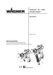
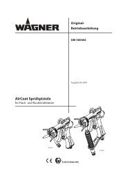
Translation of the originalOperating manual<strong>GM</strong> <strong>3000AC</strong>Edition 05/2007AirCoat spray gunwith flat or round jet nozzlesII 2G X (Atex 95)
EDITION 05/2007OPERATING MANUALPART NO. DOC364831<strong>GM</strong> <strong>3000AC</strong>Contents1 ABOUT THESE INSTRUCTIONS 51.1 Languages 51.2 Warnings, notes and symbols in these instructions 52 GENERAL SAFETY INSTRUCTIONS 62.1 Safety instructions for the operator 62.1.1 Electrical equipment 62.1.2 Personnel qualifications 62.1.3 A safe work environment 62.2 Safety instructions for staff 62.2.1 Safe handling of <strong>WAGNER</strong> spray units 72.2.2 Earth the unit 72.2.3 Material hoses 72.2.4 Cleaning 82.2.5 Handling hazardous liquids, varnishes and paints 82.2.6 Touching hot surfaces 82.3 Correct use 82.4 Use in an explosion hazard area 92.4.1 Correct use 92.4.2 Explosion protection identification 92.4.3 Max. surface temperature 92.4.4 Safety instructions 92.5 German regualtions and guidelines 103 PRODUCT LIABILITY AND WARRANTY 113.1 Important notes on product liability 113.2 Warranty 113.3 CE-conformity 124 DESCRIPTION 134.1 Area of application, using in accordance with the instructions 134.1.1 Processable materials 134.2 Scope of supply 134.2.1 HV-variants 134.2.2 LV-variants 144.2.3 Hot spraying HV-variants 144.2.4 LV-variants 160 bar; 16 MPa; 2320 psi 144.2.5 Standard equipment 154.3 Data 154.3.1 Materials of paint wetted parts 154.3 Technical Data 164.4 Functional description 174.4.1 Design of spraygun 174.4.2 Operation of the spraygun 174.5 Jet process 184.5.1 Aircoat flat jet process 184.5.2 Aircoat round jet process 195 PREPARATION BEFORE STARTING WORK 205.1 Set up and connect 203
EDITION 05/2007OPERATING MANUALPART NO. DOC364831<strong>GM</strong> <strong>3000AC</strong>Contents5.1.1 Typical aircoat installation 205.1.2 Ventilation of the spray booth 215.1.3 Air supply 215.1.4 Fluid (paint) hoses 215.1.5 Earthing 225.2 Preparation of paints 225.2.1 Viscosity conversion table 235.3 Start-up 245.3.1 General rules for making adjustments to the spray gun 245.3.2 Preparation 255.4 Working 265.4.1 Start-up aircoat spraying 265.4.2 Adjusting the spray pattern 265.4.3 Changing aircoat nozzle 275.4.4 Cleaning aircoat nozzles 285.4.5 Unblocking clogged nozzle 286 MAINTENANCE 296.1 Finishing work and cleaning 306.2 Changing or cleaning filter 316.3 Changing material hose 326.4 Replacing parts of the valve stem 336.4.1 Dismantling 336.4.2 Replacing seals in the valve tappet 346.4.3 Reassembling 346.5 Replacing nozzle seal 356.6 Replacing seal (distributor) 366.7 Changing or cleaning edge filter (optional) 377 TROUBLE SHOOTING AND SOLUTIONS 388 REPAIR WORK 398.1 Filter housing connection 398.2 pivot joint paint 428.3 Pivot joint paint LW 449 ACCESSORIES 469.1 AirCoat nozzles ACF3000 469.2 Air caps 489.3 Aircoat-nozzle round ACR3000 489.3.1 Nozzle inserts RXX 499.3.2 Nozzle screw joint assy. 499.4 filters for spray gun 499.5 Swivel for guns without filters 509.6 Hoses 519.7 Miscellaneous 5110 SPARE PARTS 5210.1 How to order spare parts? 5210.2 Spare parts list <strong>GM</strong> <strong>3000AC</strong> with filter 5310.3 Spare parts list <strong>GM</strong> <strong>3000AC</strong> without filter 5610.4 Spare parts list <strong>GM</strong> <strong>3000AC</strong>-H without filter 594
EDITION 05/2007OPERATING MANUALPART NO. DOC364831<strong>GM</strong> <strong>3000AC</strong>1 ABOUT THESE INSTRUCTIONS 1.1 LANGUAGESThis operating manual is available in the following languages:Language: Part No. Language: Part No.German364830 English364831French364832 Dutch364833Italian364834 Spanish364835Danish364836 Swedish364837Portuguese 364838 Polish3648391.2 WARNINGS, NOTES AND SYMBOLS IN THESE INSTRUCTIONSWarning instructions in this manual point out particular dangers to users and equipmentand state measures for avoiding the hazard. These warning instructions fall into the followingcategories:Danger - imminent danger. Non-observance will resultin death, serious injury and serious material damage. Warning - possible danger. Non-observance can resultin death, serious injury and serious material damage. Caution - a possibly hazardous situation. Non-observancecan result in minor injury. Caution - a possibly hazardous situation. Non-observancecan cause material damage. Note - provide information on particular characteristics and how to proceed.5
EDITION 05/2007OPERATING MANUALPART NO. DOC364831<strong>GM</strong> <strong>3000AC</strong>2 GENERAL SAFETY INSTRUCTIONS2.1 SAFETY INSTRUCTIONS FOR THE OPERATOR 2.1.1 ELECTRICAL EQUIPMENT 2.1.2 PERSONNEL QUALIFICATIONS 2.1.3 A SAFE WORK ENVIRONMENT 2.2 SAFETY INSTRUCTIONS FOR STAFF 6
EDITION 05/2007OPERATING MANUALPART NO. DOC364831<strong>GM</strong> <strong>3000AC</strong>2.2.1 SAFE HANDLING OF <strong>WAGNER</strong> SPRAY UNITSThe spray jet is under pressure and can cause dangerous injuries.Avoid injection of paint or cleaning agents: Never point the spray gun at people. Never reach into the spray jet. Before all work on the unit, in the event of work interruptions and functionalfaults:– Switch off the energy/compressed air supply.– Secure the spray gun against actuation.– Relieve the pressure from the spray gun and unit.– By functional faults: Identify and correct the problem, proceed as described inchap. „Trouble shooting“.In the event of skin injuries caused by paint or cleaning agents: Note down the paint or cleaning agent that you have been using. Consult a doctor immediately.Avoid danger of injury through recoil forces: Ensure that you have a firm footing when operating the spray gun. Only hold the spray gun briefly in any one position.2.2.2 EARTH THE UNIT 2.2.3 MATERIAL HOSES 7
EDITION 05/2007OPERATING MANUALPART NO. DOC364831<strong>GM</strong> <strong>3000AC</strong>2.2.4 CLEANING 2.2.5 HANDLING HAZARDOUS LIQUIDS, VARNISHES AND PAINTS 2.2.6 TOUCHING HOT SURFACES 2.3 CORRECT USE 8
EDITION 05/2007OPERATING MANUALPART NO. DOC364831<strong>GM</strong> <strong>3000AC</strong>2.4 USE IN AN EXPLOSION HAZARD AREA2.4.1 CORRECT USE 2.4.2 EXPLOSION PROTECTION IDENTIFICATION 2.4.3 MAX. SURFACE TEMPERATURE 2.4.4 SAFETY INSTRUCTIONS 9
EDITION 05/2007OPERATING MANUALPART NO. DOC364831<strong>GM</strong> <strong>3000AC</strong>2.5 GERMAN REGUALTIONS AND GUIDELINESa) BGV D15 Working with liquid ejection devicesb) BGV D25 Using coating materialsc) CHV 9 Regulations on flammable liquidsd) BGR 104 Explosion protection rulese) BGR 132 Avoiding ignition risksf ) BGR 180 Setting up for cleaning with solvents for cleaning workpieces withsolventsg) ZH 1/406 Guidelines for liquid ejection devicesh) BGI 740 Painting rooms and equipmentNote: All titles can be ordered from Heymanns Publishing House in Cologne or downloadfrom Internet10
EDITION 05/2007OPERATING MANUALPART NO. DOC364831<strong>GM</strong> <strong>3000AC</strong>3 PRODUCT LIABILITY AND WARRANTY3.1 IMPORTANT NOTES ON PRODUCT LIABILITY 3.2 WARRANTY 11
EDITION 05/2007OPERATING MANUALPART NO. DOC364831<strong>GM</strong> <strong>3000AC</strong>3.3 CE-CONFORMITYHerewith we declare that the supplied version of0364001 Spray gun <strong>GM</strong> <strong>3000AC</strong> Filter M16x1.5 HV0364002 Spray gun <strong>GM</strong> <strong>3000AC</strong> Filter NPS1/4“ HV0364003 Spray gun <strong>GM</strong> <strong>3000AC</strong> M16x1.5 HV0364004 Spray gun <strong>GM</strong> <strong>3000AC</strong> NPS1/4“ HV0364005 Spray gun <strong>GM</strong> <strong>3000AC</strong> Filter M16x1.5 LV0364006 Spray gun <strong>GM</strong> <strong>3000AC</strong> Filter NPS1/4“ LV0364007 Spray gun <strong>GM</strong> <strong>3000AC</strong> M16x1.5 LV0364008 Spray gun <strong>GM</strong> <strong>3000AC</strong> NPS1/4“ LV0364016 Spray gun <strong>GM</strong> <strong>3000AC</strong> 160 bar Filter NPS1/4“ LV0364018 Spray gun <strong>GM</strong> <strong>3000AC</strong> 160 bar NPS1/4“ LV0364020 Spray gun <strong>GM</strong> <strong>3000AC</strong>-H M16x1.5 HVComplies with the following provisons apllying to it:98/37/EG94/9/EGApplied standards, in particular:EN 292-1 EN 1127-1EN 292-2 EN 1953EN 563 EN 3746EN 1050 EN 13463-1Applied national technical standards and specifications, in particular:see chapter. 2.5CE Certificate of ConformityThe certificate is enclosed with this product.The certificate of conformity can be reorderedfrom your <strong>WAGNER</strong> representative, quoting the product and serial number.Part number:<strong>GM</strong> <strong>3000AC</strong>0364900_a12
EDITION 05/2007OPERATING MANUALPART NO. DOC364831<strong>GM</strong> <strong>3000AC</strong>4 DESCRIPTION4.1 AREA OF APPLICATION, USING IN ACCORDANCE WITH THE INSTRUCTIONSThe gun is suitable for atomising liquid materials, particularly coating materials, using theAirCoat process.4.1.1 PROCESSABLE MATERIALSTop-coat paints, primer paints, corrosion protection solvents, textured paints, lyes, stainingsolvents, clear paints, parting solvents, etc. on a solvent or water basis.SIHI_0019_GBHot coating substances!BurnsWARNING Wear antistatic protective gloves. When operating the unit with a coating material with a temperaturegreater than 43°C; 109.4°F: Identify the unit with a warningsticker "Warning - hot surface".Note:In the event of application problems, contact your <strong>WAGNER</strong> branch and the paint manufacturer.4.2 SCOPE OF SUPPLYThe AirCoat gun is available in different variants as shown below. In accessories differentflat nozzles and round jet nozzles are available. The nozzle size depends on the paint andon the application. Therefore the nozzle is not included in the scope of supply. For a nozzlelist and other accessories look in chapter 9.4.2.1 HV-VARIANTSThese guns have a blue air cap. This air cap is specially designed for high viscosity (HV)material.Qty Part-No. AirCoat gun1 0364001 <strong>GM</strong> <strong>3000AC</strong> with filter + M16x1.5“ material connector HV1 0364002 <strong>GM</strong> <strong>3000AC</strong> with filter + NPSM1/4“ material connectors HV1 0364030 <strong>GM</strong> <strong>3000AC</strong> with filter + NPSM1/4“ material connector HV USA1 0364003 <strong>GM</strong> <strong>3000AC</strong> without filter + M16x1.5“ material connector HV1 0364004 <strong>GM</strong> <strong>3000AC</strong> without filter + NPSM1/4“ material connector HV1 0364031 <strong>GM</strong> <strong>3000AC</strong> with filter + NPSM1/4“ material connector HV USA13
EDITION 05/2007OPERATING MANUALPART NO. DOC364831<strong>GM</strong> <strong>3000AC</strong>4.2.2 LV-VARIANTSThese guns have a red air cap. This air cap is specially designed for low viscosity (LV) material.Qty Part-No. AirCoat gun1 0364005 <strong>GM</strong> <strong>3000AC</strong> with filter + M16x1.5“ material connector LV1 0364006 <strong>GM</strong> <strong>3000AC</strong> with filter + NPSM1/4“ material connector LV1 0364032 <strong>GM</strong> <strong>3000AC</strong> with filter + NPSM1/4“ material connector LV USA1 0364007 <strong>GM</strong> <strong>3000AC</strong> without filter + M16x1.5“ material connector LV1 0364008 <strong>GM</strong> <strong>3000AC</strong> without filter + NPSM1/4“ material connector LV1 0364033 <strong>GM</strong> <strong>3000AC</strong> with filter + NPSM1/4“ material connector LV USA4.2.3 HOT SPRAYING HV-VARIANTSThese guns have a blue air cap. This air cap is specially designed for high viscosity (HV)material and for hot spraying.Qty Part-No. AirCoat gun1 0364020 <strong>GM</strong> <strong>3000AC</strong>-H without filter + M16x1.5 material connector HV4.2.4 LV-VARIANTS 160 BAR; 16 MPA; 2320 PSIThese guns have a red air cap. This air cap is specially designed for low viscosity (LV) material.Qty Part-No. AirCoat gun1 0364016 <strong>GM</strong> <strong>3000AC</strong> 16 MPa; 160 bar; 2320 psi with filter + NPSM1/4“material connector LV1 0364034 <strong>GM</strong> <strong>3000AC</strong> 16 MPa; 160 bar; 2320 psi with filter + NPSM1/4“material connector LV USA1 0364018 <strong>GM</strong> <strong>3000AC</strong> 16 MPa; 160 bar; 2320 psi without filter + NPSM1/4“material connector LV1 0364035 <strong>GM</strong> <strong>3000AC</strong> 16 MPa; 160 bar; 2320 psi without filter + NPSM1/4“material connector LV USA14
EDITION 05/2007OPERATING MANUALPART NO. DOC364831<strong>GM</strong> <strong>3000AC</strong>4.2.5 STANDARD EQUIPMENTThe standard equipment includes:QuantityDescription03640010364002036400303640040364005036400603640070364008036402003640160364018Part No.AirCoat manual gun <strong>GM</strong> <strong>3000AC</strong>1 1 1 1 1 1 1 1 1 1 1 8780111 Double-ended open-jaw spanner 13x171 1 1 1 1 1 1 1 1 1 1 9991401 Double-ended open-jaw spanner 17x19- - - - 1 1 - - - 1 - 0043235 Push-in filtre yellow (installed: push-in filtre red)1 1 - - - - - - - - - 0034383 Push-in filtre red (installed: push-in filtre yellow)1 1 1 1 - - - - 1 - - 0364911 Air cap HV (blue)- - - - 1 1 1 1 - 1 1 0364910 Air cap HV (red)1 1 1 1 1 1 1 1 1 1 1 0364900 CE-Declaration of Conformity1 1 1 1 1 1 1 1 1 1 1 364830 Operating manual German1 1 1 1 1 1 1 1 1 1 1 see 1.0 An operating manual in the local languageThe standard equipment includes:QuantityDescription036403003640310364032036403303640340364035Part No.AirCoat manual gun <strong>GM</strong> <strong>3000AC</strong> USA1 1 1 1 1 1 8780111 Double-ended open-jaw spanner 13x171 1 1 1 1 1 9991401 Double-ended open-jaw spanner 17x19- - 1 - - - 0043235 Push-in filtre yellow (installed: push-in filtre red)1 - - - 1 - 0034383 Push-in filtre red (installed: push-in filtre yellow)1 1 - - - - 0364911 Air cap HV (blue)- - 1 1 1 1 0364910 Air cap HV (red)1 1 1 1 1 1 0364900 CE-Declaration of Conformity1 1 1 1 1 1 364831 Operating manual English1 1 1 1 1 1 see 1.0 An operating manual in the local languageFor special versions the delivery note applies.4.3 DATA4.3.1 MATERIALS OF PAINT WETTED PARTSSteelPlasticsTungsten carbide Stainl. steel 1.4305 UHMW-PE FPM PA 6.6Stainl. steel 1.4310 Stainl. steel 1.4104 PTFE POM15
EDITION 05/2007OPERATING MANUALPART NO. DOC364831<strong>GM</strong> <strong>3000AC</strong>4.3 TECHNICAL DATADescriptionUnits03640010364002Max. air pressure MPa 0.8psi 120bar 8Max. materialpressure03640030364004036403003640310364005MPa 25 16psi 3625 2320bar 250 160Mat. flow volume l/min*cc/min.Materia connector mm x - x - - - x - x - - - x - - - -M16x1.5Material connector Inches - x - x - x - x - xNPS 1/4“Air connection Inches G1/4“Filter (accessory) Meshes ** ** - - ** - ** ** - - ** - - ** - ** -Weightg 723 723 520 520 723 520 723 723 520 520 723 520 520 723 520 723 520oz 25.5 25.5 18.3 18.3 25.5 18.3 25.5 25.5 18.3 18.3 25.5 18.3 18.3 25.5 18.3 25.5 18.3Max. temperaturematerial°C°F551318017655131Max. temperatureair°C°F43109dB(A) 76.0 76.5 76.0 76.5Sound level at 0.3MPa; 3 bar; 43.5 psiair pressure and11 MPa; 110 bar;1549 psi materialpressure**** According to nozzle, see chapter 9.1.** Filter types see paragr. 9.6*** A rated sound pressure level meassured in 0.5m distance according to DIN EN ISO 3746-19950364006036400703640080364032036403303640200364016036401803640340364035Dimensions<strong>GM</strong> <strong>3000AC</strong> with filter <strong>GM</strong> <strong>3000AC</strong> without filter 16
EDITION 05/2007PART NO. DOC364831<strong>GM</strong> <strong>3000AC</strong>OPERATING MANUAL4.4 FUNCTIONAL DESCRIPTION4.4.1 DESIGN OF SPRAYGUN<strong>GM</strong> <strong>3000AC</strong> with filter<strong>GM</strong> <strong>3000AC</strong> without filterDescriptionDescriptionA Suspension hook H Aircap nut and nozzle guardB Shaping air control knob I Nozzle / air capC Tension cap J Spraygun bodyD Trigger K Filter housingE Safety catch L Tube handleF Air connector M Pivot joint, materialG Material connector N Pivot joint, air4.4.2 OPERATION OF THE SPRAYGUNPulling the trigger (D) approximately 1/2 way opens the air valve allowing atomising andshaping-air to flow through the aircap. When the trigger is pulled further, more resistanceis felt and the material valve is opened. The atomising air control adjusts the total quantityof air flowing trough the spray gun.The spray gun is rendered safe with the trigger safety catch (E). (Turn the trigger safetycatch in the spraying direction and fasten in the groove)17
EDITION 05/2007OPERATING MANUALPART NO. DOC364831<strong>GM</strong> <strong>3000AC</strong>4.5 JET PROCESS4.5.1 AIRCOAT FLAT JET PROCESSWith the AirCoat process the spray material is atomized at a pressure of 3-12 MPa; 30-120bar; 435-1740 psi. A soft, flat spray is achieved with help of the AirCoat air, which has a pressureof 0.05-0.25 MPa; 0.5-2.5 bar; 7.2-36 psi. The shaping air (C) provides the potential tomake the width of the spray jet larger and smaller.Air capShaping airAtomizing airSpray jet width adjustableB_00001AdvantagesHigh painting capacityLow mist formationGood finishHigh-solids paints can easily be applied• Adjustable spray fan.18
EDITION 05/2007OPERATING MANUALPART NO. DOC364831<strong>GM</strong> <strong>3000AC</strong>4.5.2 AIRCOAT ROUND JET PROCESSIn the AirCoat process, high pressure of 3-12 MPa; 30-120 bar; 435-1740 psi is used to atomizethe material.The AirCoat air at 0.05-0.25 MPa; 0.5-2.5 bar; 7.2-36 psi produces a soft jet, which largelyeliminates the problem of overlapping boundaries.The spray jet can be adjusted by turning the nozzle nut. The multi-channel swirl nozzleproduces fine paint particles, while at the same time reducing their forwards speed andswirling them to produce a rotating motion. The result is a soft, extremely well atomizedspraying cloud.AirCoat-airMaterialAirCoat-airNozzle nutMulti-channel swirl nozzleSpray jetAdvantagesHigh painting capacityLow fogging tendencyGood finish• High- viscosity paints can easily be applied19
EDITION 05/2007OPERATING MANUALPART NO. DOC364831<strong>GM</strong> <strong>3000AC</strong>5 PREPARATION BEFORE STARTING WORK5.1 SET UP AND CONNECT5.1.1 TYPICAL AIRCOAT INSTALLATIONSIHI_0050_GBWARNINGIncorrect installation/operation!Risk of injury and damage to equipment When putting into operation and for all work, read and followthe operating instructions and safety regulations for the additionallyrequired system components. ABCDEFGHIJKLMPaint-pumpAir shut-off valveAir regulatorAir regulator with filterEarthing cableAir hose (electrically conductive)AirCoat spray gunHP-fluid hoseHP-filter/ relief valveRelief tubeStand TrolleySuction systemMains air inletThe spray gun <strong>GM</strong> <strong>3000AC</strong> must be used apart of an AirCoat spraying system. The Air-Coat system shown in the figure is only oneexample of an AirCoat spraying system. Contactyour <strong>WAGNER</strong> distributor for assistancein designing a system to meet your needs.The operating instructions and the safety regulations for the additional system componentsused must be read before starting-up20
EDITION 05/2007OPERATING MANUALPART NO. DOC364831<strong>GM</strong> <strong>3000AC</strong>5.1.2 VENTILATION OF THE SPRAY BOOTHSIHI_0028_GBWARNINGToxic and/or flammable vapor mixtures!Risk of poisoning and burns Operate the unit in a spraying booth approved for the workingmaterials.-or- Operate the unit on an appropriate spraying wall with the ventilation(extraction) switched on. Observe national and local regulations for the outgoing airspeed.5.1.3 AIR SUPPLYThe use of an air filter with the air regulator (D) ensures that only dry, clean atomising airgets into the spray gun. Dirt and moisture in the atomising air reduce the spraying qualityand the appearance of the finished piece.5.1.4 FLUID (PAINT) HOSES SIHI_0029_GBDANGERBursting hose, bursting threaded joints!Danger to life from injection of material Ensure that the hose material is chemically resistant. Ensure that the spray gun, threaded joints and material hosebetween the unit and the spray gun is suitable for the pressuregenerated in the unit. Ensure that the following information can be seen on the highpressurehose:- Manufacturer- Permissible operating pressure- Date of manufacture.21
EDITION 05/2007OPERATING MANUALPART NO. DOC364831<strong>GM</strong> <strong>3000AC</strong>5.1.5 EARTHING WARNINGHeavy paint mist if earthing is insufficient!Risk of poisoningInsufficient paint application quality Earth all unit components. Earth the workpieces being painted.SIHI_0003_GBAny material containers and the unit must be connected by a potential equalisation (earth)cable.5.2 PREPARATION OF PAINTSThe viscosity of the paint is of great importance. The best results are obtained for paints of80 and 150 milli Pascal x Sec (mPas).In most cases, the application of paints of up to 260 mPas for high film-thicknesses doesnot cause any problems.22
EDITION 05/2007OPERATING MANUALPART NO. DOC364831<strong>GM</strong> <strong>3000AC</strong>5.2.1 VISCOSITY CONVERSION TABLE 23
EDITION 05/2007OPERATING MANUALPART NO. DOC364831<strong>GM</strong> <strong>3000AC</strong>5.3 START-UP5.3.1 GENERAL RULES FOR MAKING ADJUSTMENTS TO THE SPRAY GUN➞ See safety regulations in chapter 2.SIHI_0065_GBWARNINGUnintentional putting into operation!Risk of injuryBefore all work on the unit, in the event of work interruptions andfunctional faults: Switch off the energy/compressed air supply. Relieve the pressure from the spray gun and unit. Secure the spray gun against actuation. By functional faults: Identify and correct the problem, proceedas described in chap„Trouble shooting“.Cleaning agent in the air duct!Functional faults caused by swollen sealsCAUTION Always point the spray gun down when cleaning. Ensure that neither paint nor cleaning agent enters the air duct.SIHI_0005_GBTrigger safety catch in on(safe) positionAirAirB 00036MaterialMaterial24
EDITION 05/2007OPERATING MANUALPART NO. DOC364831<strong>GM</strong> <strong>3000AC</strong>5.3.2 PREPARATION1. Secure the spraygun.2. Connect material hose to spray gun and to pump.3. Connect air hose to spray gun and to oil-free, dry air supply with regulator.4. Insert suitable gun filter.5. Tighten the complete gun handle/ swivel assembly.6. Place the nozzle into the nozzle seal. Fit the aircap over the nozzle, ensuring that thelocation flats (X) are in line. Fit the aircap nut with nozzle guard and tighten by hand.XNote:The pin in the housing is to adjust the spray jet in the horizontal or vertical position.7. Visually check the permissible pressures for all the system components.8. Make sure that the spraying unit and all other conductive parts within the work areaare earthed9. Set material pressure approx. 100 bar; 10 MPa; 1450 psi and use a suitable medium(solvent or water) to check that connections do not leak.Note:Pull the trigger and then release, checking that the gun closes cleany.10. Relieve spray gun and unit pressure and secure the spraygun.25
EDITION 05/2007OPERATING MANUALPART NO. DOC364831<strong>GM</strong> <strong>3000AC</strong>5.4 WORKING5.4.1 START-UP AIRCOAT SPRAYING1. Set material pressure to approx. 8MPa; 80 bar; 1160 psi at material pump.2. Spray (release trigger safety catch and pull trigger) and check the atomisation.3. Set the fluid pressure to the point where a further increase in fluid pressure wouldsignificantly improve fluid atomization.4. Now open AirCoat-air on the atomizing air regulator and set.5. Adjust the pressure to get the optimum spraying finish. Relation between spray patternand atomizing air see illustration. Set the minimum air pressure necessary to achievethe best possible spray pattern.Note:Repeat point 4 and 5 until the optimum spray pattern is reachedSpray patternsB_00071no atomizing air too little atomizing air correct amount of atomizing air5.4.2 ADJUSTING THE SPRAY PATTERNThe spray pattern can be adjusted to suit the object Being sprayed using the shaping airregulator. The illustration below shows the influence of the shaping air regulator on thespraying pattern.Other tip sizes can be used to obtain larger or smaller spraying patterns.Shaping air fullyclosedShaping air fullyopenNoteThe paint output volume can be changed by:Changing the material pressure.• Fitting another flat jet nozzle. See accessories.Viewed from rear of spraygun26
EDITION 05/2007OPERATING MANUALPART NO. DOC364831<strong>GM</strong> <strong>3000AC</strong>5.4.3 CHANGING AIRCOAT NOZZLEDefective AirCoat nozzle!Insufficient paint application qualityCAUTION Do not use sharp-edged objects to treat hard metal on the AirCoat nozzle.SIHI_0020_GBCAUTIONDefective nozzle seal!Material sprays into the air cap next to the nozzleRisk of contamination Do not clean the nozzle seal with sharp-edged objects. Replace the nozzle seal if the sealing surface is damaged.SIHI_0021_GB1. Relieve the pressure from the gun and unit.2. Secure gun with trigger safety catch.3. Unscrew aircap nut (A)4. Remove air cap (B) and nozzle (C).5. Press AirCoat nozzle (C) out of the air cap by hand and brush with cleaning solventuntil all remaining paint has been dissolved.6. Assembly:Place AirCoat nozzle (C) in nozzle seal (D).7. Place air cap (B) on the nozzle (C). Take care that the nozzle fitted is correctly (see flatsX)8. Fit the aircap nut with nozzle guard (A) over the air cap (B) onto the spray gun andtighten by hand.XABCDB_0004227
EDITION 05/2007OPERATING MANUALPART NO. DOC364831<strong>GM</strong> <strong>3000AC</strong>5.4.4 CLEANING AIRCOAT NOZZLESFor disassembly and assembly see AirCoat nozzles section 5.4.3.The AirCoat nozzle (C) can be placed into a cleaning solvent which has been recommendedby the paint manufacturer.5.4.5 UNBLOCKING CLOGGED NOZZLE1. Relieve the pressure from the gun and unit.2. Secure gun with trigger safety catch.3. Unscrew aircap nut with nozzle guard (A).4. Remove aircap (B).5. Pull out the clogged nozzle (C) from the air cap (B), reverse it and replace it into nozzle seal(D).6. Place air cap (B) on the nozzle (C). Take care that the nozzle fitted is correctly(see flats X)7. Fit the aircap nut with nozzle guard (A) over the air cap (B) onto the spray gun andtighten by hand.8. Switch the material pressure back on.9. Turn the safety catch to the spraying position and briefly pull trigger.10. When the blockage has been flushed out secure the gun with safety catch.11. Relieve the pressure from the gun and unit.12. Unscrew aircap nut with nozzle guard (A).13. Remove air cap (B) and reverse nozzle (C) again.14. Refit air cap (B) on the nozzle (C). Take care that the nozzle fitted is correctly (see flatside X)15. Fit the aircap nut with nozzle guard (A) over the air cap (B) onto the spray gun andtighten by hand.16. Switch the material pressure and the air pressure back on.XNozzle in „spray“ positionDABCB_00039Nozzle in „cleaning“ position28
EDITION 05/2007OPERATING MANUALPART NO. DOC364831<strong>GM</strong> <strong>3000AC</strong>6 MAINTENANCE➞ See safety regulations in chapter 2.The spray gun and the unit must be cleaned every day. Use only the cleaning solvent recommendedby the material manufacture.Cleaning agent in the air duct!Functional faults caused by swollen sealsCAUTION Never immerse the spray gun in cleaning agent.SIHI_0066_GBWARNINGIncorrect maintenance/repair!Risk of injury and damage to the equipment Repairs and part replacement may only be carried out by speciallytrained staff or a <strong>WAGNER</strong> service center. Before all work on the unit and in the event of work interruptions:- Switch off the energy/compressed air supply.- Relieve the pressure from the spray gun and unit.- Secure the spray gun against actuation. Observe the operating and service instructions when carryingout all work.SIHI_0004_GB29
EDITION 05/2007OPERATING MANUALPART NO. DOC364831<strong>GM</strong> <strong>3000AC</strong>6.1 FINISHING WORK AND CLEANINGDANGERExploding gas/ air mixture!Danger to life from flying parts and burns Never spray into a closed container. Earth the container.SIHI_0008_GBCleaning agent in the air duct!Functional faults caused by swollen sealsCAUTION Always point the spray gun down when cleaning. Ensure that neither paint nor cleaning agent enters the air duct.SIHI_0005_GB Note:Methylene chloride is not recommended as a flushing or cleaning solvent with this gun orany system components.1. Relieve the pressure from the gun and unit.2. Secure gun with trigger safety catch.3. Replace material with cleaning agent.4. Remove and clean the AirCoat nozzle. (see section 5.4.3)5. Pressurize the cleaning supply to approx. 4 MPa; 40 bar; 580 psi max. and thoroughlyflush the spray gun.6. Relieve spray gun and unit pressure!7. Secure gun with trigger safety catch.8. Clean gun body with a cleaning agent recommended by the manufacturer, and drywith a cloth.30
EDITION 05/2007OPERATING MANUALPART NO. DOC364831<strong>GM</strong> <strong>3000AC</strong>6.2 CHANGING OR CLEANING FILTER1. Take spraygun out of operation and clean.2. Relieve the pressure from the gun and unit.3. Secure gun with trigger safety catch.4. Unscrew the complete swivel assembly with the filter housing, and remove downwardswith the hose.5. Remove the filter insert (A) from the filter housing (B).6. Clean the swivel, filter housing and filter (A) with cleaning agent.7. Fit the cleaned or new filter insert (A) into the filter housing with the conical end (X)pointing upwards.8. Push the filter housing over the swivel hexagon, then slide the whole assembly overthe gun filter and tighten by hand.XUnscrewTighten CounterNote:In case of difficulty unsrewing the filterhousing use 2 open-ended wrenches(13 mm; 0.512 inch / 17 mm; 0.70 inch)Unscrew Note:Do not unscrew the paint connection. The nut must only be unscrewed by<strong>WAGNER</strong>- Service-Agency.31
EDITION 05/2007PART NO. DOC364831<strong>GM</strong> <strong>3000AC</strong>OPERATING MANUAL6.3 CHANGING MATERIAL HOSE1. Put out of operation and clean.2. Relieve the pressure from the gun and unit.3. Secure gun with trigger safety catch.4. Place open-ended wrench 13 mm; 0.51 inch respectively 17 mm; 0.70 inch on flats of paintconnection respectively swivel and counterhold.5. Turn nut to the right with open-ended wrench 19 mm; 0.75 inch and unscrew material hose.6. Assembly:Fit the material hose by hand and tighten with 2 open-ended wrenches13 mm; 0.51 inch; 19 mm; 0.75 inch respectively 17 mm; 0.70 inch; 19 mm; 0.75 inchSW 19 mm; 0.75 inchSW 13 mm; 0.51 inchSW 19 mm; 0.75 inchCounterpressureB_00059SW 17 mm; 0.70 incCounterpressureNote:Do not unscrew the paint connection. The nut must only be unscrewed by <strong>WAGNER</strong>- Service-Agency.B_0003632
EDITION 05/2007OPERATING MANUALPART NO. DOC364831<strong>GM</strong> <strong>3000AC</strong>6.4 REPLACING PARTS OF THE VALVE STEM6.4.1 DISMANTLING1. Take spraygun out of operation and clean.2. Relieve the pressure from the gun and unit.3. Secure gun with trigger safety catch.4. Unscrew the tension cap (A) remove the springs (B) and (C).5. Remove trigger pin (H) and screw (J).6. Remove the trigger (I).7. Loosen packing screw (G) with open-ended wrench 7 mm; 0.275 inch .8. Push the valve tappet (E) together with the valve rod (D) backwards by hand.9. Using pliers pull out parts (E) and (D).Unsuitable tool!Damage to seals and sealing surfacesCAUTION Do not hold the valve rod with pliers or a similar tool.SIHI_0006_GB10. Remove packing screw (G) with open-ended wrench 7 mm; 0.275 inch.11. Remove sealing package (F).Note:If parts remain stuck in the hole then remove the air cap (M) with the nozzle (L), thenthe valve seat holder (K) using a 12 mm; 0.472 inch wrench and remove. The stuckcomponents can then be pushed out with a drift max. ø 4.5 mm; 0.177 inch.12. Exchange any worn parts.Sealing surfaceTightening torque 10 Nm; 7.4 lbftREDNMLKGCBAHJFTightening torque 8 Nm; 5.9 lbftIB_0006433
EDITION 05/2007OPERATING MANUALPART NO. DOC364831<strong>GM</strong> <strong>3000AC</strong>6.4.2 REPLACING SEALS IN THE VALVE TAPPET1. Heat valve tappet assy. to about 150°C; 302°F.2. Place a 7 mm; o.28 inch wrench on the valve tappet (E) and hold. Unscrewthe tappet cap (Q) with an 8 mm; 0.31 inch wrench.3. Remove and replace tappet seal (O) and seal (P).Note:The seal (O) can be unscrewed from the valve tappet (E) using a small screwdriverpushed into it When the air-valve leaks:4. Remove the air-valve seal (R) fromthe gun-housing and replace. Cleansealing surfaces in the gun housing.When the slide cap (S) is damaged:5. Cut the slide cap (S) with a shrap knifeand press a new one onto the tappetcap.RDisassembly tool for airvalveseal (R)Part-No. 036 943Assembly tool for airvalveseal (R)Part-No. 03649426.4.3 REASSEMBLING1. Screw in the valve seat (K) and tighten using a 12 mm; 0.472 inch torque wrench to atorque of 10 Nm; 7.4 lbft.2 See section 5.4.3 for reassembly of air-cap.3. Lightly grease the tappet seal (O) and the seal (P) and assemble on valve tappet (E).4. Push in valve stem (D).Note:Only silicon-free or resin-free grease is permitted to be used.5. Screw the air valve tappet (E) and tappet cap (Q) together using loctite 243 by hand.Carefully tighten using 7 mm; 0.275 inch / 8 mm; 0.314 inch wrenches until slightresistance is felt when sliding the valve stem in and out.6. Place the seal package (F) on the valve rod (D) and insert into the hole in the housingfrom the rear.34
EDITION 05/2007OPERATING MANUALPART NO. DOC364831<strong>GM</strong> <strong>3000AC</strong>7. Pull the valve rod (D) out again.8. Screw in the packing screw (G) and do not tighten fully.9. Put trigger (I) in position, and insert trigger pin (H) and screw ( J).10. Place the valve tappet (E) over the valve rod (D). Push both parts from behind into thehousing.11. Place the springs (C) and (B) in place and tighten tension cap (A).to a torque of 8 Nm;5.9 lbft.12. Tighten seal package (F) with packing screw (G) carefully. Take care of a smoothmovement of trigger.13. Start-up see chapter 5.3.Note:Ensure that the springs plates in the sealing package (F)are in the correct position.6.5 REPLACING NOZZLE SEALCAUTIONForming air and atomizer air not separate !Poor spray patternSpray jet cannot be adjusted Treat the distributor seal (F) with care.SIHI_0030_GB1. Take out of operation and clean.2. Relieve the pressure from the gun and unit.3. Secure gun with trigger safety catch.4. Unscrew aircap nut with nozzle guard (A)5. Remove air cap (B) and nozzle (C).6. Prise the tip seal (D) out using a small screwdriver.7. Push the new nozzle seal into the valve seat holder (E).8. Re-assemble aircap in reverse orderAB C DEFB_0003335
EDITION 05/2007OPERATING MANUALPART NO. DOC364831<strong>GM</strong> <strong>3000AC</strong>6.6 REPLACING SEAL (DISTRIBUTOR)1. Take out of operation and clean.2. Relieve the pressure from the gun and unit.3. Secure gun with trigger safety catch.4. Unscrew aircap nut with nozzle guard (A)5. Remove air cap (B) and nozzle (C).6. Pull the damaged seal (F) out using a pliers7. Assembly: Put the new seal (F) on the air cap (B).8. Place the air cap and seal into gun housing.9. Set aircap nut (A) and screw in as far as the seal ring (F) in the groove catches. (snaphearable)10. Disassemble aircap nut and aircap an complete the spray gun. See chapter 5.4.3.1.ABC2.3.F4. 5.B_0006636
EDITION 05/2007OPERATING MANUALPART NO. DOC364831<strong>GM</strong> <strong>3000AC</strong>6.7 CHANGING OR CLEANING EDGE FILTER (OPTIONAL)1. Put out of operation and clean.2. Relieve the pressure from the gun and unit.3. Secure gun with trigger safety catch.4. Place open-ended wrench 19 mm; 0.75 inch respectively 17 mm; 0.70 inch on flats offilter housing (B) respectively swivel (C) and counterhold.5. Turn nut to the right with open-ended wrench 17 mm; 0.70 inch and unscrew pivotjoint (C) with material hose.6. Remove edge filter (A)7. Clean the filter housing (B) respectively swivel (C) and edge filter (A) with cleaningagent.8. Assembly:Fit the cleaned or new edge filter into the pivot joint (C).9. Fit pivot joint with the material hose by hand and tighten with 2 open-ended wrenches17 mm; 0.70 inch / 19 mm; 0.748 inch.BSW 19 mm; 0.75 inchCounterpressureACSW 17 mm;0.70 inchB_0006737
EDITION 05/2007OPERATING MANUALPART NO. DOC364831<strong>GM</strong> <strong>3000AC</strong>7 TROUBLE SHOOTING AND SOLUTIONSProblem Cause SolutionPaint output too low Nozzle too small Select larger nozzle (see para. 9.1)Poor quality spray patternLeaking valve stem seals(paint or air)Spaygun will not shut-offcorrectlyPaint pressure too low Adjust at pump as required.Gun filter blocked Clean/ replace filters (see para. 6.1)or HP filter at pumpcloggedNozzle blocked or Clean nozzle (see section 5.4.5)Trigger/ valve stem Replace valve stemdefectiveIncorrect atomizing air Re-adjust (see para. 5.4.1)pressureNozzle too large Select smaller nozzle (see para. 9.1)Paint pressure too low Increase pressure at pumpMaterial viscosity toohighThin material acc. to manufacturer‘sinstruction.Partial nozzle blokkage Clean nozzle (see para. 5.4.5)Incorrect fanairadjustment (fan towide or to narrow)Aircap faulty (blockedholes, damaged seal)Re-adjust fanair control on spraygun (seepara. 5.4.1)Clean or replace aircapWrong aircap type Replace as requiered (solvent /waterbased)Paint seal (packing)amaged or worn, valvestem damaged.Air valve sealsdamaged.Pretension to lowWorn valveseat / valveballPacking-screw tootight, or packing stuckwith dried paintAdjust or replace packing or replace valvestem cpl.Replace air valve seals (see para. 6.3)Tighten the sealing screwReplace as requiredRetension or replace packing38
EDITION 05/2007OPERATING MANUALPART NO. DOC364831<strong>GM</strong> <strong>3000AC</strong>8 REPAIR WORKSIHI_0004_GB➞ See safety regulations in chapter 2.WARNINGIncorrect maintenance/repair!Risk of injury and damage to the equipment Repairs and part replacement may only be carried out by speciallytrained staff or a <strong>WAGNER</strong> service center. Before all work on the unit and in the event of work interruptions:- Switch off the energy/compressed air supply.- Relieve the pressure from the spray gun and unit.- Secure the spray gun against actuation. Observe the operating and service instructions when carryingout all work.8.1 FILTER HOUSING CONNECTION1Heat up to approx. 150°C;302°F with a hot air fans.23SW 13 mm 415 Nm; 11.1 lbft657B_0003139
EDITION 05/2007OPERATING MANUALPART NO. DOC364831<strong>GM</strong> <strong>3000AC</strong>Disassembly1. Remove all moving parts of the spray-gun2. Heat up to approx. 150°C; 302°F the area of the banjo bolt (4).3. Unscrew banjo bolt (4) with open-end wrench (size 13 mm; 0.51 inch) and remove filterhousing (5) with seal material (7) or material outlet fitting (8).4. Clean all reusable parts using a suitable solvent.❋Heat up to approx. 150°C;302°F with a hot air fans.1❋234SW 13 mm15 Nm; 11.1 lbft68B_0003040
EDITION 05/2007OPERATING MANUALPART NO. DOC364831<strong>GM</strong> <strong>3000AC</strong>Repair spare partsItem K Qty Part-No. Description1 1 0364927 Gun housing pre-assembled filter1 1 0364928 Gun housing pre-assy. M16x1.51 1 0364929 Gun housing pre-assy. NPSM1/4“1 1 0364934 Gun housing AC-H M16x1.52 1 0364339 Seal material inlet3 1 9922720 Snap ring4 1 0364336 Banjo bolt5 1 0364343 Filter housing bended6 1 9992833 Loctite 638 green7 1 0364340 Seal filter8 1 0364353 Material outlet fitting M16x1.58 1 0364355 Material outlet fitting NPSM1/4“9 1 9992528 Loctite 270Assembly1. Push the new banjo bolt (4) onto filter housing (5) or onto material outlet nipple (8).2. Place the snap ring (3) in the groove of filter housing (5) and place the seal material (2)onto filter housing (5).3. Apply loctite 638 to the thread of the bajo bolt (4) and of the filter pipe (5).4. Push complete filter housing or material outlet fitting onto gun housing and ensurethat it is in the correct position. Tighten the banjo bolt (4) using a torque wrench to atorque of 15 Nm; 11 lbft.5. Put the cemented joint for 30 minutes at 40°C; 104°F in a oven.6. Assemble the spraygun and check the gun for leaks using solvent or spray oil and amax. pressure of 25 MPa; 250 bar; 3626 psi or 16 MPa; 160 bar; 2320 psi.7. Check the gun for leaks using solvent or spray oil and a max. pressure of 25 MPa; 250bar; 3626 psi or 16 MPa; 160 bar; 2320 psi41
EDITION 05/2007OPERATING MANUALPART NO. DOC364831<strong>GM</strong> <strong>3000AC</strong>8.2 PIVOT JOINT PAINT Disassembly1. Remove pressure spring (1) and unscrew adjuster screw (2).2. Remove o-ring (3) and gasket (4).Item K Qty Part-No. Description1 1 0043590 Pressure spring2 1 0364374 Adjuster screw3 1 9971147 O-ring4 1 0364375 Gasket5 1 0364923 Pivot joint paint M16x1,55 1 0364924 Pivot joint paint NPSM1/4“-186 1 9992528 Loctite 2707 1 9992695 Castor oilAssembly1. Lightly grease o-ring (3) using castor oil and push it ontogasket (4). Insert the gasket assy. into connection piece.NoteBy assembling do not damage gasket (4).2. Screw adjuster screw (2) into connection piece using Loctite270.NoteDo not thighten fully the adjuster screw.3. Tighten the adjuster screw (2) using a torque wrench to atorque of 1.5 Nm ± 0.5 Nm ; 1.84 lbft ± 0.37 lbft .4. Push the pressure spring (1) onto the adjuster screw (2).5. Put the assembled part for 30 minutes at 40°C; 104°F in a oven.NoteThe part must be placed in the oven on the connection piece.(Pressure spring downstairs)6. Check the pivot joint for leaks using solvent or spray oil and amax. pressure of 25 MPa; 250 bar; 3626 psi or 16 MPa; 160 bar;2320 psi.1.0 Nm ±0.5 Nm ;0.74 lbft ±0.36lbft671234B_0129342
EDITION 05/2007OPERATING MANUALPART NO. DOC364831<strong>GM</strong> <strong>3000AC</strong>Dimensional accuracy:If the distance „x“ between pinhead (1) and distance piece (2) is larger than 1.5 mm; 0.06inches, the pivot joint must be replaced.max. 1.5 mm0.06 inch max.2X1B_0129243
EDITION 05/2007OPERATING MANUALPART NO. DOC364831<strong>GM</strong> <strong>3000AC</strong>8.3 PIVOT JOINT PAINT LW Disassembly1. Unscrew the filter housing (1) from the connection piece and remove the edge filter(6) and nipple (5).2. Unscrew adjuster screw (2). Remove o-ring (3) and gasket (4).Item K Qty Part-No. Description1 1 0364379 Filter housing M16x1.5 LW1 1 0364380 Filter housing NPS1/4“-18 LW2 1 0364374 Adjuster screw3 1 9971147 O-ring4 1 0364375 Gasket5 1 0179456 Nipple for M16x1.55 1 0179457 Nipple for NPS1/4“-186 1 3204605 Edge filter 100 meshes7 1 0364925 Pivot joint paint LW M16x1.5 filter7 1 0364926 Pivot joint paint LW NPS1/4“-18 filter8 1 9992528 Loctite 2709 1 9992695 Castor oil10 1 9992698 Vaseline white PHHV IINote:All reusable parts should be cleaned thoroughly using a suitable solvent.44
EDITION 05/2007OPERATING MANUALPART NO. DOC364831<strong>GM</strong> <strong>3000AC</strong>Assembly1. Lightly grease o-ring (3) using castor oil and push it onto gasket(4). Insert the gasket assy. into connection piece.NoteBy assembling do not damage gasket (4)102. Screw adjuster screw (2) into connection piece using Loctite270.NoteDo not thighten fully the adjuster screw.3. Tighten the adjuster screw (2) using a torque wrench to atorque of 1.5 Nm ±0.5 Nm ±0.37 lbft; 1.11 lbft4. Put the assembled part for 30 minutes at 40°C; 104°F in a oven.NoteThe part must be placed in the oven on the filter housing (1).5. Press nipple (5) into filter housing (1). Place the edge filter (6)into connection piece. Screw the filter housing (1) and pivotjoint together. (Lightly grease the thread with vaseline)6. Check the pivot joint for leaks using solvent or spray oil and amax. pressure of 25 MPa; 250 bar; 3626 psi or 16 MPa; 160 bar;2320 psi.1.0 Nm ±0.5 Nm ;0.74 lbft ±0.36lbft8910B_01296516234Dimensional accuracy:If the distance „x“ between pinhead (1) and distance piece (2) is larger than 1.5 mm; 0.06inches, the pivot joint must be replaced.max. 1.5 mm0.06 inch max.2X1B_0129545
EDITION 05/2007OPERATING MANUALPART NO. DOC364831<strong>GM</strong> <strong>3000AC</strong>9 ACCESSORIES9.1 AIRCOAT NOZZLES ACF3000 46
EDITION 05/2007OPERATING MANUALPART NO. DOC364831<strong>GM</strong> <strong>3000AC</strong> 47
EDITION 05/2007OPERATING MANUALPART NO. DOC364831<strong>GM</strong> <strong>3000AC</strong>9.2 AIR CAPSPart No.Description0364911 Air cap HV (blue) for high viscosity paints0364910 Air cap LV (red) for low viscosity paints9.3 AIRCOAT-NOZZLE ROUND ACR3000Part No. Description0371011 Nozzle ACR3000 R110371012 Nozzle ACR3000 R120371013 Nozzle ACR3000 R130371014 Nozzle ACR3000 R140371015 Nozzle ACR3000 R150371016 Nozzle ACR3000 R160371017 Nozzle ACR3000 R170371018 Nozzle ACR3000 R180371019 Nozzle ACR3000 R190371020 Nozzle ACR3000 R200371021 Nozzle ACR3000 R210371022 Nozzle ACR3000 R2248
EDITION 05/2007OPERATING MANUALPART NO. DOC364831<strong>GM</strong> <strong>3000AC</strong>9.3.1 NOZZLE INSERTS RXXPart No. Description Marking Jet witdh**0132720 Nozzle insert R11 11 ca. 250; 9.840132721 Nozzle insert R12 12 ca. 250; 9.840132722 Nozzle insert R13 13 ca. 250; 9.840132723 Nozzle insert R14 14 ca. 250; 9.840132724 Nozzle insert R15 15 ca. 250; 9.840132725 Nozzle insert R16 16 ca. 250; 9.840132726 Nozzle insert R17 17 ca. 250; 9.840132727 Nozzle insert R18 18 ca. 250; 9.840132728 Nozzle insert R19 19 ca. 250; 9.840132729 Nozzle insert R20 20 ca. 250; 9.840132730 Nozzle insert R21 21 ca. 250; 9.840132731 Nozzle insert R22 22 ca. 250; 9.84** Jet width in mm; inch at a distance of 30 cm; 11.8 inches from the object and at apressure of 10 MPa; 100 bar; 1450 psi, synthetic resin paint, 20 DIN4 seconds9.3.2 NOZZLE SCREW JOINT ASSY.Part No.Description0132922 Nozzle screw joint assy.B_000769.4 FILTERS FOR SPRAY GUNPart No.for 1 piecePart No.for 10 pcs.Filter Type Meshsize For use withnozzle sizes:0034383 0097022 Gun filter (red) 200 0.007“ - 0.015“0043235 0097023 Gun filter (yellow) 100 0.015“ - 0.019“0034377 0097024 Gun filter (white) 50 0.017“ - 0.021“49
EDITION 05/2007OPERATING MANUALPART NO. DOC364831<strong>GM</strong> <strong>3000AC</strong>9.5 SWIVEL FOR GUNS WITHOUT FILTERSPart No.Description0364930 Set swivel M16x1,5 for paint connection and air connection.0364931 Set swivel NPSM1/4“ for paint connection and air connection.0364925 Swivel material connection M16x1,6 with filter 100 meshes0364926 Swivel material connection NPSM1/4“ with filter 100 meshes3204605 Filter for swivel 100 meshes3204604 Filter for swivel 60 meshes9999002 Filter for swivel 200 meshes50
EDITION 05/2007OPERATING MANUALPART NO. DOC364831<strong>GM</strong> <strong>3000AC</strong>9.6 HOSESPart No.9984564DescriptionHP-Twin hoseM16x1.5; 7.5 m; DN 4 mm; 27 MPa; 270 bar,M16x1.5; 24.6 ft; ID 0.16 in; 3916 psifor guns with filter9984565HP-Twin hoseM16x1.5; 7.5 m; DN 4 mm; 27 MPa; 270 bar,M16x1.5; 24.6 ft; ID 0.16 in; 3916 psifor guns without filter9984509HP-Twin hoseM16x1.5; 7.5 m; DN 4 mm; 27 MPa; 270 bar,M16x1.5; 24.6 ft; ID 0.16 in; 3916 psifor extension HP twin hose9984609HP-Twin hoseNPSM1/4“; 7.5 m; DN 4 mm; 27 MPa; 270 bar,NPSM1/4“; 24.6 ft; ID 0.16 in; 3916 psifor extension HP twin hose9984664HP-Twin hoseNPSM1/4“; 7.5 m; DN 4 mm; 27 MPa; 270 bar,NPSM1/4“; 24.6 ft; ID 0.16 in; 3916 psifor guns with filter9984665HP-Twin hoseNPSM1/4“; 7.5 m; DN 4 mm; 27 MPa; 270 bar,NPSM1/4“; 24.6 ft; ID 0.16 in; 3916 psifor guns without filter9.7 MISCELLANEOUSPart No. Description9997001 Nozzle cleaning brush8612001 Nozzle cleaning needle set (12 pieces)0364940 Service kit <strong>GM</strong><strong>3000AC</strong> for gun with filter0364941 Service kit <strong>GM</strong><strong>3000AC</strong> for gun without filter9985720 Double nipple R1/4“ for extension for air hose0123446 Double nipple M16x1.5 for extension for material hose0367560 Double connection NPSM1/4“ for extension for material hose0364966 Conversion kit 16 MPa; 160 bar; 2320 psi <strong>GM</strong><strong>3000AC</strong>Note:Valid for gun-serial-number „02001“ and higher51
EDITION 05/2007OPERATING MANUALPART NO. DOC364831<strong>GM</strong> <strong>3000AC</strong>10 SPARE PARTS10.1 HOW TO ORDER SPARE PARTS? WARNINGIncorrect maintenance/repair!Risk of injury and damage to the equipment Repairs and part replacement may only be carried out by speciallytrained staff or a <strong>WAGNER</strong> service center. Before all work on the unit and in the event of work interruptions:- Switch off the energy/compressed air supply.- Relieve the pressure from the spray gun and unit.- Secure the spray gun against actuation. Observe the operating and service instructions when carryingout all work.SIHI_0004_GB52
EDITION 05/2007PART NO. DOC364831<strong>GM</strong> <strong>3000AC</strong>OPERATING MANUAL10.2 SPARE PARTS LIST <strong>GM</strong> <strong>3000AC</strong> WITH FILTERSpare parts list <strong>GM</strong> <strong>3000AC</strong> with filterItem K Qty Part-No. Description1 1 0364927 Gun housing pre-assembled filter2 1 0364921 Aircap nut assy.4 ◆★ 1 0364922 Valve seat assy.7 ◆★ 1 0364920 Valve rod (assembled)8 1 0364923 Swivel joint (paint) M16x1.5 assy.8 1 0364924 Swivel joint (paint) NPSM1/4“ assy.9 1 0364347 Fan air control knob10 1 0364346 Tension nut 25 MPa; 250 bar; 3626 psi10 1 0364366 Tension nut 16MPa; 160 bar; 2320 psi11 1 0364327 Trigger12 1 0364350 Safety catch13 1 0364317 Air connection14 1 0364348 Atomizing air plug15 1 0364337 Retaining screw16 1 0364349 Housing cover17 ◆★ 1 0364301 Seal (distributor)18 ◆★ 1 0364328 Seal (nozzle)19 ◆★ 1 0364318 Seal (air valve)22 ◆★ 1 0364345 Shaft collar23 ◆★ 1 0364340 Seal (filter)24 1 9998580 Pressure spring (air)25 1 9998581 Pressure spring (paint)26 1 9900808 Screw M3x8 mm; 0.31 inches long28 2 9907146 Screw M4x10 mm; 0.39 inches long29 1 0364938 Swivel joint (air) R1/4“30 ◆★ 1 9971390 O-ring31 ◆★ 1 9971353 O-ring32 ◆★ 1 9971182 O-ring33 ◆ 1 00..... Gun filter (see chapter 9.4)50 1 0364309 Valve tappet51 1 0364910 Air cap LV (red)51 1 0364911 Air cap HV (blue)52 ◆★ 1 0364319 Seal (tappet)◆ = Wearing part✭ = Included in service-kit● = Not part of standard equipment for the spray gun. but is available as an optionalextra53
EDITION 05/2007OPERATING MANUALPART NO. DOC364831<strong>GM</strong> <strong>3000AC</strong><strong>GM</strong> <strong>3000AC</strong> with filter832524107072 71 74 75 767325160117717 18 4222610 Nm;7.38 lbft811313383123115 32 14309525455 5319282961508078 Nm;5.9 lbft59 57565883802.5 - 3 Nm;1.84 - 2.21 lbftAssembly materialsItem K Part-No. Description80 ● 9992511 Loctite 24381 ● 9992590 Loctite 22282 ● 9992528 Loctite 27083 ● 9992698 Vaseline white PHHV II84 ● 9992695 Castor oil16238B_000456154
EDITION 05/2007PART NO. DOC364831<strong>GM</strong> <strong>3000AC</strong>OPERATING MANUALSpare parts list <strong>GM</strong> <strong>3000AC</strong> with filterItem K Qty Part-No. Description53 ◆★ 1 0364320 Seal (rod)54 1 0364311 Tappet cap55 ◆★ 1 0364338 Slide cap56 1 0364305 Packing screw57 ◆★ 1 0364306 Packing58 1 0364307 Pressure ring59 ★ 1 0335707 Spring plate set60 ◆● 1 0379... AC-nozzle ../.. see chapter 9.161 ◆● 1 9984564 HP-twin-hose M16x1.5; 7.5 m; DN 4 mm; 27 MPa; 270bar, M16x1.5; 24.6 ft; ID 0.16 inches; 3916 psi70 ● 1 0364400 Nozzle nut71 ● 1 9922722 Snap ring72 ● 1 0364302 Union nut73 ◆● 1 0132... Nozzle insert ACR... (see chapter 9.3.)74 ● 1 0132351 Nozzle screw joint holder75 ◆● 1 0132516 Nozzle screw joint assy.76 ◆● 1 0128327 Sealing nipple77 ● 1 0364401 Nozzle housing● 1 0364940 Service kit <strong>GM</strong><strong>3000AC</strong> with filter◆ = Wearing part✭ = Included in service-kit● = Not part of standard equipment for the spray gun. but is available as an optionalextra55
EDITION 05/2007PART NO. DOC364831<strong>GM</strong> <strong>3000AC</strong>OPERATING MANUAL10.3 SPARE PARTS LIST <strong>GM</strong> <strong>3000AC</strong> WITHOUT FILTERSpare parts list <strong>GM</strong>3000 AC without filtreItem K Qty Part-No. Description1 1 0364928 Gun housing pre-assembled M16x1.51 1 0364929 Gun housing pre-assembled NPSM1/4“2 1 0364921 Aircap nut assy.4 ◆★ 1 0364922 Valve seat assy.7 ◆★ 1 0364920 Valve rod (assembled)9 1 0364347 Fan air control knob10 1 0364346 Tension nut 25 MPa; 250 bar; 3626 psi10 1 0364366 Tension nut 16MPa; 160 bar; 2320 psi11 1 0364327 Trigger12 1 0364350 Safety catch13 1 0364361 Air connection LW14 1 0364348 Atomizing air plug15 1 0364337 Retaining screw17 ◆★ 1 0364301 Seal (distributor)18 ◆★ 1 0364328 Seal (nozzle)19 ◆★ 1 0364318 Seal (air valve)22 ◆ 1 0364345 Shaft collar24 1 9998580 Pressure spring (air)25 1 9998581 Pressure spring (paint)26 1 9900808 Screw M3x8 mm; 0.31 inches long28 2 9907146 Screw M4x10 mm; 0.39 inches long30 ◆★ 1 9971390 O-ring31 ◆★ 1 9971353 O-ring32 ◆★ 1 9971182 O-ring50 1 0364309 Valve tappet51 1 0364910 Air cap LV (red)51 1 0364911 Air cap HV (blue)52 ◆★ 1 0364319 Seal (tappet)53 ◆★ 1 0364320 Seal (rod)54 1 0364311 Tappet cap55 ◆★ 1 0364338 Slide cap56 1 0364305 Packing screw57 ◆★ 1 0364306 Packing58 1 0364307 Pressure ring◆ = Wearing part✭ = Included in service-set● = Not part of standard equipment for the spray gun. but is available as an optionalextra56
EDITION 05/2007OPERATING MANUALPART NO. DOC364831<strong>GM</strong> <strong>3000AC</strong><strong>GM</strong>3000 AC without filtre832524108 Nm;5.9 lbft707271 74 75 7673778315 32 1430950521710 Nm;7.38 lbft55 5354198059 575658516017 18 4222612311362286483802.5 - 3 Nm;1.84 - 2.21 lbft211816361Assembly materialsItem K Part-No. Description80 ● 9992511 Loctite 24381 ● 9992590 Loctite 22282 ● 9992528 Loctite 27083 ● 9992698 Vaseline white PHHV II84 ● 9992695 Castor oilB_0004657
EDITION 05/2007PART NO. DOC364831<strong>GM</strong> <strong>3000AC</strong>OPERATING MANUALSpare parts list <strong>GM</strong>3000 AC without filtreItem K Qty Part-No. Description59 ★ 1 0335707 Spring plate set60 ◆● 1 0379... AC-nozzle ../.. see chapter 9.161 ◆● 1 9984565 HP-twin-hose M16x1.5; 7.5 m; DN 4 mm; 27 MPa; 270bar, M16x1.5; 24.6 ft; ID 0.16 in; 3916 psi62 ◆● 1 3204... Filter see chapter 9.463 ● 1 0364925 Swivel mat. connection M16x1.563 ● 1 0364926 Swivel mat. connection NPSM1/4“64 ● 1 0364938 Swivel joint (air) R1/4“70 ● 1 0364400 Nozzle nut71 ● 1 9922722 Snap ring72 ● 1 0364302 Union nut73 ◆● 1 0132... Nozzle insert ACR... (see chapter 9.3)74 ● 1 0132351 Nozzle screw joint holder75 ◆● 1 0132516 Nozzle screw joint assy.76 ◆● 1 0128327 Sealing nipple77 ● 1 0364401 Nozzle housing● 1 0364941 Service kit <strong>GM</strong><strong>3000AC</strong> without filter◆ = Wearing part✭ = Included in service-set● = Not part of standard equipment for the spray gun. but is available as an optionalextra58
EDITION 05/2007PART NO. DOC364831<strong>GM</strong> <strong>3000AC</strong>OPERATING MANUAL10.4 SPARE PARTS LIST <strong>GM</strong> <strong>3000AC</strong>-H WITHOUT FILTERSpare parts list <strong>GM</strong> <strong>3000AC</strong>-H without filtreItem K Qty Part-No. Description1 1 0364934 Gun housing AC-H pre-assembled M16x1.52 1 0364921 Aircap nut assy.4 ◆★ 1 0364922 Valve seat assy.7 ◆★ 1 0364920 Valve rod (assembled)9 1 0364347 Fan air control knob10 1 0364346 Tension nut 25 MPa; 250 bar; 3626 psi11 1 0364327 Trigger12 1 0364350 Safety catch13 1 0364361 Air connection LW14 1 0364348 Atomizing air plug15 1 0364337 Retaining screw17 ◆★ 1 0364301 Seal (distributor)18 ◆★ 1 0364328 Seal (nozzle)19 ◆★ 1 0364318 Seal (air valve)22 ◆ 1 0364345 Shaft collar24 1 9998580 Pressure spring (air)25 1 9998581 Pressure spring (paint)26 1 9900808 Screw M3x8 mm; 0.31 inches long28 2 9907146 Screw M4x10 mm; 0.39 inches long30 ◆★ 1 9971390 O-ring31 ◆★ 1 9971353 O-ring32 ◆★ 1 9971182 O-ring50 1 0364309 Valve tappet51 1 0364911 Air cap HV (blue)52 ◆★ 1 0364319 Seal (tappet)53 ◆★ 1 0364320 Seal (rod)54 1 0364311 Tappet cap55 ◆★ 1 0364338 Slide cap56 1 0364305 Packing screw57 ◆★ 1 0364306 Packing58 1 0364307 Pressure ring59 ✭ 1 0335707 Spring plate set60 ◆● 1 0379... AC-nozzle ../.. see chapter 9.1◆ = Wearing part✭ = Included in service kit● = Not part of standard equipment for the spray gun. but is available as an optionalextra59
EDITION 05/2007OPERATING MANUALPART NO. DOC364831<strong>GM</strong> <strong>3000AC</strong><strong>GM</strong> <strong>3000AC</strong>-H without filtre832524108 Nm;5.9 lbft7072 71 74 75 7673251607717 18 467221110 Nm;7.38 lbft26818316566123115 32 1430639505255 5354191362802864836159 5756588072.5 - 3 Nm;1.84 - 2.21 lbftAssembly materialsItem K Part-No. Description80 ● 9992511 Loctite 24381 ● 9992590 Loctite 22282 ● 9992528 Loctite 27083 ● 9992698 Vaseline white PHHV II84 ● 9992695 Castor oilB_0004760
EDITION 05/2007PART NO. DOC364831<strong>GM</strong> <strong>3000AC</strong>OPERATING MANUALSpare parts list <strong>GM</strong> <strong>3000AC</strong>-H without filtreItem K Qty Part-No. Description61 ◆● 1 9984565 HP-twin-hose M16x1.5; 7.5 m; DN 4 mm; 27 MPa; 270 bar,M16x1.5; 24.6 ft; ID 0.16 inches; 3916 psi62 ◆● 1 00... Filter see chapter 9.463 ◆● 1 0364925 Swivel mat. connection M16x1.564 ◆● 1 0364938 Swivel joint (air) R1/4“65 1 9998910 Instruction sticker66 1 9998911 Protection sticker67 1 9982606 Protection hose 70 mm; 2.75 inches70 ● 1 0364400 Nozzle nut71 ● 1 9922722 Snap ring72 ● 1 0364302 Union nut73 ◆● 1 0132... Nozzle insert ACR... (see chapter 9.3)74 ● 1 0132351 Nozzle screw joint holder75 ◆● 1 0132516 Nozzle screw joint assy.76 ◆● 1 0128327 Sealing nipple77 ● 1 0364401 Nozzle housing● 1 0364941 Service kit <strong>GM</strong><strong>3000AC</strong> without filter◆ = Wearing part✭ = Included in service kit● = Not part of standard equipment for the spray gun. but is available as an optionalextra61
EDITION 05/2007OPERATING MANUALPART NO. DOC364831<strong>GM</strong> <strong>3000AC</strong>GermanyJ.<strong>WAGNER</strong> GmbHOtto-Lilienthal-Str. 18Postfach 1120D- 88677 MarkdorfTelephone: ++49/ (0)7544 / 5050Telefax: ++49/ (0)7544 / 505200E-Mail:service.standard@wagner-group.comBelgium<strong>WAGNER</strong> Spraytech Benelux BVVeilinglaan 56B- 1861 WolvertemTelephone: ++32/ (0)2 / 269 4675Telefax: ++32/ (0)2 / 269 7845E-Mail: info@wagner-group.beUnited Kingdom<strong>WAGNER</strong> Spraytech (UK) Ltd.Haslemere WayTramway Industrial EstateGB- Banbury, OXON OX16 8TYTelephone: ++44/ (0)1295 / 265 353Telefax: ++44/ (0)1295 / 269861E-Mail: enquiry@wagnerspraytech.co.ukNetherlands<strong>WAGNER</strong> SPRAYTECH Benelux BVZonnebaan 10NL- 3542 EC UtrechtPO Box 16563600 BR MaarssenTelephone: ++31/ (0)30 / 241 4155Telefax: ++31/ (0)30 / 241 1787E-Mail: info@wagner-group.nlJapan<strong>WAGNER</strong> Spraytech Ltd.2-35, Shinden NishimachiJ- Daito Shi, Osaka, 574-0057Telephone: ++81/ (0)720 / 874 3561Telefax: ++81/ (0)720 / 874 3426E-Mail: marketing@wagner-japan.co.jpSweden<strong>WAGNER</strong> Industrial Solutions Scandinavia ABKarbingatan 28S- 25467 HelsingborgTelephone: ++46/ (0)42 150 020Telefax: ++46/ (0)42 150 035E-Mail: mailbox@wagner.seCzechoslovakia<strong>WAGNER</strong> s.r.o.Na Belidle 1/63C- 15000 Praha 5Telephone: ++420/ (0)2/ 573 123 24Telefax: ++420/ (0)2/ 545 001E-Mail: wagner.s.r.o.@telecom.czSwitzerlandJ.<strong>WAGNER</strong> AGIndustriestrasse 22Postfach 663CH- 9450 AltstättenTelephone: ++41/ (0)71 / 757 2211Telefax: ++41/ (0)71 / 757 2222E-Mail: rep-ch@wagner-group.chDenmark<strong>WAGNER</strong> Spraytech Scandinavia A/SHelgeshøj Allé 28DK- 2630 TåstrupTelephone: ++45/ 43 271 818Telefax: ++45/ 43 43 05 28E-Mail wagner@wagner-group.dkFranceJ.<strong>WAGNER</strong> France S.A.R.L.5, Ave. du 1er Mai – BP 47F- 91122 Palaiseau-CedexTelephone: ++33/ (0)1 / 69 19 46 76Telefax: ++33/ (0)1 / 69 81 72 57E-Mail: division.batiment@wagner-france.frItaly<strong>WAGNER</strong> COLORA S.r.lVia Fermi, 3I- 20040 Burago di Molgora (MI)Telephone: ++39/ 039 / 625021Telefax: ++39/ 039 / 6851800E-Mail: info@wagnercolora.comAustriaJ.<strong>WAGNER</strong> GmbHOtto-Lilienthal-Str. 18Postfach 1120D- 88677 MarkdorfTelephone: ++49/ (0)7544 / 5050Telefax: ++49/ (0)7544 / 505200E-Mail:service.standard@wagner-group.comSpain<strong>WAGNER</strong> Spraytech Iberica S.A.Ctra. N- 340, Km. 1245,4E- 08750 Molins de Rei (Barcelona)Telephone: ++34/ (0)93/ 680 0028Telefax: ++34/ (0)93/ 668 0156E-Mail: info@wagnerspain.comUSAWalter Pilot North America46890 Continental DriveChesterfield, MI 48047 USATelephone: ++1/ 877 / 925-8437Telefax: ++1/ 586 / 598-1457http://www.waltherpilotna.com62
CERTIFIED 364831
<strong>GM</strong> 3000 ACDie Kombination von innovativer Düseund zwei verschiedenen Luftkappenmacht die <strong>GM</strong> 3000 AC zu einemAllrounder bei der Verarbeitung allerwasser- und lösemittelhaltigen Lacke(wie z.B. Acryllack, 2 K-Lack, DD-Lack), Beizen und Lasuren.Das Beste auf einen Blick:The combination of innovative nozzle andtwo different air caps makes the <strong>GM</strong> <strong>3000AC</strong> to an high grade allrounder for theapplication of all water based and solventbased lacquers (such as e.g. acrylic-,2 component-, DD lacquer), stains andvarnishes.The best featuresat-a-glance:Für pneumatischeKolbenpumpenFor pneumatic pistonpumpsFür 2K-AnlagenFor 2-K-units➞ hohe Beschichtungsgeschwindigkeit➞ gleichmäßiger Materialauftrag➞ weich auslaufende Randzonen➞ weniger Overspray im Vergleichzum Airless- und Luftspritzen➞ gute Zerstäubung schon ab 60 barMaterialdruck➞ deshalb geringerer Düsen- undGeräteverschleiß➞ ergonomische Pistole mit vielenExtras für hohen Arbeitskomfort,wie die Wendedüse und das handlösbareFiltergehäuse➞ high coating speed➞ uniform application of material➞ soft run-out at the edges of zones➞ less overspray than with Airless andair-spraying➞ good atomisation right from a materialpressure of 60 bar➞ thus less nozzle and equipment wear➞ the ergonomic gun with many extrasfor a higher level of working convenience,such as the reversible nozzleand the manually released fi lter housingFür Membran-AnlagenFor diaphragm pumpsDas Ergebnis: beste Verarbeitungseigenschaftenfür eine hochwertigeOberflächenbeschichtung.The result: the best applicationcharacteristics for high-grade surfacecoating.Erkundigen Sie sich nach weiteren Produkten aus unseremHause: Niederdruckluftspritzgeräte, Kolben- und Membranpumpen,2K-Anlagen, Putzspritzanlagen, Materialförderlogistik…und vieles mehr.Ask about other products from our company: Low pressure airspraying equipments, piston and diaphragm pumps, 2-K units, plasterspraying equipments, material feed logistics…and much more.www.wagner-group.comCERTIFIED