Notice Victrix 50 - Saint-Roch
Notice Victrix 50 - Saint-Roch
Notice Victrix 50 - Saint-Roch

You also want an ePaper? Increase the reach of your titles
YUMPU automatically turns print PDFs into web optimized ePapers that Google loves.
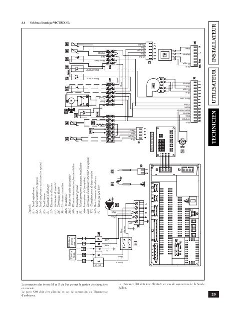
3.1 Schéma électrique VICTRIX <strong>50</strong>.Légende:B1 - Sonde refoulementB2 - Sonde sanitaire (en option)B4 - Sonde température extérieure (en option)B5 - Sonde retourE1 - Électrode d’allumageE2 - Électrode de détectionE4 - Thermostat de sécuritéE6 - Thermostat fuméesM1 - Circulateur chaudièreM20 - VentilateurM30 - Vanne trois voies (en option)R8 - Résistance désactivation fonction ballonS1 - Interrupteur généralS5 - Microinterrupteur pressostat installationS16 - Interrupteur été (en option)S20 - Thermostat d’ambiance ON/OFF (en option)T10 - Transformateur de basse tensionX40 - Pont thermostat d’ambianceY1 - Vanne gaz (24 Vcc)INSTALLATEURTECHNICIENUTILISATEURLa connexion des bornes M et O du Bus permet la gestion des chaudièresen cascade.Le pont X40 doit être éliminé en cas de connexion du Thermostatd’ambiance.La résistance R8 doit être éliminée en cas de connexion de la SondeBallon.29