TA MS 400V / 230V - tormatic
TA MS 400V / 230V - tormatic
TA MS 400V / 230V - tormatic
- No tags were found...

You also want an ePaper? Increase the reach of your titles
YUMPU automatically turns print PDFs into web optimized ePapers that Google loves.
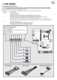
GBInstallation0123Required toolsInstalling the control unitOpening the control unit coverConnectionsDesignation:J1J4External operation (remote control)Emergency stopJ5 Sensor door openJ6 Wheel chockJ7 Key switchJ10 Connection of add-on controlsJ13 Membrane keypadJ14 Communication interfaceX1 Mains connectionX2 Mains output L, N (500 W / 230 V)X3 Protective conductor contactX5X6X8Floating relay output 1Floating relay output 2Hydraulic valves and sensors4 Mains connectionThe control unit comes ready-wired with a 16A CEEphase-changer plug and approx. 1 m of cable (see4a) .!Wrong connection of mains voltage candestroy the control.Observe rotating field.Mains isolatorA mains isolator is provided fordisconnection of all poles of the mainsvoltage. Secure the mains isolator againstunauthorised use during maintenanceor repair.10 Floating relay outputConnect the visual and audible warning signals to X5and dock light to X6.11 External operating panelAn external operating panel (remote control) can beconnected with J1 for operating the dock leveller.The dock leveller must remain visible fromthe place of operating it. It must bepossible to switch off the panel with anemergency-OFF button that interrupts thesafety circuit at J4.Programming the control unitProgramming is menu-driven. Make all settings asshown in the schematic.Protected settings are identified by the letter L in thedisplay and access to the menu is barred. To releasethe menu, the release signal must be sent with theinfrared control.Hydraulic motor overcurrent (menu 10)If the set overcurrent is exceeded, the control willswitch off the pump.Display of the actual valueLift the dock leveller until the pressure relief valvetrips. Now keep button in menu 10 pressed for 5sec; the value achieved for the motor current will nowbe displayed. Make sure that the set value is largerthan the one displayed.Automatic time (menu 13)When the return button is pressed, the dock levelleris lifted for the time set and then lowered safely tozero position.Connection of hydraulic motor5 Valve connectionA sensor and limit switch for the automatic returnfunction can be installed beside the valveconnection.6 Emergency stop buttonRemove the jumper and connect the emergencystopbutton. Pressing the emergency stop buttonstops the dock leveller, no free floating position.7 Connection for sensor door openFor safety reasons, the dock leveller can only beoperated when the door is open.Possible connections:7a Mechanical limit switch7b Inductive proximity switch orbr - brownbk - blackbl - blue8 Wheel chockPossible connection of a wheel chock sensor.Selection of menu 15 = 1.The dock leveller can only lift and extend when thewheel chock is applied.br - browngr - greybk - black9 Key switch connectionWhen using a key switch, the desired function inmenu 50 should be selected.Automatic retraction time (menu 14)When button is released, the lip retracts for the settime to correct the position.Initial start-upTo ensure safe operation of the dock leveller the firststart-up should be performed by instructedpersonnel.- Switch on the mains isolator.- Make a trial run during which you performyou all control functions.If all control operations work smoothly, the dockleveller is ready for use.