

Guide d'exploitation ATV62
Guide d'exploitation ATV62
Guide d'exploitation ATV62

Create successful ePaper yourself
Turn your PDF publications into a flip-book with our unique Google optimized e-Paper software.
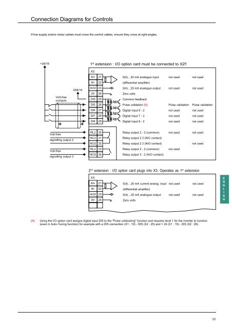
Connection Diagrams for ControlsIf line supply and/or motor cables must cross the control cables, ensure they cross at right-angles.+24/151 st extension : I/O option card must be connected to X2!!X2:AI+210(4)…20 mA analogue input not used not usedAI- 22(differential amplifier)Volt-freecontactsDIS/10AO2 230V 24DIS 25DI5 260(4)…20 mA analogue output not used not usedZero voltsCommon feedbackPulse validation (1) Pulse validation Pulse validationDI6 27Digital input 6 - 2 not used not usedDI7 28Digital input 7 - 2 not used not usedDI8 29Digital input 8 - 2 not used not usedVolt-freesignalling output 2Volt-freesignalling output 3RL2 30NC2 31NO2 32RL3 33NO3 34Relay output 2 - 2 (common) not used not usedRelay output 2 2 (N/C contact)Relay output 2 2 (N/O contact)not usedRelay output 2 - 2 (common) not usedRelay output 3 - 2 (N/O contact)2 nd extension : I/O option card plugs into X3. Operates as 1 st extensionX3:AI+ 21AI- 22AO2 230V 240(4)…20 mA current analog. input not used not used(differential amplifier)0(4)…20 mA analogue output not used not usedZero voltsENGLISH(1) Using the I/O option card assigns digital input DI5 to the "Pulse unblocking" function and requires level 1 for the inverter to function(even in Auto-Tuning function) for example with a DIS connection (X1 : 10) - DIS (X2 : 25) and + 24 (X1 : 15) - DI5 (X2 : 26).33


