<strong>Pump</strong> Model Number:<strong>Pump</strong> Serial Number:Control Model Number:Dealer:Dealer Phone No.Date of Purchase:Owner’s InformationInstallation:Table of ContentsSUBJECTPAGESafety Instructions....................................................................3Installation................................................................................3Suction Piping..........................................................................3Discharge Piping......................................................................3Water Heaters..........................................................................3Wiring......................................................................................3Installation with Positive Suction Head...................................4Operation.................................................................................4Priming Instructions.............................................................4Maintenance............................................................................4Mechanical Seal...................................................................4Replacement of Mechanical Seal.........................................4Locating Trouble......................................................................5If Your Unit Fails to Function Properly................................5If <strong>Pump</strong> Runs But Does Not Deliver Water.........................5Vacuum Gauge Method for Testing Suction........................6If <strong>Pump</strong> Delivers Water But Pressure Switch Does NotStop <strong>Pump</strong> When Water is Not Being Used........................6If, after <strong>Pump</strong> has been In Service For Some Time,It <strong>Pump</strong>s Water But Does Not Shut Off When WaterIs Not Being Used................................................................6If pump Starts and Stops Frequently When Water isNot Being Used....................................................................6Air Volume Control.................................................................7Why it is Necessary..............................................................7How it Works.......................................................................7Water Logged (Air Cushioning Chamber) Casing...............7If Water Leaks Around Air Volume Control........................7Seasonal Service.......................................................................7To Take Out of Service.........................................................7To Place <strong>Pump</strong> Back in Service............................................7Repair Parts..............................................................................9Limited Warranty...................................................................102
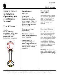
SAFETY <strong>INSTRUCTION</strong>STO AVOID SERIOUS OR FATAL PERSONAL INJURYOR MAJOR PROPERTY DAMAGE, READ ANDFOLLOW ALL SAFETY <strong>INSTRUCTION</strong>S IN <strong>MANUAL</strong>AND ON PUMP.THIS <strong>MANUAL</strong> IS INTENDED TO ASSIST IN THEINSTALLATION AND OPERATION OF THIS UNITAND MUST BE KEPT WITH THE PUMP.This is a SAFETY ALERT SYMBOL.When you see this symbol on the pump orin the manual, look for one of the followingsignal words and be alert to the potential forpersonal injury or property damage.DANGER Warns of hazards that WILL cause seriouspersonal injury, death or major propertydamage.WARNING Warns of hazards that CAN cause seriouspersonal injury, death or major propertydamage.CAUTIONWarns of hazards that CAN cause personalinjury or property damage.NOTICE: INDICATES SPECIAL <strong>INSTRUCTION</strong>SWHICH ARE VERY IMPORTANT ANDMUST BE FOLLOWED.THOROUGHLY REVIEW ALL <strong>INSTRUCTION</strong>S ANDWARNINGS PRIOR TO PERFORMING ANY WORKON THIS PUMP.MAINTAIN ALL SAFETY DECALS.INSTALLATIONUnit should be mounted on a firm, level base and in aconvenient location, where it is protected from freezing. Unitshould not be completely enclosed as adequate clean air forventilation is necessary for proper operation of motor and toprevent overheating.If unit is installed in kitchen, sink cabinet, playroom or otherplace where moisture might be objectionable it is suggestedthat a pan be located under the entire unit to catch thecondensation drip that may collect on the unit during humidweather.PrimingPlugPressureSwitchAirValveCheckValveDrain PlugAir Volume ControlGateValveDischargeSuctionFigure 1SUCTION PIPINGWARNING Do not remove the suction check valve evenis a foot valve is used on other end of suctionpipe. Run suction pipe to well, connect-ing pump end to suction check valve on pump. Observe thefollowing instruction:1. Use adequate pipe sizes, never smaller then ¾" exceptunder positive suction head (see page 4). Where totalpipe length between pump and source of supply is over25 ft., use the following table to determine pipe size. Anincreaser fitting will be required at pump.Total Length ofSuction Pipe Between<strong>Pump</strong> And WellSizeSuction PipeUp to 26' to 101' to25' 100' 300'¾" 1" 1¼"Note: The total suction lift, which includes the verticaldistance between the pumping level of the water and thepump plus the friction loss in the pipe should not exceed25 feet.2. All piping or tubing should be inspected to make sureit contains no scale, dirt or other foreign material thatmight impair operation of pump.3. All joints must be air tight. A good pipe compoundshould be used.4. A union should be installed in the suction line close to thepump. Packed unions are preferable. If ground unionsare used they must be carefully aligned.5. On suction lines 50 feet or more in length, a foot valvecan be used to lessen priming time. Install a tee in thesuction line for priming. When a foot valve is used,prime pump through priming opening and suction linethrough opening in tee.6. Dug or drilled wells should be vented.DISCHARGE PIPINGConnect house service pipe to ¾" discharge opening. A gatevalve in the discharge line close to the pump will facilitateworking on pump without draining entire house system.WATER HEATERSA check valve should be installed close to pump in thedischarge line between pump and water heater or otherheating appliance to prevent hot water from entering pump.Be sure water heater or other heating device is equippedwith a temperature and pressure relief valve.WIRINGWARNING Do not run pump until it has been filled tothe priming opening with clear water (seePRIMING, page 4).Standard motors furnished are 115/230V, single phase,60 Hz, A.C. motors.Dual voltage motors will be wired for 115 volts. They canbe changed to 230 volts by following the instructions on themotor or on the nameplate.1. Use wire of sufficient size to maintain adequate voltageat motor terminals while pump is running. Voltagevariations of plus or minus 10% from nameplate valueare allowable at motor terminals.2. Motor circuits should be properly protected accordingto NEC, CSA, state, provincial and local electric wiringcodes.3