MODUCONTROL
MODUCONTROL
MODUCONTROL

Create successful ePaper yourself
Turn your PDF publications into a flip-book with our unique Google optimized e-Paper software.
46<br />
User interface and parameter visualisations<br />
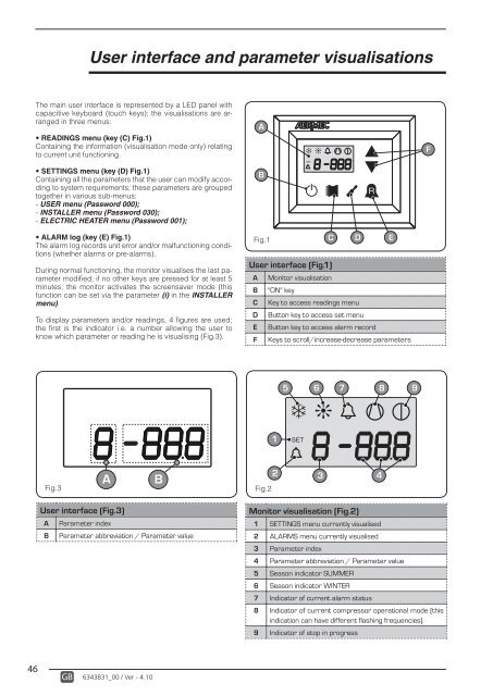
The main user interface is represented by a LED panel with<br />
capacitive keyboard (touch keys); the visualisations are arranged<br />
in three menus:<br />
READINGS menu (key (C) Fig.1)<br />
Containing the information (visualisation mode only) relating<br />
to current unit functioning.<br />
SETTINGS menu (key (D) Fig.1)<br />
Containing all the parameters that the user can modify according<br />
to system requirements; these parameters are grouped<br />
together in various sub-menus:<br />
- USER menu (Password 000);<br />
- INSTALLER menu (Password 030);<br />
- ELECTRIC HEATER menu (Password 001);<br />
ALARM log (key (E) Fig.1)<br />
The alarm log records unit error and/or malfunctioning conditions<br />
(whether alarms or pre-alarms).<br />
During normal functioning, the monitor visualises the last parameter<br />
modifi ed; if no other keys are pressed for at least 5<br />
minutes, the monitor activates the screensaver mode (this<br />
function can be set via the parameter (i) in the INSTALLER<br />
menu).<br />
To display parameters and/or readings, 4 fi gures are used;<br />
the fi rst is the indicator i.e. a number allowing the user to<br />
know which parameter or reading he is visualising (Fig.3).<br />
Fig.3<br />
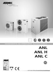
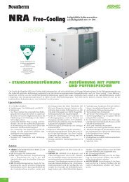
User interface (Fig.3)<br />
A B<br />
A Parameter index<br />
B Parameter abbreviation / Parameter value<br />
GB 6343831_00 / Ver - 4.10<br />
A<br />
B<br />
Fig.1<br />
dj<br />
SET<br />
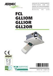
User interface (Fig.1)<br />
A Monitor visualisation<br />
B "ON" key<br />
C Key to access readings menu<br />
D Button key to access set menu<br />
E Button key to access alarm record<br />
F Keys to scroll/increase-decrease parameters<br />
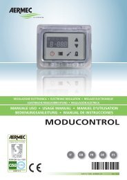
Fig.2<br />
1<br />
SET<br />
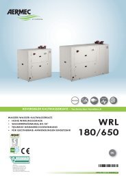
Monitor visualisation (Fig.2)<br />
R<br />
C D E<br />
5 6<br />
dj<br />
7 8 9<br />
2 3<br />
1 SETTINGS menu currently visualised<br />
2 ALARMS menu currently visualised<br />
3 Parameter index<br />
4 Parameter abbreviation / Parameter value<br />
5 Season indicator SUMMER<br />
6 Season indicator WINTER<br />
7 Indicator of current alarm status<br />
8 Indicator of current compressor operational mode (this<br />
indication can have different flashing frequencies).<br />
9 Indicator of stop in progress<br />
4<br />
F