MODUCONTROL
MODUCONTROL
MODUCONTROL

You also want an ePaper? Increase the reach of your titles
YUMPU automatically turns print PDFs into web optimized ePapers that Google loves.
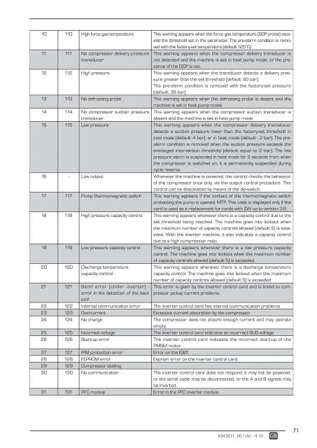
10 110 High force gas temperature This warning appears when the force gas temperature (SGP probe) exceeds<br />
the threshold set in the parameter. The pre-alarm condition is removed<br />
with the factory-set temperature (default 125°C).<br />
11 111 No compressor delivery pressure<br />
transducer<br />
This warning appears when the compressor delivery transducer is<br />
not detected and the machine is set in heat pump mode, or the presence<br />
of the DCP is set.<br />
12 112 High pressure This warning appears when the transducer detects a delivery pressure<br />
greater than the set threshold (default: 40 bar).<br />
The pre-alarm condition is removed with the factory-set pressure<br />
(default: 38 bar).<br />
13 113 No defrosting probe This warning appears when the defrosting probe is absent and the<br />
machine is set in heat pump mode.<br />
14 114 No compressor suction pressure<br />
transducer<br />
This warning appears when the compressor suction transducer is<br />
absent and the machine is set in heat pump mode.<br />
15 115 Low pressure This warning appears when the compressor delivery transducer<br />
detects a suction pressure lower than the factory-set threshold in<br />
cool mode (default: 4 bar), or in heat mode (default : 2 bar). The prealarm<br />
condition is removed when the suction pressure exceeds the<br />
envisaged intervention threshold (default equal to 2 bar). The low<br />
pressure alarm is suspended in heat mode for 3 seconds from when<br />
the compressor is switched on; it is permanently suspended during<br />
cycle reverse.<br />
16 - Low output Whenever the machine is powered, the control checks the behaviour<br />
of the compressor once only, via the output control procedure. This<br />
control can be deactivated by means of the dip-switch.<br />
17 117 Pump thermomagnetic switch This warning appears if the contact of the thermomagnetic switch<br />
protecting the pump is opened. MTP. This code is displayed only if the<br />
card is used as a replacement for cards with SW up to version 3.6.<br />
18 118 High pressure capacity control This warning appears whenever there is a capacity control due to the<br />
set threshold being reached. The machine goes into lockout when<br />
the maximum number of capacity controls allowed (default 5) is exceeded.<br />
With the inverter machine, it also indicates a capacity control<br />
due to a high compression ratio.<br />
19 119 Low pressure capacity control This warning appears whenever there is a low pressure capacity<br />
control. The machine goes into lockout when the maximum number<br />
of capacity controls allowed (default 5) is exceeded.<br />
20 120 Discharge temperature<br />
capacity control<br />
21 121 Bemf error (chiller inverter) -<br />
error in the detection of the back<br />
emf<br />
This warning appears whenever there is a discharge temperature<br />
capacity control. The machine goes into lockout when the maximum<br />
number of capacity controls allowed (default 5) is exceeded.<br />
This error is given by the inverter control card and is linked to compressor<br />
pickup current problems.<br />
22 122 Internal communication error The inverter control card has internal communication problems.<br />
23 123 Overcurrent Excessive current absorption by the compressor.<br />
24 124 No charge The compressor does not absorb enough current and may operate<br />
empty.<br />
25 125 Incorrect voltage The inverter control card indicates an incorrect BUS voltage.<br />
26 126 Start-up error The inverter control card indicates the incorrect start-up of the<br />
PMSM motor.<br />
27 127 IPM protection error Error on the IGBT.<br />
28 128 EEPROM error Eeprom error on the inverter control card.<br />
29 129 Compressor stalling<br />
30 130 No communication The inverter control card does not respond; it may not be powered,<br />
or the serial cable may be disconnected, or the A and B signals may<br />
be inverted.<br />
31 131 PFC module Error in the PFC inverter module.<br />
6343831_00 / Ver - 4.10<br />
GB<br />
71