Notice technique – Automatisme PP60 pour porte ... - Wayne Dalton
Notice technique – Automatisme PP60 pour porte ... - Wayne Dalton
Notice technique – Automatisme PP60 pour porte ... - Wayne Dalton

You also want an ePaper? Increase the reach of your titles
YUMPU automatically turns print PDFs into web optimized ePapers that Google loves.
22<br />
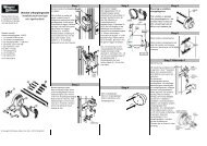
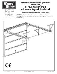
Wiring the Lighted Door Control Button<br />
(Optional)<br />
Locate any Wall Mounted Door Control where the garage door is visible, away<br />
from door and door hardware, at a minimum height of 1.5m. fasten the child<br />
warning label on the wall near the Door Control.<br />
There are 2 screw terminals (1) on the back of the Door Control (2). Strip about<br />
6mm of insulation from bell wire (4). Separate wires enough to connect the white/red<br />
wire to terminal screw 1 and the white wire to terminal screw (1)<br />
Lighted Door Control Button: Fasten to an inside garage wall with sheet metal<br />
screws (3) provided with Lighted Push Button. Drill 4mm holes and use anchors (6)<br />
if installing into drywall or concrete. A convenient place is beside the service door<br />
and out of reach of children.<br />
Run the bell wire up the wall and across the ceiling to the garage door opener. Use<br />
insulated staples (5) to secure wire.<br />
The opener Quick-Connect Terminals (7) are located in the recess next to the learn<br />
button on the left side panel. Insert bell wire into holes in the Quick Connect<br />
Terminals as follows: Red/White to Red and White to White.<br />
23<br />
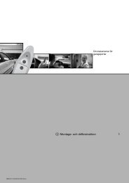
Install Protector System<br />
(Optional) <strong>–</strong> (See accessories)<br />
After opener has been installed and adjusted, The Protector System accessory<br />
can be installed. Instructions are included with this optional device.<br />
The Protector System provides an additional measure of safety against a<br />
small child being caught under a garage door.<br />
It uses an invisible beam which, when broken by an obstruction, causes a closing<br />
door to open and prevents an open door from closing and is strongly recommended<br />
for homeowners with young children.<br />
114A3371 - 2nd edition EN<br />
24<br />
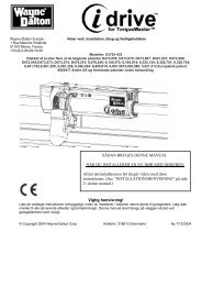
Accessories (optional)<br />
- 3-channel mini remote control<br />
- Keypad<br />
- Outside quick release<br />
- Photocells “Protector System”<br />
Specifications<br />
Input Voltage . . . . . . . . . . . . . . .230 VAC 50/60 Hz<br />
Max. Pull force . . . . . . . . . . . . . .600N<br />
Rated Power Input . . . . . . . . . . .85 Watts<br />
Rated Load . . . . . . . . . . . . . . . .3.0 Nm<br />
Standby Power . . . . . . . . . . . . . .9 Watts<br />
Max. Door Weight . . . . . . . . . . .60kg<br />
Motor<br />
Type . . . . . . . . . . . . . . . . . . . . . .63:1 Worm Gear Reduction<br />
Volts . . . . . . . . . . . . . . . . . . . . . .24VDC<br />
Drive Mechanism<br />
Length of Travel . . . . . . . . . . . . .2.3M<br />
Travel Rate . . . . . . . . . . . . . . . .8cm/sec<br />
Lamp . . . . . . . . . . . . . . . . . . . . .24V 21 Watts<br />
Safety<br />
Electronic . . . . . . . . . . . . . . . . . .Auto-Force Adjustment<br />
Electrical . . . . . . . . . . . . . . . . . .Thermal Fuse in Transformer<br />
Limit Adjustment . . . . . . . . . . . . .Manual<br />
Dimension<br />
Length (Overall) . . . . . . . . . . . . .2.75m<br />
Headroom Required . . . . . . . . . .30mm<br />
Hanging Weight . . . . . . . . . . . . .9kg<br />
Receiver Code Registers<br />
Rolling Code . . . . . . . . . . . . . . .8<br />
Operating Frequency . . . . . . . . .433.92MHz