ZT 71 ZT 72 - Cyclon Engineering
ZT 71 ZT 72 - Cyclon Engineering
ZT 71 ZT 72 - Cyclon Engineering

You also want an ePaper? Increase the reach of your titles
YUMPU automatically turns print PDFs into web optimized ePapers that Google loves.
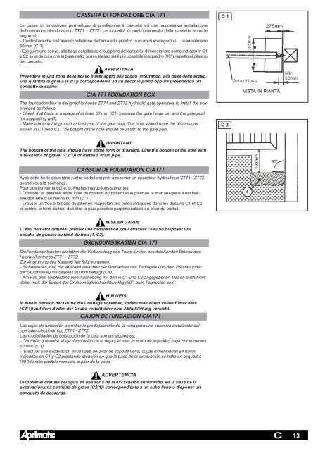
CASSETTA DI FONDAZIONE CIA 1<strong>71</strong> C 1<br />
Le casse di fondazione permettono di predisporre il cancello ad una successiva installazione<br />
dell’operatore oleodinamico <strong>ZT</strong><strong>71</strong> - <strong>ZT</strong><strong>72</strong>. Le modalità di posizionamento della cassetta sono le<br />
seguenti:<br />
- Controllare che tra l’asse di rotazione dell’anta ed il pilastro (o muro di sostegno) vi siano almeno<br />
60 mm (C 1).<br />
- Eseguire uno scavo, alla base del pilastro di supporto del cancello, dimensionato come indicato in C1<br />
e C2 avendo cura che la base dello scavo stesso sia il più possibile in squadro (90°) rispetto al pilastro<br />
del cancello.<br />
AVVERTENZA<br />
Prevedere in una zona dello scavo il drenaggio dell’acqua interrando, alla base dello scavo,<br />
una quantità di ghiaia (C2(1)) corrispondente ad un secchio pieno oppure prevedendo un<br />
condotto di scario.<br />
CIA 1<strong>71</strong> FOUNDATION BOX<br />
The foundation box is designed to house <strong>ZT</strong><strong>71</strong> and <strong>ZT</strong><strong>72</strong> hydraulic gate operators to install the box<br />
proceed as follows:<br />
- Cheek that there is a space of at least 60 mm (C1) between the gate hinge pin and the gate post<br />
(or supporting wall).<br />
- Make a hole in the ground at the base of the gate post. The hole should have the dimensions<br />
shown in C1 land C2. The bottom of the hole should be at 90° to the gate post.<br />
IMPORTANT<br />
The bottom of the hole should have some form of drainage. Line the bottom of the hole with<br />
a bucketful of gravel (C2(1)) or install a drain pipe.<br />
CAISSON DE FOUNDATION CIA1<strong>71</strong><br />
Avec cette boîte sous terre, votre portail est prêt à recevoir un opérateur hydraulique <strong>ZT</strong><strong>71</strong> - <strong>ZT</strong><strong>72</strong>,<br />
quand vous le souhaitez.<br />
Pour positionner la boîte, suivre les instructions suivantes:<br />
- Contrôler la distance entre l’axe de rotation du battant et le pilier ou le mur auxquels il est flxé:<br />
elle doit être d’au moins 60 mm (C 1).<br />
- Creuser un trou à la base du pilier en respectant les cotes indiquées dans les dessins C1 et C2<br />
ci-contre; le fond du trou doit être le plus possible perpendiculaire au pilier du portail.<br />
MISE EN GARDE<br />
L’ eau doit être drainée: prévoir une canalisation pour évacuer l’eau ou disposer une<br />
couche de gravier au fond du trou (1, C2).<br />
GRÜNDUNGSKASTEN CIA 1<strong>71</strong><br />
DieFundamentkästen gestatten die Vorbereitung des Tores für den anschließenden Einbau des<br />
Hydraulikantriebs <strong>ZT</strong><strong>71</strong> - <strong>ZT</strong><strong>72</strong>.<br />
Zur Anordnung des Kastens wie folgt vorgehen:<br />
- Sicherstellen, daß der Abstand zwischen der Drehachse des Torflügels und dem Pfosten (oder<br />
der Stützmauer) mindestens 60 mm beträgt (C1).<br />
- Am Fuß des Torpfostens eine Aushebung mit den in C1 und C2 angegebenen Maßen ausführen;<br />
dabei muß der Boden der Grube möglichst rechtwinklig (90°) zum Torpfosten sein.<br />
HINWEIS<br />
In einem Bereich der Grube die Drainage vorsehen, indem man einen vollen Eimer Kies<br />
(C2(1)) auf dem Boden der Grube verteilt oder eine Abflußleitung vorsieht.<br />
CAJON DE FUNDACION CIA1<strong>71</strong><br />
Las cajas de fundación permiten la predisposición de la verja para una sucesiva instalación del<br />
operador oleodinámico <strong>ZT</strong><strong>71</strong> - <strong>ZT</strong><strong>72</strong>.<br />
Las modalidades de colocación de la caja son las siguientes:<br />
- Controlar que entre el eje de rotación de la hoja y el pilar (o muro de sujeción) haya por lo menos<br />
60 mm. (C1).<br />
- Efectuar una excavación en la base del pilar de soporte verja, cuyas dimensiones se hallan<br />
indicadas en C1 y C2 prestando atención en que la base de la excavación se halle en esquadra<br />
(90°) lo más posible respecto al pilar de la verja.<br />
ADVERTENCIA<br />
Disponer el drenaje del agua en una zona de la excavación enterrando, en la base de la<br />
excavación,una cantidad de grava (C2(1)) correspondiente a un cubo Ileno o disponer un<br />
conducto de descarga.<br />
C 2<br />
4<br />
C<br />
13