
Create successful ePaper yourself
Turn your PDF publications into a flip-book with our unique Google optimized e-Paper software.
6<br />
<strong>GAMING</strong> <strong>SERIES</strong> <br />
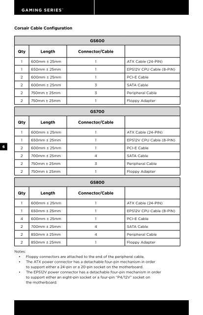
<strong>Corsair</strong> Cable Configuration<br />
GS600<br />
Qty Length Connector/Cable<br />
1 600mm ± 25mm 1 ATX Cable (24-PIN)<br />
1 650mm ± 25mm 1 EPS12V CPU Cable (8-PIN)<br />
2 600mm ± 25mm 1 PCI-E Cable<br />
2 600mm ± 25mm 3 SATA Cable<br />
2 750mm ± 25mm 3 Peripheral Cable<br />
2 750mm ± 25mm 1 Floppy Adapter<br />
GS700<br />
Qty Length Connector/Cable<br />
1 600mm ± 25mm 1 ATX Cable (24-PIN)<br />
1 650mm ± 25mm 1 EPS12V CPU Cable (8-PIN)<br />
2 600mm ± 25mm 1 PCI-E Cable<br />
2 700mm ± 25mm 4 SATA Cable<br />
2 750mm ± 25mm 3 Peripheral Cable<br />
2 750mm ± 25mm 1 Floppy Adapter<br />
GS800<br />
Qty Length Connector/Cable<br />
1 600mm ± 25mm 1 ATX Cable (24-PIN)<br />
1 650mm ± 25mm 1 EPS12V CPU Cable (8-PIN)<br />
4 600mm ± 25mm 1 PCI-E Cable<br />
2 700mm ± 25mm 4 SATA Cable<br />
2 850mm ± 25mm 4 Peripheral Cable<br />
2 850mm ± 25mm 1 Floppy Adapter<br />
Notes:<br />
• Floppy connectors are attached to the end of the peripheral cable.<br />
• The ATX power connector has a detachable four-pin mechanism in order<br />
to support either a 24-pin or a 20-pin socket on the motherboard.<br />
• The EPS12V power connector has a detachable four-pin mechanism in order<br />
to support either an eight-pin socket or a four-pin “P4/12V” socket on<br />
the motherboard.<br />
Installation<br />
Before proceeding with installation, please read this manual in its entirety.<br />
<strong>GAMING</strong> <strong>SERIES</strong> <br />
Step A: Removing your existing power supply<br />
If you are building a new system, skip to Step B.<br />
1. Disconnect the AC power cord from your wall outlet or UPS and from the existing<br />
power supply.<br />
2. Disconnect all the power cables from your video card, motherboard and all other<br />
peripherals.<br />
3. Follow the directions in your chassis manual and uninstall your existing<br />
power supply.<br />
4. Proceed to Step B.<br />
Step B: Installing the <strong>Corsair</strong> Gaming Series power supply<br />
1. Make sure the power supply’s AC power cable is not connected.<br />
2. Follow the directions in your chassis manual and install the power supply with<br />
the screws provided.<br />
3. Connect the main 24-pin power cable. The main 24-pin power cable has a<br />
detachable 4-pin mechanism in order to support either a 24-pin or a 20-pin<br />
socket on the motherboard.<br />
a. If your motherboard has a 24-pin socket, you may connect the 24-pin main<br />
power cable from the power supply directly to your motherboard.<br />
b. If your motherboard has a 20-pin socket, you must detach the four-pin<br />
cable from the 24-pin connector, and then plug the 20-pin cable onto your<br />
motherboard without connecting the four-pin connector.<br />
4. Connect the eight-pin +12V (EPS12V) cable.<br />
a. If your motherboard has an eight-pin +12V socket, connect the eight-pin<br />
cable directly to your motherboard.<br />
b. If your motherboard has a four-pin socket, detach the four-pin from the<br />
eight-pin cable, and then plug this four-pin cable directly to your motherboard.<br />
WARNING: The detachable four-pin from the 24-pin main connector is not a “P4” or “+12V”<br />
connector. Serious damage can be caused if you use it in place of a “P4” or “+12V” connector.<br />
5. Connect the peripheral cables, PCI-Express cables, and SATA cables.<br />
a. Connect the peripherals cables to your hard drive and CD-ROM/DVD-ROM<br />
power sockets.<br />
b. Connect the SATA cables to your SATA SSD or hard drive’s power sockets.<br />
c. Connect the PCI-Express cables to the power sockets of your PCI-Express<br />
video cards if required.<br />
d. Connect the peripheral cables to any peripherals requiring a small<br />
4-pin connector.<br />
e. Make sure all the cables are tightly connected.<br />
6. Connect the AC power cord to the power supply and turn it on by pushing the<br />
switch to the ON position (marked with “I”).<br />
Congratulations! You have completed installation of your new <strong>Corsair</strong> Gaming Series power<br />
supply and your system is ready to go!<br />
Fan LED Control<br />
LED output is controlled with a button near the power switch. On the GS600, tap the button<br />
to turn the blue LEDs on or off. On the GS700 and GS800, tap the button to cycle between<br />
red, white, blue, and off.<br />
7