Manuale Centrale radio Supercom 646 - Contabilizzazione del calore
Manuale Centrale radio Supercom 646 - Contabilizzazione del calore
Manuale Centrale radio Supercom 646 - Contabilizzazione del calore

Create successful ePaper yourself
Turn your PDF publications into a flip-book with our unique Google optimized e-Paper software.
<strong>Manuale</strong><br />
<strong>Centrale</strong> <strong>radio</strong><br />
<strong>Supercom</strong> <strong>646</strong><br />
Edizione: Rev. 18-03-2010<br />
Documento: Handbuch <strong>Supercom</strong> <strong>646</strong> R+W rev. 18-03-2010<br />
Costruttore:<br />
Sontex SA<br />
2605 Sonceboz, Schweiz<br />
Telefon: +41 32 488 30 00<br />
Fax: +41 32 488 30 01<br />
Email: sontex@sontex.ch<br />
Internet: www.sontex.ch<br />
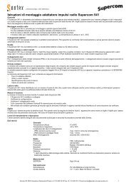
Distributore in Italia: Enercom srl,Via G. Ferraris 5b,42100 Reggio<br />
Emilia.Tel.+390522 554012 Fax +390522331705<br />
Mail:assistenza@enercomit.com<br />
Modifiche tecniche senza preavviso e con riserva <strong>del</strong> costruttore
Indice<br />
1. Generale .................................................................................................. 4<br />
1.1 Introduzione .................................................................................................................. 4<br />
1.2 Campo di utilizzo <strong>del</strong>la centrale <strong>radio</strong> ............................................................................ 4<br />
2. Contenuto <strong>del</strong>la fornitura ....................................................................... 5<br />
3. Installazione <strong>del</strong>la centrale <strong>radio</strong> ........................................................... 5<br />
3.1 Montaggio <strong>del</strong>la centrale <strong>radio</strong> ...................................................................................... 5<br />
3.1.1 Montaggio a parete ................................................................................................................... 5<br />
3.2 Alimentazione ................................................................................................................ 5<br />
3.2.1 Attivazione <strong>del</strong>l´alimentazione .................................................................................................. 5<br />
3.2.2 Attivazione <strong>del</strong>la batteria sulla scheda principale ...................................................................... 5<br />
3.2.3 Batteria-Modulorete per 52 registrazioni all´anno ...................................................................... 5<br />
3.2.4 Modulo rete .............................................................................................................................. 5<br />
3.2.5 Modulo GSM/GPRS ................................................................................................................ 6<br />
3.2.6 Modulo M-Bus ......................................................................................................................... 6<br />
3.3 Chiudere e sigillare l´apparecchio ................................................................................. 6<br />
3.4 Parametraggio <strong>del</strong>la centrale <strong>radio</strong>................................................................................ 6<br />
3.4.1 Accendere la centrale <strong>radio</strong> con il Software Tools<strong>646</strong> .............................................................. 6<br />
4. Memorizzazione die dati ed intervalli <strong>del</strong>la apparecchiature<br />
<strong>radio</strong> ......................................................................................................... 7<br />
4.1 Piano lettura <strong>radio</strong> ......................................................................................................... 7<br />
4.2 Memorizzazione die dati ................................................................................................ 8<br />
5. Descrizione degli LED ............................................................................ 9<br />
5.1 Indicatore LED .............................................................................................................. 9<br />
5.2 Problemi con l´alimentazione ...................................................................................... 10<br />
5.2.1 Alimentazione staccata oppure batteria debole:...................................................................... 10<br />
5.2.2 Batteri per l´alimentazione oppure batteria Backup scarica:.................................................... 10<br />
6. Indicazioni generali .............................................................................. 11<br />
6.1.1 Alimentazione staccata oppure batteria scarica ...................................................................... 11<br />
6.1.2 Smaltimento batteria ........................................................... Fehler! Textmarke nicht definiert.<br />
6.1.3 Collegamento elettrico modulo rete ........................................................................................ 11<br />
6.1.4 Indicazioni di sicurezza ........................................................................................................... 11<br />
6.2 Sigillo…. ...................................................................................................................... 11<br />
6.3 Dati tecnici ................................................................................................................... 12<br />
6.4 Dimensoni ................................................................................................................... 13<br />
7. M-Bus Protocollo di comunicazione ................................................... 14<br />
7.1 Introduzione ................................................................................................................ 14<br />
7.2 Divisione <strong>del</strong>la memoria <strong>del</strong>la centrale ........................................................................ 14<br />
7.3 Principio di lettura ........................................................................................................ 14<br />
7.3.1 Descrizione per la lettura <strong>del</strong>la configurazione e <strong>del</strong>la lista apparecchiature <strong>del</strong>la<br />
centrale <strong>radio</strong> .......................................................................................................................... 15<br />
7.3.2 ARichiesta die dati letti e memorizzati <strong>del</strong>le apparecchiature <strong>radio</strong> ......................................... 20<br />
<strong>Manuale</strong> <strong>Supercom</strong> <strong>646</strong> 12042010<br />
2
7.4 Principio di scrittura <strong>del</strong>la centrale <strong>radio</strong> ...................................................................... 21<br />
7.4.1 Modifica <strong>del</strong>la configurazione <strong>del</strong>la centrale <strong>radio</strong> ................................................................... 21<br />
7.4.1 Password <strong>del</strong>la centrale <strong>radio</strong> ................................................................................................. 22<br />
7.4.2 Aggiungere un apparecchio nella lista <strong>del</strong>le apparecchiature.................................................. 22<br />
7.4.3 Modifica <strong>del</strong>la lista apparecchiature ........................................................................................ 22<br />
8. Utilizzo ................................................................................................... 23<br />
8.1 Attualizzare il Firmware .............................................................................................. 23<br />
9. Allegato A .............................................................................................. 24<br />
9.1 Leggere la configurazione nella centrale <strong>radio</strong> ............................................................ 24<br />
9.2 Leggere <strong>del</strong>la liste <strong>del</strong>le apparecchiature memorizzate nella centrale <strong>radio</strong> ............... 25<br />
9.3 Leggere i dati <strong>del</strong>le apparecchiature lette e memorizzate nella centrale <strong>radio</strong> ............ 26<br />
10. Allegato B .............................................................................................. 27<br />
10.1 Principio di scrittura e configurazione nella centrale <strong>radio</strong> ........................................... 27<br />
<strong>Manuale</strong> <strong>Supercom</strong> <strong>646</strong> 12042010<br />
3
1. Generale<br />
1.1 Introduzione<br />
In questo manuale viene descritta la funzione e l´utilizzo <strong>del</strong> <strong>Supercom</strong> <strong>646</strong>. Il manuale<br />
e´destinato a tecnici.<br />
1.2 Campo di utilizzo <strong>del</strong>la centrale <strong>radio</strong><br />
La centrale radia <strong>Supercom</strong> <strong>646</strong> concentra i dati che riceve via <strong>radio</strong> dalle apparecchiature dotate<br />
con il sistema <strong>radio</strong>. La centrale <strong>radio</strong> <strong>Supercom</strong> puo´essere letta tramite USB oppure interfaccia<br />
RS232 , ottico, tramite M-Bus oppure GSM/GPRS. Possono essere lette le seguenti apparecchiature<br />
Sontex tramite <strong>radio</strong>:<br />
Ripartitore <strong>radio</strong> 502s / 552 / 556<br />
Distributore acqua 590<br />
Contatore di <strong>calore</strong> compatto Supercal 539 con l´opzione <strong>radio</strong><br />
Contatore di <strong>calore</strong> Superstatic 440 con l´opzione <strong>radio</strong><br />
Unita´di calcolo Supercal 531 con l´opzione <strong>radio</strong><br />
Modulo <strong>radio</strong> 540 (max. 2 entrate) / <strong>Supercom</strong> 541<br />
Modulo <strong>radio</strong> <strong>Supercom</strong> 580 / 581<br />
Le periferie <strong>del</strong>la centrale <strong>radio</strong> sono predisposte per un collegamento ad un pc tramite usb, rs<br />
232, ottica,mbus,gsm/gprs. Il <strong>Supercom</strong> <strong>646</strong> puo´ricevere i dati da diverse utenze. Il modem <strong>radio</strong><br />
lavora su una frequenza di 433.82 MHz ed appoggia i protocollo MFD e Radiant 0.<br />
PC<br />
M-Bus<br />
central<br />
USB,<br />
RS232,<br />
Optical,<br />
GSM/GPRS<br />
M-Bus<br />
<strong>646</strong><br />
433MHz<br />
MFD Radio Network<br />
Repeater<br />
(656)<br />
580<br />
581<br />
590<br />
556<br />
539<br />
539+<br />
531<br />
552<br />
502<br />
540<br />
<strong>Manuale</strong> <strong>Supercom</strong> <strong>646</strong> 12042010<br />
4
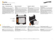
2. Contenuto <strong>del</strong>la fornitura<br />
Il contenuto <strong>del</strong>la fornitura e´come di seguito:<br />
<br />
<br />
<br />
<br />
<br />
<br />
<br />
<strong>Centrale</strong> <strong>radio</strong> <strong>Supercom</strong> <strong>646</strong> con modulo di alimentazione<br />
1 Cassetta in plastica in DIN<br />
4 Viti e 4 piedini per il montaggio a parete<br />
2 sigilli per il coperchio<br />
1 ponte per l´attivazione <strong>del</strong>la batteria<br />
<strong>Manuale</strong><br />
CD con:<br />
Software Tools<strong>646</strong><br />
<strong>Manuale</strong> Tools<strong>646</strong> (PDF)<br />
3. Installazione <strong>del</strong>la centrale <strong>radio</strong><br />
3.1 Montaggio <strong>del</strong>la centrale<br />
3.1.1 Montaggio a parete<br />
La centrale <strong>radio</strong> <strong>Supercom</strong> <strong>646</strong> puo´essere montata in orizzontale oppure alla parete utilizzando<br />
gli accessori forniti con l´apparecchiatura. Il coperchio <strong>del</strong>la parte inferiore e´da rimuovere aprendo<br />
la vite. Rimuovere il coperchio superiore e fissare la parte inferiore dove si trova l´elettronica con le<br />
quattro viti. La centrale puo´essere montata anche su una barra DIN.( vedi pagina 15)<br />
3.2 Alimentazione<br />
3.2.1 Attivazione <strong>del</strong>l´alimentazione<br />
Il cavo di alimentazione oppure la batteria deve essere inserita nella scheda principale.<br />
3.2.2 Attivazione <strong>del</strong>la batteria sulla scheda principale<br />
Durante l´istallazione <strong>del</strong>la centrale devono essere collegate le batterie. Per questo<br />
deve essere inserito il ponte sui due pins sulla prima fila <strong>del</strong>la scheda principale.<br />
Non appena e´inserito il ponte la centrale e´alimentata tramite le batterie ed<br />
i LED in verde ed arancione si accendono contemporaneamente tre volte. Da<br />
questo momento la centrale puo´essere configurata tramite il software di configurazione.<br />
3.2.3 Il modulo batteria per 52 memorizzazioni all´anno<br />
Il modulo batteria e´configurato per massimo 52 memorizzazioni in un anno per una durata di 10<br />
anni per la ricezione di 500 ripartitori oppure 24 memorizzazioni all´anno per 1000 ripartitori.<br />
3.2.4 Modulo alimentazione rete<br />
Inserire il cavo elettrico nella parte inferiore nel foro previsto e collegalo all´alimentatore rete. Il<br />
modulo rete viene collegato tramite un cavo alla scheda principale <strong>del</strong>la centrale. E´necessaria<br />
l´alimentazione rete nel caso di utilizzo di moduli GSM/GPRS. Sulla scheda principale si trova una<br />
batteria backup nel caso di interruzione <strong>del</strong>l´alimentazione.<br />
<strong>Manuale</strong> <strong>Supercom</strong> <strong>646</strong> 12042010<br />
5
3.2.5 GSM/GPRS Modulo<br />
Nel caso la centralina fosse equipaggiata con un modulo GSM/GPRS e´da inserire una scheda<br />
SIM e quindi si deve fare un reset tramite il pulsante sulla scheda principale. Per l´attivazione corretta<br />
<strong>del</strong> modulo GSM/GPRS la centralina deve essere collegata alla corrente.<br />
3.2.6 M-Bus Modulo<br />
Collega il cavo M-Bus e fermalo con un nastro al modulo.<br />
3.3 Chiudere e sigillare l´apparecchio<br />
Dopo l´installazione la centrale <strong>radio</strong> <strong>Supercom</strong> <strong>646</strong> deve essere chiusa. Attenzione ai collegamenti<br />
ed ai cavi. Inserire il coperchio. Avvitare il coperchio. Inserire il sigillo. Aquesto punto la centra<br />
<strong>radio</strong> non puo´essere piu´aperta, se non distruggendo il sigillo. Dopo il sigillo le interfacce USB<br />
e RS 232 non sono piu´accessibili. (vedi pagina 7)<br />
3.4 Parametraggio centrale <strong>radio</strong><br />
La configurazione di parametri <strong>del</strong>la centrale <strong>radio</strong> <strong>Supercom</strong> <strong>646</strong> puo´essere fatta tramite il Software<br />
Tools<strong>646</strong>. La documentazione <strong>del</strong> software viene fornita con il software (Tools<strong>646</strong> <strong>Manuale</strong>).<br />
Il parametraggio puo´essere effettuato tramte l´interfaccia ottica oppure tramite il modulo di comunicazione<br />
che e´nella centrale <strong>radio</strong> (USB, RS-232, M-Bus oder GSM). L´accesso al parametraggio<br />
e´protetto con una password. Con il Software Tools<strong>646</strong> possono essere parametrati o modificati<br />
i seguenti dati:<br />
Numero di identificazione <strong>del</strong>la centrale <strong>radio</strong>.<br />
Ora e data (deve essere inizializzato prima <strong>del</strong>la lettura)<br />
Ora e data <strong>del</strong>la lettura.<br />
Velocita´<strong>del</strong>la trasmissione dati, dipende dal tipo di collegamento (mbus, pc oppure modem)<br />
PIN-Code <strong>del</strong> GSM Modem e numero telefonico per la chiamata, se viene utilizzato<br />
Cambio <strong>del</strong>la password per la protezione di modifica<br />
Cambio <strong>del</strong>la password<br />
Attualizzare il firmware <strong>del</strong>la centrale <strong>radio</strong><br />
3.4.1 Accendere la centrale <strong>radio</strong> tramite il Software Tools<strong>646</strong><br />
Prima di tutto:vedi anche User Guide Tools <strong>646</strong>: allegato il CD con il <strong>Supercom</strong> <strong>646</strong>.<br />
Mettere ora e data <strong>del</strong>la centrale su ora legale.<br />
Creare e memorizzare una lista <strong>del</strong>le apparecchiature <strong>radio</strong> che dovranno essere lette.<br />
Non appena la centrale <strong>radio</strong> e´stata programmata e´da verificare se c´e´comunicazione tra la<br />
supercom <strong>646</strong> e le singole apparecchiature <strong>radio</strong>.<br />
Programmare una lettura immediata come da lista memorizzata.<br />
Assicurarsi che le apparecchiature <strong>radio</strong> siano state lette correttamente. Nel caso affermativo<br />
la central <strong>radio</strong> e disponibile per la configurazione dei dati.<br />
Programmare i dati <strong>del</strong>le apparecchiature <strong>radio</strong>.<br />
<strong>Manuale</strong> <strong>Supercom</strong> <strong>646</strong> 12042010<br />
6
4. Memorizzare i dati ed intervalli <strong>del</strong>le<br />
apparecchiature <strong>radio</strong><br />
Possono essere lette via <strong>radio</strong> solo le apparecchiature Sontex equipaggiate con il modulo <strong>radio</strong>.<br />
Le apparecchiature possono essere lette in 365 giorni <strong>del</strong>l´anno, secondo il piano di lettura, che<br />
viene definito dal tipo di prodotto (ad eccezione <strong>del</strong>le apparecchiature 502/502S/552 e 540 dove<br />
data e ora puo´variare secondo il tipo <strong>del</strong>l´apparecchio). Per la definizione degli intervalli facciamo<br />
riferimento al Menu „data lettura“ <strong>del</strong> software Tools<strong>646</strong>.<br />
Nel caso fosse definita una data specifica, cioe´lettura automatica, in questo caso il supercom <strong>646</strong><br />
inizia a leggere alle ore 18 <strong>del</strong>la data definita.<br />
4.1 Piano Lettura Radio<br />
Durante la lettura l´orario <strong>del</strong>ll´apparecchio <strong>radio</strong> viene sincronizzato con quello <strong>del</strong> supercom <strong>646</strong>.<br />
Per questo e´importante che l´orario <strong>del</strong>la centrale <strong>radio</strong> e´quella <strong>del</strong>l´ora legale.<br />
Product<br />
Final digit<br />
serial number<br />
502 552<br />
502s 552 0<br />
502s 552 1<br />
502s 552 2<br />
502s 552 3<br />
502s 552 4<br />
502s 552 5<br />
502s 552 6<br />
502s 552 7<br />
502s 552 8<br />
502s 552 9<br />
540<br />
556 590 0<br />
556 590 1<br />
556 590 2<br />
556 590 3<br />
556 590 4<br />
556 590 5<br />
556 590 6<br />
556 590 7<br />
556 590 8<br />
556 590 9<br />
539 > SW 1.6<br />
539 ≥ SW 2.3<br />
531<br />
580 581<br />
541<br />
UTC + 1 (Winter Time) by default, but can be changed<br />
0 1 2 3 4 5 6 7 8 9 10 11 12 13 14 15 16 17 18 19 20 21 22 23<br />
Ready, 7 days a week, all year round<br />
Ready, Mo-Fr, 16.6-15.7 by default, but can be changed.<br />
Every 3rd second, Mo-Fr, all year round<br />
Ready, Mo-Fr, all year round<br />
<strong>Manuale</strong> <strong>Supercom</strong> <strong>646</strong> 12042010<br />
7
4.2 Memorizzare i dati<br />
I dati vengono memorizzati nella memoria flash <strong>del</strong> supercom <strong>646</strong>. Questa memoria contiene i<br />
parametri di configurazione <strong>del</strong>la centrale <strong>radio</strong>, la lista <strong>del</strong>le apparecchiature <strong>radio</strong>, la lista <strong>del</strong>le<br />
apparecchiature che dovranno essere lette, i dati <strong>del</strong>l´ultima lettura e l´attualizzazione <strong>del</strong> firmware<br />
<strong>del</strong> supercom <strong>646</strong>. La <strong>Supercom</strong> <strong>646</strong> ha una memoria dove possono essere memorizzate fino a<br />
1000 apparecchiature.<br />
Ripartitore 502/552<br />
Ripartitore 555/556<br />
Contatore <strong>calore</strong> Supercal 539<br />
Unita´di calcolo Supercal 531<br />
Modulo <strong>radio</strong> <strong>Supercom</strong> 581 e <strong>Supercom</strong> 581<br />
Adattatore impulse <strong>radio</strong> Sontex 540<br />
Adattatore impulsi <strong>radio</strong> <strong>Supercom</strong> 541<br />
<strong>Manuale</strong> <strong>Supercom</strong> <strong>646</strong> 12042010<br />
8
5. Descrizione degli LED<br />
La centrale <strong>radio</strong> <strong>Supercom</strong> <strong>646</strong> ha 2 LED:<br />
Un LED verde: indica l´alimentazione e la comunicazione<br />
Un LED arancione: indica errori sui dati <strong>del</strong>le apparecchiature.<br />
L´errore puo´significare che l´orario sulla centrale <strong>radio</strong> non e´valido oppure non inizializzato oppure<br />
che i dati o la memoria difettosa.<br />
verde LED<br />
arancione LED<br />
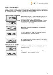
5.1 Indicatore LED<br />
Il posizionamento <strong>del</strong>l´LED indica il modo e lo stato <strong>del</strong>la centrale <strong>radio</strong> <strong>Supercom</strong> <strong>646</strong> come di<br />
seguito:<br />
Stato Alimentazione 230V Alimentazione Batteria<br />
Inizializzazione<br />
LED verde ed arancione: 3 volte accensione di 0,5 Secondi,ogni<br />
secondo.<br />
Modo prova <strong>radio</strong><br />
LED verde:si accende per 0,5 Secondi, ogni Secondo.<br />
LED arancione:si accende discontinuo con il verde.<br />
Normale<br />
LED verde:si accende 40 ms ogni 4<br />
LED verde: ON<br />
Secondi.<br />
LED arancione: OFF<br />
Arancione LED: OFF<br />
Modo riposo<br />
Durante la comunicazione<br />
(ottico 3x)<br />
(interfaccia fissa 2x,<br />
(mobile 1x)<br />
(GSM)<br />
Dopo ogni lettura via<br />
<strong>radio</strong><br />
Orario oppure<br />
memoria non<br />
disponibile<br />
Normale<br />
Orario oppure<br />
memoria non<br />
disponibile<br />
Normale<br />
Lettura corretta<br />
Lettura errata<br />
LED verde: OFF<br />
LED arancione: ON<br />
LED verde: OFF<br />
LED arancione:si accende 40 ms<br />
ogni 8 Secondi.<br />
LED verde:si accende 0,5 Secondi, ogni secondo.<br />
LED arancione: OFF<br />
LED verde: OFF<br />
LED arancione:si accende 0,5 Sekunden,ogni secondo.<br />
LED verde: OFF<br />
LED arancione: OFF<br />
Grüne LED: blinkt während 0,5 Sekunden, einmal für jedes ausgelesene<br />
Gerät.<br />
Orange LED: OFF<br />
LED verde: OFF<br />
LED arancione:si accende 0,5 secondi, una volta per ogni apparecchio<br />
non letto.<br />
OFF = LED spento; ON= LED acceso<br />
<strong>Manuale</strong> <strong>Supercom</strong> <strong>646</strong> 12042010<br />
9
5.2 Problemi con l´alimentazione<br />
Problemi con l´alimentazione (rete oppure batteria) vengono indicati da tutte e due gli LED.<br />
5.2.1 Rete disattivata oppure batteria debole:<br />
Stato<br />
Modo riposo<br />
Normale<br />
Orologio oppure<br />
memoria danneggiata<br />
230V alimentazione disattivata<br />
Batteria debole<br />
LED verde: si accende 40 ms ogni 8 secondi.<br />
LED arancione: OFF<br />
LED verde: OFF<br />
LED arancione:si accende 40 ms ogni 8 secondi.<br />
5.2.2 Batteria per l´alimentazione oppure batteria backup scarica:<br />
Stato Backup Batteria scarica Batteria alimentatione scarica<br />
LED verde:si accendet 2x per 40 ms ogni 8 secondi.<br />
Modo riposo Normale<br />
LED arancione: OFF<br />
Orologio oppure<br />
memoria danneggiata<br />
LED verde: OFF<br />
LED arancione: si accende 2x per 40 ms ogni 8 secondi.<br />
<strong>Manuale</strong> <strong>Supercom</strong> <strong>646</strong> 12042010<br />
10
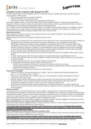
6. Indicazioni generali<br />
Il <strong>Supercom</strong> <strong>646</strong> puo´essere montato solo da personale autorizzato.<br />
Le specifiche tecnico devono essere lette e seguite prima <strong>del</strong>l´installazione.<br />
La qualita´<strong>del</strong>la trasmissione <strong>radio</strong> dipende dal posizionamento <strong>del</strong> supercom<br />
Prima <strong>del</strong>l´installazione <strong>del</strong> supercom <strong>646</strong> il tecnico deve esaminare il corretto posizionamento<br />
<strong>del</strong>l´apparecchio ed accertarsi che tutte le utenze vengono<br />
Il <strong>Supercom</strong> <strong>646</strong> non deve essere montato in ambienti umidi.<br />
Il carico elettrostatico durante il montaggio e´da evitare.Viene consigliato di collegare<br />
l´apparecchio al terra prima di essere toccato.<br />
Attenzione al collegamento <strong>del</strong>l´apparecchio alla rete.<br />
Lunghezza massima <strong>del</strong> cavo RS232 e´di 5 m.<br />
6.1.1 Alimentazione rete disattivato oppure batteria scarica<br />
Nel caso di un malfunzionamento elettrico oppure la batteria scarica l´orologio <strong>del</strong>la central rimane<br />
attivo, mentre il collegamento <strong>del</strong>la <strong>radio</strong> e´attivato. Non e´possibile memorizzare I dati, ma<br />
e´possibile in qualsiasi momento richiedere I dati dal supercom <strong>646</strong> e di leggerli tramite<br />
l´interfaccia ottica oppure tramite altri sistemi senza cavo.<br />
6.1.2 Collegamento elettrico <strong>del</strong> modulo rete<br />
Sono da seguire le normative internazionali e locali. I cavi non devono toccare tubi di una temperatura<br />
oltre i 70 gradi C.<br />
6.1.3 Indicazioni di sicurezza<br />
La centrale <strong>radio</strong> <strong>Supercom</strong> <strong>646</strong> ha lasciato la fabbrica in perfetto stato, anche dal punto di vista di<br />
sicurezza <strong>del</strong>l´apparecchio.<br />
Per mantenre questo stato l´utente deve leggere attentamente questo manuale La temperature<br />
massima di lavoro e´di 55 gradi C. Qualora la temperatura fosse superiore, la durata <strong>del</strong>la batteria<br />
potrebbe essere ridotta.<br />
6.2 Sigillo di sicurezza<br />
L´apparecchio e´protetto da un sigillo. Cosi puo´essere garantito che la centrale non viene aperta.<br />
Il sigillo puo´essere rotto o rimosso solo da personale autorizzato. Nel caso di disattenzione decade<br />
la garanzie sul prodotto.<br />
.<br />
Sigillo da inserire<br />
<strong>Manuale</strong> <strong>Supercom</strong> <strong>646</strong> 12042010<br />
11
6.3 Dati tecnici<br />
Generale<br />
Temperatura di lavoro 5° fino 55°C<br />
Temperatura magazzino -10 fino 60°C (ambiente asciu tto)<br />
Peso<br />
0,340 kg<br />
(Rete 230V + GSM + RS232)<br />
Cassetta<br />
Classe di protezione IP 40 (secondo DIN 40050)<br />
(con eccezione <strong>del</strong> passaggio <strong>del</strong> cavo nella<br />
parte inferiore)<br />
Dimensioni<br />
Cassetta 180x154x46 mm<br />
Interfaccia comunicazione<br />
L´interfaccia ottica sul supercom <strong>646</strong> e´standard.<br />
USB<br />
RS-232<br />
M-Bus<br />
GSM/GPRS<br />
Comunicazione <strong>radio</strong><br />
Comucazione Bidirezionale<br />
Modulazione FSK<br />
Frequenza 433.82 MHz<br />
Protocollo <strong>radio</strong> Radian 0<br />
Trasmissione dati EN 60870-5 (M-Bus)$<br />
PER 10 mW<br />
Distanza all´aperto ca. 300 m<br />
Distanza nell´interno stabile ca. 30 m*<br />
* valore dipende dal tipo di costruzione <strong>del</strong>lo stabile.<br />
Dati elettronici<br />
<br />
Modulo rete Backup Batteria:<br />
3V Lithium Mangan Dioxid (Li-MnO2) Formato 2 / 3 A<br />
Modulo rete Batteria :<br />
3,6V Lithium Thionyl Chlorid (Li-SOCI2) Formato D + 2 x 3V Formato A<br />
(saldata sulla scheda principale).<br />
<strong>Manuale</strong> <strong>Supercom</strong> <strong>646</strong> 12042010<br />
12
6.4 Dimensioni<br />
Interno<br />
<strong>Supercom</strong> <strong>646</strong> Batteria, USB<br />
<strong>Supercom</strong> <strong>646</strong>, Netz 230 VAC, USB, GSM<br />
Visura parziale sotto con predisposizione<br />
montaggio su barra DIN<br />
<strong>Manuale</strong> <strong>Supercom</strong> <strong>646</strong> 12042010<br />
13
7. M-Bus Protocollo di comunicazione<br />
7.1 Introduzione<br />
La centrale <strong>radio</strong> <strong>Supercom</strong> <strong>646</strong> possiede il protocollo di comunicazione M-Bus Protokoll secondo<br />
la normativa europea EN1434.<br />
Il protocollo M-Bus appoggia l´indirizzo secondario. Per ulterior informazioni sull´M-Bus collegarsi<br />
alla pagina: http://www.m-bus.com/<br />
7.2 Divisione <strong>del</strong>la memoria <strong>del</strong>la centrale<br />
La memoria <strong>del</strong>la centrale puo´essere divisa in tre settori.Ognuno dei tre settori secondo il protocollo<br />
MBus puo´essere indirizzato come letto e scritto oppure solo letto..<br />
1. Dati configurazione <strong>del</strong>la centrale (leggere e scrivere)<br />
2. Dati con la lista <strong>del</strong>le apparecchiature memorizzate (leggere e scrivere)<br />
3. Dati con i consumi. Dati letti dalla centrale <strong>radio</strong> (letti)<br />
7.3 Principio di lettura<br />
La centrale <strong>radio</strong> contiene 2 apparecchi distinti:<br />
1. La centrale.<br />
2. L´apparecchio di lettura dove i dati di lettura vengono memorizzati nella memoria <strong>del</strong>la centrale.<br />
La central <strong>radio</strong> <strong>Supercom</strong> <strong>646</strong> invia diversi blocchi. I primi due blocchi sono destinati alla centrale.<br />
I seguenti blocchi dipendono dalle quantita´<strong>del</strong>le apparecchiature <strong>radio</strong>, che sono inserite nella<br />
lista <strong>radio</strong>:<br />
1. Frames Nr.1 e Nr. 2 per la centrale<br />
2. Frames Nr. 3…Nr. xx contenuti nella lista <strong>del</strong>le apparecchiature <strong>radio</strong> che dovranno essere<br />
letti dalla centrale. Ognuno dei Frame contiene quattro apparecchiature.<br />
<strong>Manuale</strong> <strong>Supercom</strong> <strong>646</strong> 12042010<br />
14
7.3.1 Descrizione per la lettura <strong>del</strong>la configurazione e la lista apparecchiature<br />
<strong>del</strong>la centrale <strong>radio</strong><br />
Vedi allegato A, Pagina 24, per descrizione dettagliata.<br />
1. Frame Richiesta “Rsp_1” con “REQ_UD2” (Ind.253).<br />
Frame “Rsp_1” (contiene informazioni errate <strong>del</strong>la centrale)<br />
End<br />
User Data<br />
Start<br />
Field Frame bytes in hex (Note 1) Coding Comment<br />
Start, Length<br />
68,Le Le,68<br />
Control 08 Respond with user data, RSP_UD<br />
Address<br />
FD<br />
Control Information 72 Variable structure respond<br />
XML attributes<br />
Name<br />
SubUnit<br />
Tariff<br />
Storage<br />
Function‡<br />
Identification number xx xx xx xx A, 32 bits IdentificationNumber<br />
Manufacturer ID EE 4D C, 16 bits "SON" Manufacturer<br />
Version of meter 0A C, 8 bits 10 Version<br />
Device type 0E D, 8 bits Bus / System component DeviceType<br />
Access number xx C, 8 bits AccessNumber<br />
Status st Ds, 8 bits Status<br />
Signature 00 00 C, 16 bits Not used Signature<br />
Detailed errors 02,FD 17,er er D, 16 bits ErrorFlags 0 0 0 0<br />
More records in next telegram mo Start of manufacturer specific data ManufacturerDataBlock<br />
Check Sum<br />
cs<br />
Stop 16<br />
<br />
Parent tag<br />
Symbols<br />
‡ Function: 0=instantaneous, 1=maximum, 2=minimum, 3=during error state<br />
Notes<br />
1. For non hexadecimal or lower case digits see the detailled description in the Keys sheet.<br />
<strong>Manuale</strong> <strong>Supercom</strong> <strong>646</strong> 12042010<br />
15
2. Frame Richiesta “Rsp_2” con “REQ_UD2” (Ind.253).<br />
Frame “Rsp_2” (contiene informazioni per la configurazione <strong>del</strong>la central <strong>radio</strong>)<br />
XML attributes<br />
Start<br />
User Data<br />
Field Frame bytes in hex (Note 1) Coding Comment<br />
Start, Length<br />
68,Le Le,68<br />
Control 08 Respond with user data, RSP_UD<br />
Address<br />
FD<br />
Control Information 72 Variable structure respond<br />
Identification number xx xx xx xx A, 32 bits IdentificationNumber<br />
Manufacturer ID EE 4D C, 16 bits "SON" Manufacturer<br />
Version of meter 0A C, 8 bits 10 Version<br />
Device type 0E D, 8 bits Bus / System component DeviceType<br />
Access number xx C, 8 bits AccessNumber<br />
Status st Ds, 8 bits Status<br />
Signature 00 00 C, 16 bits Not used Signature<br />
Detailed errors 02,FD 17,er er D, 16 bits ErrorFlags 0 0 0 0<br />
Current date & time 04,6D,xx xx xx xx F, 32 bits DateAndTime 0 0 0 0<br />
Day of week 01,FD 63,xx C, 8 bits 1: Monday, 7: Sunday DayOfWeek 0 0 0 0<br />
Reading date 1 44,6D,xx xx xx xx F, 32 bits DateAndTime 0 0 1 0<br />
Reading period 1 41,FD si,xx C, 8 bits day | month StorageInterval 0 0 1 0<br />
Reading date 2 84 01,6D,xx xx xx xx F, 32 bits DateAndTime 0 0 2 0<br />
Reading period 2 81 01,FD si,xx C, 8 bits day | month StorageInterval 0 0 2 0<br />
Reading date 3 C4 01,6D,xx xx xx xx F, 32 bits DateAndTime 0 0 3 0<br />
Reading period 3 C1 01,FD si,xx C, 8 bits day | month StorageInterval 0 0 3 0<br />
Reading date 4 84 02,6D,xx xx xx xx F, 32 bits DateAndTime 0 0 4 0<br />
Reading period 4 81 02,FD si,xx C, 8 bits day | month StorageInterval 0 0 4 0<br />
Date of last reading C2 0F,6C,xx xx G, 16 bits Date 0 0 31 0<br />
Optical baudrate 02,FD 1C,xx xx C, 16 bits bit/s BaudRate 0 0 0 0<br />
Optical byte format 01,FF 0F,bf C, 8 bits § ByteFormat 0 0 0 0<br />
Optical general timeout 02,FF 12,xx xx C, 16 bits § 1/2 s Timeout 0 0 0 0<br />
Optical inactivity timeout 82 10,FF 12,xx xx C, 16 bits § 1/2 s Timeout 0 1 0 0<br />
Optical byte interval 82 20,FF 10,xx xx C, 16 bits § 1/32768 s Timeout 0 2 0 0<br />
K1 module type 81 40,FF 1D,mt C, 8 bits § InterfaceType 1 0 0 0<br />
K1 module baudrate 82 40,FD 1C,xx xx C, 16 bits bit/s BaudRate 1 0 0 0<br />
K1 module byte format 81 40,FF 0F,bf C, 8 bits § ByteFormat 1 0 0 0<br />
K1 module general timeout 82 40,FF 12,xx xx C, 16 bits § 1/2 s Timeout 1 0 0 0<br />
K1 module inactivity timeout 82 50,FF 12,xx xx C, 16 bits § 1/2 s Timeout 1 1 0 0<br />
K1 module byte interval 82 60,FF 10,xx xx C, 16 bits § 1/32768 s Timeout 1 2 0 0<br />
K2 module type 81 80 40,FF 1D,mt C, 8 bits § InterfaceType 2 0 0 0<br />
K2 module baudrate 82 80 40,FD 1C,xx xx C, 16 bits bit/s BaudRate 2 0 0 0<br />
K2 module byte format 81 80 40,FF 0F,bf C, 8 bits § ByteFormat 2 0 0 0<br />
K2 module general timeout 82 80 40,FF 12,xx xx C, 16 bits § 1/2 s Timeout 2 0 0 0<br />
K2 module inactivity timeout 82 90 40,FF 12,xx xx C, 16 bits § 1/2 s Timeout 2 1 0 0<br />
K2 module byte interval 82 A0 40,FF 10,xx xx C, 16 bits § 1/32768 s Timeout 2 2 0 0<br />
K2 module GSM PIN code 8D 80 40,FF 18,Lp ch ch ch LVAR § empty = disabled PinCode 2 0 0 0<br />
ch ch ch ch ch<br />
K2 module call back number<br />
8D 80 40,FF 1E,Ln ch ch ch LVAR § empty = disabled PhoneNumber 2 0 0 0<br />
ch ch ch ch ch ch ch ch ch<br />
ch ch ch ch<br />
Name<br />
SubUnit<br />
Tariff<br />
Storage<br />
Function‡<br />
Parent tag<br />
<br />
<br />
End<br />
Parameter flags 01,FD 66,pp D, 8 bits StateOfParameterActivation 0 0 0 0<br />
Device write protect 01,FF 04,wp D, 8 bits § DeviceWriteProtect 0 0 0 0<br />
Internal version 0C,FD 0F,xx xx xx xx A, 32 bits OtherSoftwareVersion 0 0 0 0<br />
Hardware version 02,FD 0D,xx xx C, 16 bits HardwareVersion 0 0 0 0<br />
Fabrication Number 0C,78,xx xx xx xx A, 32 bits FabricationNumber 0 0 0 0<br />
More records in next telegram mo Start of manufacturer specific data ManufacturerDataBlock<br />
Check Sum<br />
cs<br />
Stop 16<br />
<strong>Manuale</strong> <strong>Supercom</strong> <strong>646</strong> 12042010<br />
16
Keys<br />
Optional record<br />
xx<br />
yy<br />
bf<br />
ch<br />
cs<br />
Value LSByte first<br />
Value MSByte first<br />
Byte format<br />
bit1..0 Data bit 10b: 7 bits data; 11b: 8 bits data<br />
bit3..2 Stop bit 00b: 1 bit stop; 10b: 2 bits stop<br />
bit6..4 Parity 000b: none; 001b: odd; 010b: even<br />
bit7 Reserved always 0<br />
ASCII character<br />
The value of Check Sum is calculated from arithmetical sum modulo 256 of<br />
er er Detailed errors <strong>646</strong> M-Bus standard<br />
bit0 † Tamper<br />
bit1 † Battery low<br />
bit2 † External alarm<br />
bit3 † Battery cut<br />
bit7..4 † RSSI<br />
0000b † RSSI not available<br />
0001b † -100 dBm or less<br />
0010b † -90 dBm<br />
0011b † -80 dBm<br />
0100b † -70 dBm<br />
0101b † -60 dBm<br />
0110b † -50 dBm<br />
0111b † -40 dBm<br />
1000b † -30 dBm<br />
1001b † -20 dBm<br />
1010b † -10 dBm<br />
1011b † 0 dBm<br />
1100b † +10 dBm<br />
1101b † +20 dBm or more<br />
1110b † Reserved<br />
1111b † Reserved<br />
bit8 SND_UD frame: unknown CI.<br />
bit9 SND_UD frame, structured write: unknown field.<br />
bit10 Access right violation.<br />
bit11 SND_UD frame, structured write: bad field size.<br />
bit12 Memory overflow.<br />
bit13 †<br />
bit14 Invalid time clock<br />
bit15 †<br />
Le<br />
Length of the M-Bus frame. The fields Start, Length, Check Sum and Stop (6<br />
bytes) are not included in the calculation of the Length field. The Length field is<br />
repeated twice preceded and followed by the Start field 68h.<br />
<strong>Manuale</strong> <strong>Supercom</strong> <strong>646</strong> 12042010<br />
17
Ld<br />
Ln<br />
Lp<br />
Length of the special record "Device entry"<br />
18..46<br />
The first byte following the length is the LSB of the "Identification Number".<br />
Length of ASCII character string representing the call back phone number<br />
0 The call back function is disabled<br />
1..16 Length of the phone number. The call back function is enabled.<br />
Warning: according to the M-Bus standard, the first byte following the length byte is<br />
the rightmost character of the string, and the last byte is the leftmost character.<br />
Length of ASCII character string representing the GSM PIN code<br />
0 No PIN code<br />
1..8 Length of the PIN code<br />
Warning: according to the M-Bus standard, the first byte following the length byte is<br />
the rightmost character of the string, and the last byte is the leftmost character.<br />
mo More records in next telegram :<br />
0Fh no<br />
1Fh yes<br />
mt<br />
pp<br />
Module type<br />
2 USB (slave)<br />
4 M-Bus (slave)<br />
8 GSM<br />
12 RS-232 DCE<br />
255 No module plugged<br />
Parameter flags<br />
Warning: don't change the unused or reserved bits.<br />
bit0 When the selected device is in the device list, but not yet read :<br />
0: send an "empty" RSP_UD (with just the 12 bytes header)<br />
1: do not send anything<br />
others Reserved, do not change this bits<br />
si Storage interval<br />
27h day<br />
When the value of the storage interval is 0 [day], the reading is done only once,<br />
as soon as possible according to the reading periods of the devices.<br />
28h month<br />
When the value of the storage interval is 0 [month], the reading is done only<br />
st Status <strong>646</strong> M-Bus standard<br />
bit1..0 Application Application<br />
00b No error No error<br />
01b † Application busy<br />
10b Any application error Any application error<br />
11b † Reserved<br />
bit2 Main power cut Power low<br />
or battery low<br />
bit3 † Permanent error<br />
bit4 † Temporary error<br />
bit5 † Manufacturer specific<br />
bit6 Invalid time clock Manufacturer specific<br />
bit7 † Manufacturer specific<br />
wp<br />
Device write protect<br />
00 write protect disable<br />
01 write protect enable<br />
† Not used.<br />
<strong>Manuale</strong> <strong>Supercom</strong> <strong>646</strong> 12042010<br />
18
Start<br />
3. Per la lettura di un apparecchio che e´contenuto nella lista <strong>del</strong>la centrale <strong>radio</strong> e´da inviare un<br />
comando “REQ_UD2" (Ind.253) :<br />
Frame “Rsp_3” oppure “Rsp_xx” secondo le quantita´<strong>del</strong>le apparecchiature <strong>radio</strong> memorizzate<br />
nella centrale <strong>radio</strong>.<br />
Field Frame bytes in hex (Note 1) Coding Comment<br />
Start, Length<br />
68,Le Le,68<br />
Control 08 Respond with user data, RSP_UD<br />
Address<br />
FD<br />
Control Information 72 Variable structure respond<br />
Identification number xx xx xx xx A, 32 bits IdentificationNumber<br />
Manufacturer ID EE 4D C, 16 bits "SON" Manufacturer<br />
Version of meter 0A C, 8 bits 10 Version<br />
Device type 0E D, 8 bits Bus / System component DeviceType<br />
Access number xx C, 8 bits AccessNumber<br />
Status st Ds, 8 bits Status<br />
XML attributes<br />
Signature 00 00 C, 16 bits Not used Signature<br />
Entry of device list 0D,FF 16,Ld xx xx xx xx xx LVAR § See "Device Entry" sheet 0 0 0 0<br />
xx xx xx xx xx xx xx xx xx<br />
xx xx xx xx xx xx xx xx xx<br />
xx xx xx xx xx xx xx xx xx<br />
xx xx xx xx xx xx xx xx xx<br />
xx xx xx xx xx<br />
Name<br />
SubUnit<br />
Tariff<br />
Storage<br />
Function‡<br />
User Data<br />
Entry of device list<br />
Entry of device list<br />
Entry of device list<br />
0D,FF 16,Ld xx xx xx xx xx<br />
xx xx xx xx xx xx xx xx xx<br />
xx xx xx xx xx xx xx xx xx<br />
xx xx xx xx xx xx xx xx xx<br />
xx xx xx xx xx xx xx xx xx<br />
xx xx xx xx xx<br />
0D,FF 16,Ld xx xx xx xx xx<br />
xx xx xx xx xx xx xx xx xx<br />
xx xx xx xx xx xx xx xx xx<br />
xx xx xx xx xx xx xx xx xx<br />
xx xx xx xx xx xx xx xx xx<br />
xx xx xx xx xx<br />
0D,FF 16,Ld xx xx xx xx xx<br />
xx xx xx xx xx xx xx xx xx<br />
xx xx xx xx xx xx xx xx xx<br />
xx xx xx xx xx xx xx xx xx<br />
xx xx xx xx xx xx xx xx xx<br />
xx xx xx xx xx<br />
LVAR § See "Device Entry" sheet 0 0 0 0<br />
LVAR § See "Device Entry" sheet 0 0 0 0<br />
LVAR § See "Device Entry" sheet 0 0 0 0<br />
End<br />
More records in next mo Start of manufacturer specific data ManufacturerDataBlock<br />
telegram<br />
Check Sum<br />
cs<br />
Stop 16<br />
<strong>Manuale</strong> <strong>Supercom</strong> <strong>646</strong> 12042010<br />
19
7.3.2 Richiedere i dati letti e memorizzati <strong>del</strong>le apparecchiature <strong>radio</strong><br />
Dopo che la centrale <strong>radio</strong> ha letto le apparecchiature che sono sulla lista, i dati vengono memorizzati<br />
sulla memoria <strong>del</strong>la centrale.<br />
Per leggere I dati bisogna procedere in questo modo:<br />
Vedasi allegato A, « Leggere i dati memorizzati nella centrale <strong>radio</strong> », per una procedura di lettura<br />
dettagliata.<br />
Il campo “Device Entry” (Registrazione apparecchiatura) contiene informazioni <strong>del</strong>le apparecchiature<br />
che devono essere lette:<br />
Device type<br />
Values to read<br />
Identification<br />
Number<br />
Manufacturer<br />
ID<br />
Version<br />
(Generation)<br />
Device Type<br />
( Medium)<br />
Radio<br />
Address<br />
Radio Device<br />
Type<br />
Options<br />
Maximal<br />
Frame<br />
Application<br />
Reset<br />
Date of Last<br />
Type A C C D A C D C D G A<br />
Bytes 4 2 1 1 4 1 1 1 1 2 n*4<br />
Notes a, e a, e a a b, e b b b b c, e b, d, e<br />
HCA 502S, 552 All values (compact reading) xxxxxxxxh 4DEEh 4 08h xxxxxxxxh 0 80h 01h 01h 0101h xxxxxxxxh<br />
Current values<br />
80h 01h 00h<br />
Supercal 539 PLUS<br />
+ monthly energy 80h 02h 00h<br />
xxxxxxxxh 4DEEh 4 04h xxxxxxxxh 1<br />
+ monthly volume 80h 03h 00h<br />
0101h xxxxxxxxh<br />
All values<br />
80h 05h 00h<br />
540 pulses All values xxxxxxxxh 4DEEh 1 00h xxxxxxxxh 2 80h 04h 00h 0101h xxxxxxxxh<br />
531 frames 106, 107 xxxxxxxxh 4DEEh 0 04h xxxxxxxxh 3 80h 04h 02h 0101h xxxxxxxxh<br />
590 WCA All values xxxxxxxxh 38AFh 4 07h xxxxxxxxh 81h 01h 00h 0101h xxxxxxxxh<br />
580 Water counter All values xxxxxxxxh 4DEEh 10 07h xxxxxxxxh 4 80h 01h 00h 0101h xxxxxxxxh<br />
581 Water counter All values xxxxxxxxh 4DEEh 20 07h xxxxxxxxh 80h 01h 00h 0101h xxxxxxxxh<br />
556 HCA<br />
Current values<br />
A1h 01h 00h<br />
xxxxxxxxh 4DEEh 16 08h xxxxxxxxh 5<br />
All values<br />
A1h 02h 00h<br />
0101h xxxxxxxxh<br />
Successful<br />
Reading<br />
Radio<br />
Repeater<br />
Address<br />
Notes<br />
a This value is part of the M-Bus secondary address used to access the data of a device stored in <strong>646</strong>.<br />
It is updated by <strong>646</strong> according to the value really read from the device by <strong>radio</strong>.<br />
b This value is used to access the device by <strong>radio</strong>. It is never modified by the <strong>646</strong> itself.<br />
c The date 1.1.2000 means "not yet successful read", coded in M-Bus G type: 0101h<br />
d The number of "Radio Repeater Address" specified must be in the range 0 to 7.<br />
e Multibytes values are transmitted with LSB first.<br />
Compilare il « Scelta dei Slaves » SND_UD (Master a Slave)<br />
XML attributes<br />
Start<br />
User Data<br />
End<br />
Field Frame bytes in hex (Note 1) Coding Comment<br />
Start, Length 68,Le Le,68<br />
Control 73|53 Send user data to slave, SND_UD<br />
Address<br />
FD<br />
Control Information 52 Selection of slaves<br />
Identification number xx xx xx xx A, 32 bits IdentificationNumber<br />
Manufacturer ID xx xx C, 16 bits Manufacturer<br />
Version of meter xx C, 8 bits Version<br />
Device type xx D, 8 bits DeviceType<br />
Check Sum cs<br />
Stop 16<br />
Name<br />
SubUnit<br />
Tariff<br />
Storage<br />
Function‡<br />
Parent tag<br />
<strong>Manuale</strong> <strong>Supercom</strong> <strong>646</strong> 12042010<br />
20
I valori che si trovano nel «Numero di identificazione, Produttore ID, Versione e tipo apparecchiatura<br />
» die blocchi Rsp_xx (Tipo apparecchiatura) befinden, devono essere trasferiti nel campo blocchi<br />
« Scelta dei »<br />
7.4 Principio di scrittura <strong>del</strong>la centrale <strong>radio</strong><br />
Vedasi allegato B per una descrizione dettagliata <strong>del</strong> principio di scrittura.<br />
Vedasi capitol password per definieren il campo „Password“ nel blocco.<br />
7.4.1 Cambio <strong>del</strong>la configurazione nella central <strong>radio</strong><br />
Riempire il Frame « Structured write » SND_UD (Master an Slave)<br />
XML attributes<br />
Start<br />
Field Frame bytes in hex (Note 1) Coding Comment<br />
Start, Length<br />
68,Le Le,68<br />
Control 73|53 Send user data to slave, SND_UD<br />
Address<br />
FD<br />
Control Information 51 Stuctured write telegram<br />
Enter password 0C,FD 16,xx xx xx xx A, 32 bits 0 0 0 0<br />
Set new password 4C,FD 16,xx xx xx xx A, 32 bits Note 2 0 0 1 0<br />
Current date & time 04,6D,xx xx xx xx F, 32 bits Notes 2 and 3 DateAndTime 0 0 0 0<br />
Identification number 0C,79,xx xx xx xx A, 32 bits Note 2 IdentificationNumber 0 0 0 0<br />
K2 module GSM PIN code 82 80 40,FF 18,xx xx A, 16 bits § empty = disabled, Notes 2 and 7 PinCode 2 0 0 0<br />
K2 module call back number 8D 80 40,FF 1E,Ln ch ch ch LVAR § empty = disabled, Note 2 PhoneNumber 2 0 0 0<br />
ch ch ch ch ch ch ch ch ch<br />
ch ch ch ch<br />
Name<br />
SubUnit<br />
Tariff<br />
Storage<br />
Function‡<br />
Parent tag<br />
User Data<br />
Add entry to device list<br />
0D,FF 16,Ld xx xx xx xx xx LVAR § Notes 2, 4 and 6 0 0 0 0<br />
xx xx xx xx xx xx xx xx xx<br />
xx xx xx xx xx xx xx xx xx<br />
xx xx xx xx xx xx xx xx xx<br />
xx xx xx xx xx xx xx xx xx<br />
xx xx xx xx xx<br />
Clear device list<br />
0D,FF 17,08 FF FF FF<br />
FF FF FF FF FF<br />
LVAR Notes 2 and 5 0 0 0 0<br />
Parameter flags (Bits set) 01,FD E6 03,pp D, 8 bits Mentioned bits are setted. Note 8 StateOfParameterActivation 0 0 0 0<br />
Parameter flags (Bits clear) 01,FD E6 06,pp D, 8 bits Mentioned bits are cleared. Note 9 StateOfParameterActivation 0 0 0 0<br />
End<br />
Check Sum<br />
cs<br />
Stop 16<br />
Symbols<br />
‡ Function: 0=instantaneous, 1=maximum, 2=minimum, 3=during error state<br />
§ manufacturer specific VIFE<br />
Notes<br />
1. For non hexadecimal or lower case digits see the detailled description in the Keys sheet.<br />
2. The password must be entered before to change this value<br />
3. Use the standard time all the year regardless of the daylight-saving time (as the <strong>radio</strong> devices).<br />
4. The <strong>646</strong> needs at least 50 ms per device to add them to the list, don't send frame during this period.<br />
5. The <strong>646</strong> needs at least 7.5 s to do this operation, don't send frame during this period.<br />
6. At the end of the current link, the <strong>646</strong> needs up to 3 minutes to update its internal data and it is unavailable.<br />
7. At the end of the current link, the <strong>646</strong> needs about 6 s to reinitialize the modem and it is unavailable.<br />
8. For example, to set the bit0 the value is 01h, to set both bit1 and bit3 the value is 0Ah.<br />
9. For example, to clear the bit0 the value is 01h, to clear both bit1 and bit3 the value is 0Ah.<br />
Tutti i campi <strong>del</strong> Frames Rsp_2,che contengono informazioni sulla configurazione <strong>del</strong>la centrale<br />
<strong>radio</strong>, possono essere modificati ed inseriti nel blocco « Structure write ».<br />
<strong>Manuale</strong> <strong>Supercom</strong> <strong>646</strong> 12042010<br />
21
7.4.1 Password <strong>del</strong>la centrale <strong>radio</strong><br />
Per modificare la configurazione <strong>del</strong>la centrale <strong>radio</strong> e´importante compilare il campo « Passwort »<br />
<strong>del</strong> Frames « Structured write » SND_UD (Master a Slave).<br />
La « Passwort » deve essere sempre al primo posto <strong>del</strong> blocco, altrimenti non e´possibile<br />
modificare la configurazione <strong>del</strong>la centrale <strong>radio</strong>.<br />
La central <strong>radio</strong> viene fornita con la seguente password: 00001234<br />
La password puo´essere modificata a suo piacimento.<br />
7.4.2 Aggiungere un´apparecchiatura nella lista <strong>del</strong>la centrale<br />
Compilare nel Frame « Structured write » SND_UD con le informazioni <strong>del</strong>l´apparecchiatura che<br />
deve essere inserita nella lista.<br />
Vedi campo « Device Entry » (Registrazione apparecchio) per informazioni che dovranno essere<br />
aggiunte secondo il tipo di apparecchiatura.<br />
Osseravazioni: La passowrd deve essere sempre presente nel blocco. E sempre al primo posto<br />
<strong>del</strong> blocco.<br />
7.4.3 Cambio <strong>del</strong>la lista apparecchiature<br />
Per modificare la lista <strong>del</strong>le apparecchiature procedere come di seguito:<br />
1. Chiamare la liste esistente nella central e copiarla in un software esterno. Cambiare la lista<br />
<strong>del</strong>le apparecchiature.<br />
2. Cancellare la lista nella centrale <strong>radio</strong>.<br />
3. Inserire la lista modificata nella centrale.<br />
Questa procedura puo´essere effettuata con il software allegato alla centrale <strong>radio</strong> Tools<strong>646</strong> oppure<br />
tramite un software esterno con i comandi M-Bus.<br />
<strong>Manuale</strong> <strong>Supercom</strong> <strong>646</strong> 12042010<br />
22
8. Utilizzo<br />
8.1 Attualizzare il Firmware<br />
La Firmware <strong>del</strong>la centrale <strong>radio</strong> <strong>Supercom</strong> <strong>646</strong> puo´essere attualizzata con un computer tramite<br />
l´interfaccia di comunicazione <strong>del</strong>la centrale con il Software Tools<strong>646</strong>.<br />
<strong>Manuale</strong> <strong>Supercom</strong> <strong>646</strong> 12042010<br />
23
9. Allegato A<br />
9.1 Lettura <strong>del</strong>la configurazione <strong>del</strong>la centrale <strong>radio</strong><br />
<strong>Manuale</strong> <strong>Supercom</strong> <strong>646</strong> 12042010<br />
24
9.2 Lesen der in der Funkzentrale gespeicherten<br />
Geräteliste<br />
Repeat to read all<br />
frames of device list<br />
<strong>Manuale</strong> <strong>Supercom</strong> <strong>646</strong> 12042010<br />
25
9.3 Leggere i dati <strong>del</strong>le apparecchiature lette e<br />
memorizzate nella centrale <strong>radio</strong><br />
Il Frame RSP_UP contiene di dati letti <strong>del</strong>l´apparecchiatura scelta. Questo Frame RSP_UD<br />
e´specifico per ogni apparecchiatura <strong>radio</strong> Sontex. Per la descrizione dei M-Bus Frames rivolgersi<br />
alla Sontex oppure il distributore di zona.<br />
<strong>Manuale</strong> <strong>Supercom</strong> <strong>646</strong> 12042010<br />
26
10. Allegato B<br />
10.1 Processo di configurazione e scrittura <strong>del</strong>la<br />
centrale <strong>radio</strong><br />
PC <strong>646</strong><br />
Send_NKE (Adr. 253)<br />
SND_UD (C=73h | 53h, Adr. 253 with :<br />
identification number, manufacturer id,...)<br />
Ack<br />
SND_UD (C=73h, Adr. 253 with any combination of<br />
parameters supported by device)<br />
Ack<br />
Req_UD2 (C=7Bh, Adr. 253)<br />
Check for M-Bus<br />
application error in<br />
Status field.<br />
RSP_UD<br />
<strong>Manuale</strong> <strong>Supercom</strong> <strong>646</strong> 12042010<br />
27
CD<br />
<strong>Manuale</strong> <strong>Supercom</strong> <strong>646</strong> 12042010<br />
28
La presente versione in italiano e´una versione abbreviata. La versione completa e´disponibile in<br />
lingua inglese, francese o tedesco presso il sito www.sontex.ch<br />
Conformita´secondo R&TTE 1999/5/CE<br />
La dichiarazione di conformita´e´sul Homepage:<br />
www.sontex.ch<br />
Supporto tecnico<br />
Per il supporto tecnico rivolgersi al distributore locale <strong>del</strong>la Sontex oppure direttamente alla Sontex<br />
SA.<br />
Hotline Sontex:<br />
sontex@sontex.ch<br />
+41 32 488 30 04<br />
Distributore per l´Italia: Enercom srl mail:assistenza@enercomit.com<br />
Via G. Ferraris 5b, 42100 Reggio Emilia (RE)<br />
Tel. +390522554012 Fax +390522331705<br />
© Sontex SA 2009 0<strong>646</strong>P200<br />
<strong>Manuale</strong> <strong>Supercom</strong> <strong>646</strong> 12042010<br />
29