Manual de instalación y mantenimiento - Astral Pool
Manual de instalación y mantenimiento - Astral Pool
Manual de instalación y mantenimiento - Astral Pool

Create successful ePaper yourself
Turn your PDF publications into a flip-book with our unique Google optimized e-Paper software.
ENGLISH<br />
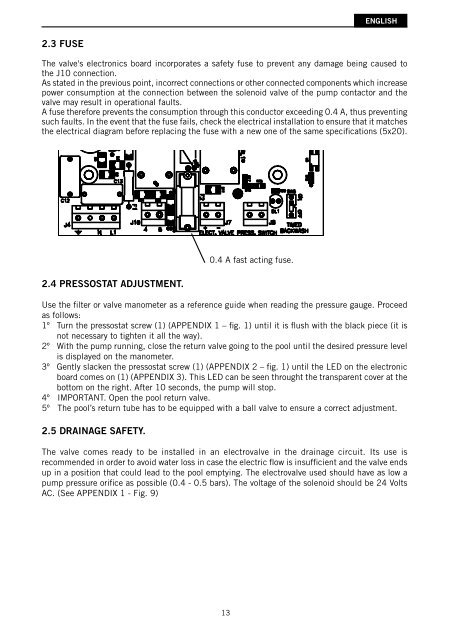
2.3 FUSE<br />
The valve's electronics board incorporates a safety fuse to prevent any damage being caused to<br />
the J10 connection.<br />
As stated in the previous point, incorrect connections or other connected components which increase<br />
power consumption at the connection between the solenoid valve of the pump contactor and the<br />
valve may result in operational faults.<br />
A fuse therefore prevents the consumption through this conductor exceeding 0.4 A, thus preventing<br />
such faults. In the event that the fuse fails, check the electrical installation to ensure that it matches<br />
the electrical diagram before replacing the fuse with a new one of the same specifi cations (5x20).<br />
2.4 PRESSOSTAT ADJUSTMENT.<br />
0.4 A fast acting fuse.<br />
Use the fi lter or valve manometer as a reference gui<strong>de</strong> when reading the pressure gauge. Proceed<br />
as follows:<br />
1º Turn the pressostat screw (1) (APPENDIX 1 – fi g. 1) until it is fl ush with the black piece (it is<br />
not necessary to tighten it all the way).<br />
2º With the pump running, close the return valve going to the pool until the <strong>de</strong>sired pressure level<br />
is displayed on the manometer.<br />
3º Gently slacken the pressostat screw (1) (APPENDIX 2 – fi g. 1) until the LED on the electronic<br />
board comes on (1) (APPENDIX 3). This LED can be seen throught the transparent cover at the<br />
bottom on the right. After 10 seconds, the pump will stop.<br />
4º IMPORTANT. Open the pool return valve.<br />
5º The pool’s return tube has to be equipped with a ball valve to ensure a correct adjustment.<br />
2.5 DRAINAGE SAFETY.<br />
The valve comes ready to be installed in an electrovalve in the drainage circuit. Its use is<br />
recommen<strong>de</strong>d in or<strong>de</strong>r to avoid water loss in case the electric fl ow is insuffi cient and the valve ends<br />
up in a position that could lead to the pool emptying. The electrovalve used should have as low a<br />
pump pressure orifi ce as possible (0.4 - 0.5 bars). The voltage of the solenoid should be 24 Volts<br />
AC. (See APPENDIX 1 - Fig. 9)<br />
13