Manual de instalación y mantenimiento - Astral Pool
Manual de instalación y mantenimiento - Astral Pool
Manual de instalación y mantenimiento - Astral Pool

Create successful ePaper yourself
Turn your PDF publications into a flip-book with our unique Google optimized e-Paper software.
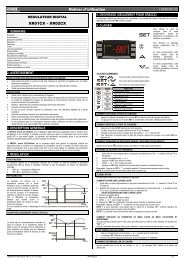
ENGLISH<br />
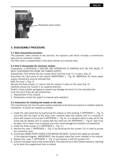
Backwash press button<br />
5. DISASSEMBLY PROCEDURE<br />
5.1 Valve disassembly procedure:<br />
The automatic valve consists of two sections, the hydraulic part which inclu<strong>de</strong>s a conventional<br />
valve and an automatic module.<br />
The fi lter valve is disassembled in the same manner as a manual valve.<br />
5.2 How to disassemble the electronic module:<br />
(illustrations in APPENDIX 1) BEFORE ANY OPERATION IS CARRIED OUT ON THE VALVE, IT<br />
MUST DISCONNECTED FROM THE POWER SUPPLY.<br />
Disassembly: First remove the four screws which hold the cover (1) in place. (Fig. 2).<br />
Disconnect all input wires to the module (AAPPENDIX 1 - Fig. 8). WARNING: All mains power<br />
supply connections must be removed fi rst.<br />
Refi t the cover 1 (Fig. 2)<br />
Remove the three screws (11) which hold the module in place on the valve (Fig. 3).<br />
Carefully remove the module in an upwards direction.<br />
Protect insi<strong>de</strong> suitable packaging to prevent any damage and send it to the manufacturer.<br />
From this point there are two possibilities:<br />
1. Replacement of the module.<br />
2. Temporarily convert the system to manual valve operation.<br />
5.3 Instructions for installing the module on the valve.<br />
The manufacturer will ship the valve-module assembly to the technical service or installer ready for<br />
installation. It should be installed as follows:<br />
1. Install the valve assembly by positioning the module so that marking 2 (APPENDIX 1 - Fig. 3)<br />
coinci<strong>de</strong>s with the mark on the valve cover, carefully lower the module until it is correctly in<br />
place with respect to the screw 3 (APPENDIX 1 - Fig. 4). In a situation where it does not fi t, the<br />
screw may be rotated until it couples with the motor pin (4) (APPENDIX 1 - Fig.4). Care must<br />
be taken not to lower it too brusquely since this could damage the module’s microswitches.<br />
2. Install the three screws (11) (APPENDIX 1 - Fig. 3 ).<br />
3. Remove the cover 1 (APPENDIX 1 - Fig. 2) by removing the four screws (13) in or<strong>de</strong>r to access<br />
the connection strip.<br />
4. Connection (MAKE SURE THERE IS NO MAINS VOLTAGE). Connect the cables as indicated<br />
in the attached diagram. IMPORTANT! Use the gland seals that come installed in the module.<br />
5. Replace the cover 1 (APPENDIX 1 - Fig. 2) and replace it with the screws (13).<br />
6. Connect the power input to the control board. The valve will be in the Filtration position, standing<br />
by for when the programmed time is entered.<br />
17