3B SCIENTIFIC® PHYSICS U10050 Stirlingmotor, transparent
3B SCIENTIFIC® PHYSICS U10050 Stirlingmotor, transparent
3B SCIENTIFIC® PHYSICS U10050 Stirlingmotor, transparent

Create successful ePaper yourself
Turn your PDF publications into a flip-book with our unique Google optimized e-Paper software.
3. Technical data<br />
Motor-generator unit:<br />
max. 12 V DC<br />
2-stage pulley:<br />
30 mm dia., 19 mm dia.<br />
Working piston:<br />
25 mm dia.<br />
Path of working piston:<br />
24 mm<br />
Volumetric change:<br />
⎛25 mm ⎞ 3<br />
24 mm ⎜ ⎟ ⋅π= 12 cm<br />
⎝ 2 ⎠<br />
Minimum volume:<br />
32 cm³<br />
Maximum volume:<br />
44 cm³<br />
Power of the Stirling motor:<br />
1 W approx.<br />
Dimensions:<br />
300x220x160 mm³ approx.<br />
Weight:<br />
1.65 kg approx.<br />
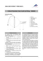
4. Functioning principle<br />
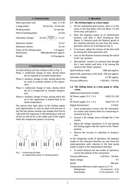
An ideal Stirling cycle has 4 phases (refer to Fig. 1):<br />
Phase 1: Isothermal change of state, during which<br />
the air expands at constant temperature.<br />
Phase 2: Isochoric change of state, during which the<br />
air cools at constant volume in the regenerator.<br />
Phase 3: Isothermal change of state, during which<br />
the air is compressed at constant temperature.<br />
Phase 4: Isochoric change of state, during which the<br />
air in the regenerator is heated back to its<br />
initial temperature.<br />
The process that takes place in the Stirling engine<br />
only approximates to such an ideal cycle because in<br />
fact the four phases overlap. Gas changes from hot to<br />
cold while the expansion is still taking place and not<br />
all the air will yet be in the colder part of the engine<br />
while the compression phase is occurring.<br />
Fig. 1<br />
Functioning principle<br />
(A: Displacement piston, B: Working piston)<br />
5. Operation<br />
5.1 The Stirling Engine as a heat engine<br />
• Fill the methylated-spirit burner, place it in the<br />
recess in the base-plate, twist out about 1-2 mm<br />
of the wick, and ignite it.<br />
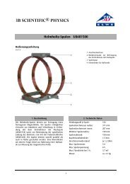
• Move the displacer piston to its farthest-back<br />
position, and after a short heating-up time<br />
(about 1-2 minutes) push the flywheel gently in<br />
the clockwise direction (as seen from the motorgenerator<br />
unit) to set it turning (see Fig. 2).<br />
• If necessary, adjust the tension of the drive belt<br />
by moving the motor-generator unit.<br />
• Turn on the filament lamp by moving the switch<br />
to the “up” position.<br />
• Alternatively, connect an external load through<br />
the 4 mm sockets and drive it by moving the<br />
switch to the “down” position.<br />
Speed without a load:<br />
1000 rpm approx.<br />
Speed with a generator as the load: 650 rpm approx.<br />
Generator voltage:<br />
6 V DC approx.<br />
Pressure difference:<br />
+250 hPa / -150 hPa<br />
5.2 The Stirling motor as a heat pump or refrigerator<br />
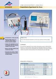
Additional instruments needed:<br />
DC Power supply 15 V, 1.5 A U8521121-230<br />
or<br />
DC Power supply 15 V, 1.5 A U8521121-115<br />
Digital thermometer<br />
U11818<br />
• Insert temperature sensors into the thermometer<br />
sockets and connect them to a measuring instrument<br />
(see fig. 3).<br />
• Connect a DC voltage source through the 4 mm<br />
sockets.<br />
• Adjust the voltage (maximum 12 V) and operate<br />
the Stirling engine with the switch in the “down”<br />
position.<br />
• Observe the increase or reduction in temperature.<br />
In the refrigerator mode of operation, the flywheeI<br />
rotates in the clockwise direction (as seen from the<br />
motor-generator unit), whereas in the heat pump<br />
mode it rotates in the anticlockwise direction.<br />
• To switch between the two modes of operation,<br />
reverse the polarity of the connections.<br />
Pressure difference:<br />
+250 hPa / -150 hPa<br />
Motor voltage:<br />
9 V<br />
Speed:<br />
600 rpm<br />
Temperature difference (with respect to 21° C):<br />
Refrigerator: -4 K (reservoir: +6 K)<br />
Heat pump: +13 K (reservoir: -1 K)<br />
2