Betriebsanleitung Elektronisches Handrad HKA/HKC - EUCHNER ...
Betriebsanleitung Elektronisches Handrad HKA/HKC - EUCHNER ...
Betriebsanleitung Elektronisches Handrad HKA/HKC - EUCHNER ...

Create successful ePaper yourself
Turn your PDF publications into a flip-book with our unique Google optimized e-Paper software.
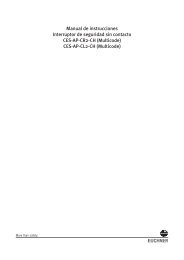
<strong>Betriebsanleitung</strong> <strong>Elektronisches</strong> <strong>Handrad</strong> <strong>HKA</strong>/<strong>HKC</strong><br />
Sicherheitshinweise<br />
<strong>EUCHNER</strong> Handräder <strong>HKA</strong>/<strong>HKC</strong> entsprechen den<br />
EMV-Schutzanforderungen nach EN 61000-6-2 und<br />
EN 61000-6-4.<br />
Handräder <strong>HKA</strong>/<strong>HKC</strong> dürfen nicht im Wohnbereich,<br />
in Geschäfts- und Gewerbebereichen sowie in Kleinbetrieben<br />
eingesetzt werden.<br />
Der Betreiber des übergeordneten Gesamtsystems<br />
ist für das Einhalten der für den speziellen Einsatzfall<br />
geltenden nationalen und internationalen<br />
Sicherheits- und Unfallvorschriften verantwortlich.<br />
Bei der Maschinenplanung und Verwendung von<br />
Handrädern sind die einsatzspezifischen nationalen<br />
und internationalen Sicherheits- und Unfallverhütungsvorschriften<br />
einzuhalten, wie z.B.:<br />
EN 60204, Elektrische Ausrüstung von Maschinen<br />
EN 12100, Sicherheit von Maschinen, allgemeine<br />
Gestaltungsleitsätze<br />
EN 13849, Sicherheitsbezogene Teile von Steuerungen<br />
Die Gefährdung von Menschen und die Beschädigung<br />
von Betriebseinrichtungen durch eine<br />
Fehlfunktion des <strong>Handrad</strong>es sind durch geeignete<br />
Sicherheitsmaßnahmen auszuschließen.<br />
Bestimmungsgemäßer Gebrauch<br />
Das <strong>Handrad</strong> von <strong>EUCHNER</strong> ist ein Universal-Impulsgeber<br />
zur manuellen Verstellung von Achsen.<br />
Das <strong>Handrad</strong> dient überwiegend zur Positionierung<br />
von NC-gesteuerten Werkzeugmaschinen im Einrichtebetrieb.<br />
Handräder werden als Bestandteil eines übergeordneten<br />
Gesamtsystems eingesetzt.<br />
Einsatz, Montage und Betrieb sind nur entsprechend<br />
dieser <strong>Betriebsanleitung</strong> zulässig.<br />
Nichtbestimmungsgemäßer Gebrauch<br />
Handräder allein dürfen nicht als Sicherheitselement<br />
zur Vermeidung von gefährdenden Zuständen<br />
in einer Maschinenanlage eingesetzt werden.<br />
Funktion<br />
Am Ausgang des <strong>Handrad</strong>es stehen dem Anwender<br />
wahlweise 100 bzw. 25 Rechteckimpulse pro<br />
Umdrehung zur Verfügung.<br />
Ein zweiter um 90° phasenverschobener Ausgang<br />
ermöglicht der nachgeschalteten Steuerung die Erkennung<br />
der Bewegungsrichtung.<br />
Die Auswertung der Impulse erfolgt in der Steuerung.<br />
Die Rastung ist magnetisch und somit absolut<br />
verschleißfrei.<br />
Montage<br />
Die Montage darf ausschließlich von autorisiertem<br />
Fachpersonal durchgeführt werden.<br />
Handräder nicht öffnen!<br />
Handräder nicht werfen oder fallen<br />
lassen!<br />
Keine Schläge auf die Handräder<br />
ausüben!<br />
Handräder nicht mechanisch bearbeiten!<br />
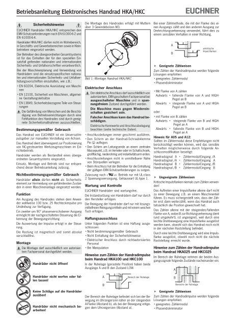
Die Montage des <strong>Handrad</strong>es erfolgt mit Muttern<br />
über 3 Gewindebolzen M3.<br />
Bild 1: Montage <strong>Handrad</strong> <strong>HKA</strong>/<strong>HKC</strong><br />
Elektrischer Anschluss<br />
Der elektrische Anschluss darf ausschließlich von<br />
autorisiertem, EMV-geschultem Fachpersonal bei<br />
ausgeschalteter Maschine und in spannungsfreiem<br />
Zustand durchgeführt werden.<br />
Die Maschine muss gegen Wiedereinschalten<br />
gesichert sein.<br />
Falscher Anschluss kann das <strong>Handrad</strong> beschädigen.<br />
Elektrische Kennwerte und Anschlussbelegung<br />
beachten (siehe technische Daten).<br />
Anschlussleitungen immer geschirmt ausführen.<br />
Den Schirm an der <strong>Handrad</strong>-Schraubklemme<br />
Pin auflegen.<br />
Den Schirm am Leitungsende an einem zentralen<br />
Massepunkt, z.B. im Verteiler oder im Schaltschrank,<br />
großflächig, niederohmig und induktivitätsarm erden.<br />
Anschlussleitungen nicht in unmittelbarer Nähe<br />
von Störquellen verlegen.<br />
Beim Anschluss hat der Betreiber für die Einhaltung<br />
der gültigen EMV-Schutzanforderungen zu sorgen.<br />
Zulassung nach : Betrieb nur mit UL-class<br />
2 Spannungsversorgung, Gehäuseart UL-type 1.<br />
Wartung und Kontrolle<br />
<strong>EUCHNER</strong> Handräder sind wartungsfrei.<br />
Die Instandsetzung von Handrädern darf nur durch<br />
den Hersteller erfolgen.<br />
Die Reinigung der Handräder darf nur mit lösungsmittelfreien<br />
Reinigungsmitteln und mit einem weichen<br />
Tuch erfolgen.<br />
Haftungsausschluss<br />
Unter folgenden Punkten ist eine Haftung ausgeschlossen:<br />
Nicht bestimmungsgemäßer Gebrauch<br />
Nicht Einhaltung der Sicherheitshinweise<br />
Elektrischer Anschluss durch nichtautorisiertes<br />
Personal<br />
Bei Manipulation<br />
Hinweise zum Zählen der <strong>Handrad</strong>impulse<br />
beim <strong>Handrad</strong> <strong>HKA</strong>100 und <strong>HKC</strong>100<br />
In der Ruhelage (gerastete Position) haben beide<br />
Ausgänge A und B den Zustand LOW.<br />
a b<br />
A<br />
Bereich der Ruhelage<br />
B<br />
Der Bereich der Ruhelage befindet sich bei der Bewegung<br />
im Uhrzeigersinn näher an der steigenden<br />
A-Flanke (Abstand b), als bei der Bewegung entgegen<br />
dem Uhrzeigersinn (Abstand a).<br />
Bei einer Zählmethode, die mit der Flanke des einen<br />
Ausgangs zählt und den anderen Ausgang zur<br />
Drehrichtungserkennung verwendet, führt dies zu<br />
einem sensiblen Verhalten in einer Richtung.<br />
A<br />
B<br />
Geeignete Zählweisen<br />
Zum Zählen der <strong>Handrad</strong>impulse werden folgende<br />
Lösungen empfohlen:<br />
geeignetes Zählermodul<br />
Phasendiskriminator<br />
Mit Flanke von A zählen<br />
Aufwärts fallende Flanke von A und HIGH-<br />
Pegel an B<br />
Abwärts steigende Flanke von A und HIGH-<br />
Pegel an B<br />
oder<br />
mit Flanke von B zählen<br />
Aufwärts steigende Flanke von B und HIGH-<br />
Pegel an A<br />
Abwärts fallende Flanke von B und HIGH-<br />
Pegel an A<br />
Hinweis für A05 und A12:<br />
Sollten im Zählermodul diese Empfehlungen nicht<br />
berücksichtigt werden können, wird das sensible<br />
Verhalten möglicherweise durch folgende Anschlussmodifikation<br />
beseitigt:<br />
<strong>Handrad</strong>signal A Zählermodul-Eingang /A<br />
<strong>Handrad</strong>signal /A Zählermodul-Eingang A<br />
<strong>Handrad</strong>signal B Zählermodul-Eingang /B<br />
<strong>Handrad</strong>signal /B Zählermodul-Eingang B<br />
Ungeeignete Zählweisen<br />
Kritische Impulsflanken niemals zum Zählen verwenden!<br />
Das Auftreten einer Impulsflanke alleine darf nicht<br />
zu einer Bewegung z.B. an einem Maschinenteil<br />
führen. Es muss sichergestellt sein, dass der Zähler<br />
erst dann weiterzählt, wenn das <strong>Handrad</strong> auch<br />
tatsächlich die Position gewechselt hat.<br />
Das Zählen alleine mit der steigenden/fallenden<br />
Flanke von A, wobei B zur Richtungserkennung dient<br />
(und umgekehrt), ist ungeeignet, weil durch eine<br />
leichte Drehbewegung eine Impulsflanke ausgelöst<br />
werden kann, obwohl sich das <strong>Handrad</strong> noch nicht<br />
in der nächsten Raststellung befindet.<br />
Durch eine leichte Drehbewegung wird eine Impulsflanke<br />
ausgelöst, obwohl noch nicht die nächste<br />
Raststellung erreicht wurde.<br />
Hinweise zum Zählen der <strong>Handrad</strong>impulse<br />
beim <strong>Handrad</strong> <strong>HKA</strong>025 und <strong>HKC</strong>025<br />
Im Bereich der Ruhelage nehmen die beiden Ausgangssignale<br />
folgende Zustände nacheinander ein:<br />
A<br />
B<br />
Geeignete Zählweisen<br />
Zum Zählen der <strong>Handrad</strong>impulse werden folgende<br />
Lösungen empfohlen:<br />
geeignetes Zählermodul<br />
Phasendiskriminator<br />
a<br />
a<br />
Bereiche der Ruhelage<br />
unkritische<br />
Impulsflanken
<strong>Betriebsanleitung</strong> <strong>Elektronisches</strong> <strong>Handrad</strong> <strong>HKA</strong>/<strong>HKC</strong><br />
Technische Daten<br />
Parameter<br />
Wert<br />
Impulse pro Umdrehung 2 x 25 oder 2 x 100<br />
Raststellungen 100<br />
Gehäusewerkstoff<br />
Thermoplast<br />
Masse<br />
0,25 kg<br />
Rastung<br />
magnetisch<br />
Wellenbelastung axial, max.<br />
25 N<br />
Wellenbelastung radial, max.<br />
40 N<br />
Lebensdauer mechanisch, min.<br />
20 x 10 6 U<br />
Betriebstemperatur 0 °C ... +50 °C<br />
Lagertemperatur -20 °C ... +50 °C<br />
Luftfeuchtigkeit, max.<br />
80 % (Betauung unzulässig)<br />
Schutzart frontseitig nach EN 60529 / IEC 529 IP 65<br />
nach NEMA 250-12<br />
Widerstandsfähigkeit Schwingungen (3 Achsen) DIN/IEC 68-2-6<br />
gegenüber Vibrationen Schock (3 Achsen) DIN/IEC 68-2-27<br />
EMV-Schutzanforderungen gemäß CE EN 61000-6-2, EN 61000-6-4<br />
Ausgangsschaltung<br />
Gegentakt<br />
Ausgangsstufe G05 G12 G24 Anschlussbelegung<br />
Ausgangssignale<br />
A, B<br />
Betriebsspannung U B<br />
DC 5 V ± 5 % DC 10 ... 30 V<br />
Betriebsstrom ohne Last, max.<br />
80 mA<br />
Ausgangsspezifikationen<br />
Ausgangsspannung HIGH (1), min. 4,0 V / 0 mA 4,9 V / 0 mA –<br />
3,4 V / 5 mA 3,9 V / 5 mA –<br />
3,0 V / 20 mA 3,6 V / 20 mA U B<br />
- 3 V / 20 mA<br />
LOW (0), max. 1,3 V / 15 mA 1,3 V / 15 mA 3 V / 20 mA<br />
Ausgangsstrom je Ausgang, max.<br />
20 mA<br />
Ausgangssignale<br />
25 Impulse 100 Impulse<br />
90˚<br />
360˚<br />
90˚<br />
360˚<br />
Schraubklemme 7-polig<br />
Adernquerschnitt<br />
0,08² ... 2,5²<br />
(AWG 28 ... 12)<br />
Anzugsdrehmoment<br />
max. 0,5 Nm<br />
Zu verwenden sind<br />
Kupferleiter mit einer<br />
Temperaturfestigkeit<br />
von 75°C<br />
Technische Änderungen vorbehalten, alle Angaben ohne Gewähr. © <strong>EUCHNER</strong> GmbH + Co. KG 089117-05-12/07<br />
A<br />
A<br />
U B<br />
0V A B<br />
B<br />
B<br />
Bereiche der Ruhelage<br />
Bereich der Ruhelage<br />
Ausgangsschaltung<br />
RS422<br />
Ausgangsstufe A05 A12 Anschlussbelegung<br />
Ausgangssignale A, /A, B, /B<br />
Betriebsspannung U B<br />
DC 5 V ± 5 % DC 10 ... 30 V<br />
Betriebsstrom ohne Last, max.<br />
80 mA<br />
Ausgangsspezifikationen<br />
entsprechend RS422A<br />
Ausgangssignale<br />
25 Impulse 100 Impulse<br />
A<br />
/A<br />
90˚<br />
360˚<br />
A<br />
/A<br />
90˚<br />
360˚<br />
Schraubklemme 7-polig<br />
Adernquerschnitt<br />
0,08² ... 2,5²<br />
(AWG 28 ... 12)<br />
Anzugsdrehmoment<br />
max. 0,5 Nm<br />
Zu verwenden sind<br />
Kupferleiter mit einer<br />
Temperaturfestigkeit<br />
von 75°C<br />
B<br />
/B<br />
B<br />
/B<br />
Bereiche der Ruhelage<br />
Bereich der Ruhelage<br />
<strong>Handrad</strong> <strong>HKA</strong><br />
<strong>Handrad</strong> <strong>HKC</strong><br />
Schalttafelausschnitt<br />
M3<br />
9<br />
6,5<br />
34<br />
24<br />
3,5<br />
45<br />
∅ 61<br />
∅ 3,4<br />
R 41<br />
∅ 60<br />
∅ 60<br />
M3<br />
∅ 63<br />
∅ 78<br />
∅ 80<br />
45<br />
U B<br />
0V A /A B /B<br />
30 28<br />
40<br />
Bild 2: Maßzeichnungen Handräder <strong>HKA</strong>/<strong>HKC</strong><br />
8,5<br />
∅ 72<br />
<strong>EUCHNER</strong> GmbH + Co. KG Kohlhammerstraße 16 D-70771 Leinfelden-Echterdingen Tel. +49/711/75 97-0 Fax +49/711/75 33 16 www.euchner.de info@euchner.de
Operating instructions for electronic handwheel <strong>HKA</strong>/<strong>HKC</strong><br />
Safety precautions<br />
<strong>EUCHNER</strong> handwheels <strong>HKA</strong>/<strong>HKC</strong> meet the EMC<br />
protection requirements according to EN 61000-6-2<br />
and EN 61000-6-4.<br />
<strong>HKA</strong>/<strong>HKC</strong> handwheel must not be used for residential<br />
applications, in business or commercial areas or<br />
in small business.<br />
The operator of the overall higher-level system is<br />
responsible for conformity with the national and<br />
international safety and accident prevention regulations<br />
applicable to the special application.<br />
When designing machines and using handwheels,<br />
the national and international safety and accident<br />
prevention regulations specific to the application<br />
must be observed, e.g.:<br />
EN 60204, electrical equipment of machines<br />
EN 12100, safety of machines, general design<br />
principles<br />
EN 13849, safety-related parts of control<br />
systems<br />
Appropriate safety measures must be taken<br />
to prevent a malfunction of the handwheel<br />
which could cause danger to human beings or<br />
damage to operating equipment.<br />
Correct use<br />
The <strong>EUCHNER</strong> handwheel is a universal pulse<br />
generator for manual shaft positioning.<br />
The handwheel is primarily used for positioning NCdriven<br />
machine tools during set-up.<br />
Handwheels are used as part of an overall higherlevel<br />
control system.<br />
Their use, installation and operation are permissible<br />
only in conformity with these Operating Instructions.<br />
Incorrect use<br />
Handwheels on their own must not be used as<br />
safety components for avoiding hazardous states<br />
in a machine installation.<br />
Function<br />
Two square-wave outputs of 100 or 25 pulses per<br />
revolution are available for the user.<br />
A second output phase-shifted by 90° allows the<br />
connected control to detect the direction of movement.<br />
The pulses are evaluated in the control.<br />
The detent mechanism is magnetic and is therefore<br />
totally wear-free.<br />
Assembly<br />
The unit may only be assembled by authorised<br />
personnel.<br />
Do not open the handwheels!<br />
Do not throw or drop the<br />
handwheels!<br />
Do not hit the handwheels!<br />
Do not use tools on the handwheels!<br />
The handwheel is assembled with nuts on 3 threaded<br />
M3 bolts.<br />
Fig. 1: Assembly of handwheel <strong>HKA</strong>/<strong>HKC</strong><br />
Electrical connection<br />
Electrical connection may only be performed by<br />
authorised personnel trained in EMC with the<br />
machine switched off and in de-energised<br />
state.<br />
The machine must be safeguarded against<br />
reactivation.<br />
If connected incorrectly, the handwheel<br />
may be damaged.<br />
Observe electrical characteristics and the pin<br />
assignments (see technical data)<br />
Always shield connecting leads.<br />
Apply shielding to handwheel screw terminal pin<br />
.<br />
Ground the shield at the end of the lead at a central<br />
grounding point, e.g. in the distribution board<br />
or in the control cabinet, over a large surface,<br />
with low resistance and with low inductance.<br />
Do not install connecting leads in the immediate<br />
vicinity of interference sources.<br />
When installing connections, the operator must<br />
ensure compliance with the EMC safety requirements.<br />
Authorisation according to : operation with<br />
power supply of UL-class 2 only, housing type<br />
UL-type 1.<br />
Service and inspection<br />
<strong>EUCHNER</strong> handwheels require no maintenance.<br />
Handwheels may only be repaired by the manufacturer.<br />
To clean the handwheels, only use solvent-free<br />
cleaning agents and a soft cloth.<br />
Disclaimer of liability<br />
The company does not accept liability regarding<br />
the following cases:<br />
if the unit is not used for its intended purpose<br />
if the safety instructions are not followed<br />
if the units are electrically connected by unauthorised<br />
personnel<br />
if the units are tampered with<br />
Instructions for counting the handwheel<br />
pulses: Handwheel <strong>HKA</strong>100 and <strong>HKC</strong>100<br />
In the home position (detent position), outputs A<br />
and B are both in the LOW state.<br />
A<br />
B<br />
a<br />
When it moves clockwise, the home position area is<br />
located closer to the rising edge of A (distance b)<br />
than when it moves counter-clockwise (distance a).<br />
b<br />
Home position area<br />
Using a counting method which counts with the<br />
edge of the output and uses the other output for<br />
detecting the direction of rotation can result in sensitive<br />
behaviour in one direction.<br />
A<br />
B<br />
Suitable counting methods<br />
The following options are recommended for counting<br />
the handwheel pulses:<br />
suitable counter module<br />
phase discriminator<br />
Count with the edge of A<br />
Ascending falling edge from A and HIGH<br />
level at B<br />
Descending <br />
a<br />
rising edge from A and HIGH<br />
level at B<br />
or<br />
Count with the edges of B<br />
Ascending rising edge from B and HIGH<br />
level at A<br />
Descending falling edge from B and HIGH<br />
level at A<br />
Note for A05 and A12:<br />
If the recommended counting method does not<br />
function properly, the signal behavior may be remedied<br />
by changing the following connection:<br />
Handwheel signal A Counter module input /A<br />
Handwheel signal/A Counter module input A<br />
Handwheel signal B Counter module input/B<br />
Handwheel signal/B Counter module input B<br />
Unsuitable counting methods<br />
Never use critical pulse edges for counting!<br />
On its own, the occurrence of a pulse edge must<br />
not result in movement, e.g. of a machine component.<br />
Care must be taken to ensure that the counter<br />
does not increment until the position of the handwheel<br />
has actually changed.<br />
Counting with the rising/falling edge of A - where B<br />
assists the direction detection (and vice versa) - is<br />
not suitable, because a pulse edge may be<br />
triggered by a slight rotation even though the<br />
handwheel has not yet reached the next detent<br />
position.<br />
A pulse edge is triggered by slight rotation even<br />
though the next detent position has not yet been<br />
reached.<br />
Instructions for counting the handwheel<br />
pulses: Handwheel <strong>HKA</strong>025 and <strong>HKC</strong>025<br />
In the home position area, the two output signals<br />
assume the following states in sequence.<br />
A<br />
B<br />
Suitable counting methods<br />
The following options are recommended for<br />
counting the handwheel pulses:<br />
suitable counter module<br />
phase discriminator<br />
a<br />
Home position areas<br />
Uncritical<br />
pulse edges
Operating instructions for electronic handwheel <strong>HKA</strong>/<strong>HKC</strong><br />
Technical data<br />
Parameters<br />
Value<br />
Pulses per revolution 2 x 25 or 2 x 100<br />
Detent positions 100<br />
Housing material<br />
Thermoplastic<br />
Weight<br />
0.25 kg<br />
Detent mechanism<br />
Magnetic<br />
Shaft loading, axial, max.<br />
25 N<br />
Shaft loading, radial, max.<br />
40 N<br />
Mechanical service life, min.<br />
20 x 10 6 U<br />
Operating temperature 0 °C ... +50 °C<br />
Storage temperature -20 °C ... +50 °C<br />
Humidity, max.<br />
80 % (condensation not permissible)<br />
Degree of protection to the front In accordance with EN 60529 / IEC 529 IP 65<br />
In accordance with NEMA 250-12<br />
Resistance to Vibrations (3 axes) DIN/IEC 68-2-6<br />
vibration Shock (3 axes) DIN/IEC 68-2-27<br />
EMC protection requirements in acc. with CE EN 61000-6-2, EN 61000-6-4<br />
Output circuit<br />
Push-pull<br />
Output stage G05 G12 G24 Pin assignment<br />
Output signals<br />
A, B<br />
Operating voltage U B<br />
DC 5 V ± 5 % DC 10 ... 30 V<br />
Operating current, no load, max.<br />
80 mA<br />
Output specifications<br />
Output voltage HIGH (1), min. 4.0 V / 0 mA 4.9 V / 0 mA -<br />
3.4 V / 5 mA 3.9 V / 5 mA -<br />
3.0 V / 20 mA 3.6 V / 20 mA U B<br />
- 3 V / 20 mA<br />
LOW (0), max. 1.3 V / 15 mA 1.3 V / 15 mA 3 V / 20 mA<br />
Output current per output, max.<br />
20 mA<br />
Output signals<br />
25 pulses 100 pulses<br />
A<br />
B<br />
Home position areas<br />
Home position area<br />
Output circuit<br />
RS422<br />
Output stage A05 A12 Pin assignment<br />
Output signals A, /A, B, /B<br />
Operating voltage U B<br />
DC 5 V ± 5 % DC 10 ... 30 V<br />
Operating current, no load, max.<br />
80 mA<br />
Output specifications<br />
In accordance with RS422A<br />
Output signals<br />
25 pulses 100 pulses<br />
A<br />
/A<br />
90˚<br />
90˚<br />
360˚<br />
360˚<br />
A<br />
B<br />
A<br />
/A<br />
90˚<br />
90˚<br />
360˚<br />
360˚<br />
Screw terminal 7-pole<br />
Wire cross-section<br />
0.08² ... 2.5²<br />
(AWG 28 ... 12)<br />
Tightening torque<br />
max. 0.5 Nm<br />
It is necessary to use<br />
copper conductors with<br />
temperature resistance<br />
of 75°C<br />
U B<br />
0V A B<br />
Screw terminal 7-pole<br />
Wire cross-section<br />
0.08² ... 2.5²<br />
(AWG 28 ... 12)<br />
Tightening torque<br />
max. 0.5 Nm<br />
It is necessary to use<br />
copper conductors with<br />
temperature resistance<br />
of 75°C<br />
Subject to technical modifications; no responsibility is accepted for the accuracy of this information. © <strong>EUCHNER</strong> GmbH + Co. KG 089117-05-12/07<br />
B<br />
/B<br />
B<br />
/B<br />
Home position areas<br />
Home position area<br />
Handwheel <strong>HKA</strong><br />
Handwheel <strong>HKC</strong><br />
Front panel cut-out<br />
M3<br />
9<br />
6,5<br />
34<br />
24<br />
3,5<br />
45<br />
∅ 61<br />
∅ 3,4<br />
R 41<br />
∅ 60<br />
∅ 60<br />
M3<br />
∅ 63<br />
∅ 78<br />
∅ 80<br />
45<br />
U B<br />
0V A /A B /B<br />
30 28<br />
40<br />
Fig. 2: Dimension drawings of handwheel <strong>HKA</strong>/<strong>HKC</strong><br />
8,5<br />
∅ 72<br />
<strong>EUCHNER</strong> GmbH + Co. KG Kohlhammerstraße 16 D-70771 Leinfelden-Echterdingen Tel. +49/711/75 97-0 Fax +49/711/75 33 16 www.euchner.de info@euchner.de
Mode d’emploi de la manivelle électronique <strong>HKA</strong>/<strong>HKC</strong><br />
Consignes de sécurité<br />
Les manivelles électroniques <strong>HKA</strong>/<strong>HKC</strong> de <strong>EUCHNER</strong><br />
répondent aux exigences de protection CEM<br />
conformément à EN 61000-6-2 et EN 61000-6-4.<br />
Les manivelles électroniques <strong>HKA</strong>/<strong>HKC</strong> ne doivent<br />
pas être installées dans des quartiers résidentiels,<br />
des zones commerciales et d’affaires ainsi que<br />
dans des commerces.<br />
L’exploitant du système complet est responsable du<br />
respect des normes nationales et internationales en<br />
matière de sécurité et de prévention des accidents<br />
en vigueur pour les applications spéciales.<br />
A la conception de la machine, lors de l’utilisation<br />
de manivelles électroniques, les normes nationales<br />
et internationales de sécurité et de prévention<br />
d’accidents doivent être respectées, comme par<br />
exemple :<br />
EN 60204, Equipement électrique des machines<br />
EN 12100, Sécurité des machines, principes<br />
généraux de conception<br />
EN 13849, Parties des systèmes de commande<br />
relatives à la sécurité<br />
Des mesures de sécurité appropriées doivent<br />
être prises afin d’éliminer tout danger pour les<br />
personnes et tout dommage sur l’outillage<br />
provoqués par un défaut de fonctionnement<br />
de la manivelle électronique.<br />
Utilisation conforme<br />
La manivelle électronique <strong>EUCHNER</strong> est un générateur<br />
d’impulsions universel destiné au déplacement<br />
manuel des axes.<br />
Elle est destinée en premier lieu au positionnement en<br />
mode réglage des machines-outils pilotées par CN.<br />
Les manivelles font partie intégrante d’un système<br />
global.<br />
La mise en service, le montage et le fonctionnement<br />
ne sont autorisés qu’en respectant ce mode d’emploi.<br />
Utilisation non conforme<br />
Les manivelles électroniques ne doivent pas être<br />
les seuls éléments de sécurité devant éviter les<br />
situations dangereuses sur une machine.<br />
Fonction<br />
A la sortie, l’utilisateur dispose resp. de 100 ou<br />
25 impulsions par tour (signal carré).<br />
Une autre sortie, déphasée de 90°, permet à la<br />
commande placée en aval de détecter le sens de<br />
déplacement.<br />
L’analyse des impulsions s’effectue au niveau de<br />
la commande.<br />
Le crantage est magnétique et donc absolument<br />
inusable.<br />
Montage<br />
Le montage doit être effectué exclusivement par<br />
un personnel habilité.<br />
Ne pas ouvrir !<br />
Ne pas jeter, ni laisser tomber !<br />
Ne pas heurter !<br />
Ne pas modifier mécaniquement !<br />
Le montage de la manivelle électronique s’effectue<br />
grâce à des écrous via 3 goujons M3.<br />
Fig. 1 : montage de la manivelle électronique <strong>HKA</strong>/<strong>HKC</strong><br />
Raccordement électrique<br />
Le raccordement électrique doit être effectué<br />
exclusivement par un personnel habilité et<br />
formé à la CEM, sur une machine hors<br />
tension et déconnectée<br />
Prendre les mesures nécessaires pour<br />
éviter une remise en route intempestive.<br />
Un raccordement incorrect peut endommager<br />
la manivelle électronique.<br />
Respecter les paramètres électriques et<br />
l’affectation des broches (voir caractéristiques<br />
techniques).<br />
Les câbles de raccordement doivent toujours être<br />
blindés.<br />
Raccorder le blindage au niveau de la broche <br />
de la borne à vis.<br />
Le blindage des câbles doit être mis à la terre au<br />
niveau d’une masse centrale, par ex. dans le coffret<br />
répartiteur ou l’armoire électrique, en assurant une<br />
surface de contact suffisante et en respectant des<br />
conditions d’impédance et d’inductance faibles.<br />
Ne pas poser les câbles de raccordement à proximité<br />
de sources parasites.<br />
Lors du raccordement, l’utilisateur doit veiller au<br />
respect des exigences de protection CEM.<br />
Homologation : fonctionnement uniquement<br />
avec alimentation UL-class 2, type de boîtier UL-type 1.<br />
Entretien et contrôle<br />
Les manivelles électroniques <strong>EUCHNER</strong> ne nécessitent<br />
pas d’entretien.<br />
Seul <strong>EUCHNER</strong> est habilité à leur réparation.<br />
Le nettoyage doit être effectué uniquement avec<br />
des produits de nettoyage sans solvant et avec un<br />
chiffon doux.<br />
Exclusion de responsabilité<br />
Les points suivants ne relèvent pas de la responsabilité<br />
du fabricant :<br />
Utilisation non conforme<br />
Non-respect des consignes de sécurité<br />
Raccordement électrique par du personnel non<br />
habilité<br />
En cas d’intervention extérieure sur la manivelle<br />
Indications pour le comptage des impulsions<br />
de manivelle pour <strong>HKA</strong>100 et <strong>HKC</strong>100<br />
En zone de repos, les 2 sorties A et B sont en<br />
niveau bas.<br />
a b<br />
A<br />
Zone de repos<br />
B<br />
La zone de repos est plus proche du front montant A<br />
(distance b) lors du mouvement dans le sens horaire que<br />
lors du mouvement dans le sens anti-horaire (distance a).<br />
La méthode de comptage, consistant à utiliser le<br />
front d’une sortie pour le comptage et l’autre sortie<br />
pour détecter le sens de rotation, conduit à un<br />
comportement sensible dans un sens.<br />
A<br />
B<br />
Méthodes de comptage adaptées<br />
Les solutions suivantes sont recommandées pour<br />
compter les impulsions :<br />
Module de comptage adapté<br />
Discriminateur de phase<br />
Comptage avec le front d’impulsion de A<br />
Incrémentation front descendant de A et<br />
niveau haut sur B<br />
Décrémentation front ascendant de A et<br />
niveau haut sur B<br />
ou<br />
Comptage avec le front d’impulsion de B<br />
Incrémentation front ascendant de B et<br />
niveau haut sur A<br />
Décrémentation front descendant de B et<br />
niveau haut sur A<br />
Remarque pour A05 et A12 :<br />
Si ces recommandations ne pouvaient être prises<br />
en compte dans le module de comptage, le<br />
comportement sensible peut être corrigé par la<br />
modification de raccord suivante :<br />
Signal manivelle A Entrée module de comptage/ A<br />
Signal manivelle/ A Entrée module de comptage A<br />
Signal manivelle B Entrée module de comptage/ B<br />
Signal manivelle/ B Entrée module de comptage B<br />
Méthodes de comptage inadaptées<br />
Ne jamais utiliser des fronts d’impulsion critiques<br />
pour le comptage !<br />
L’apparition d’un front d’impulsion unique ne doit<br />
pas, par exemple, conduire au déplacement d’un<br />
composant de la machine. Il faut s’assurer que le<br />
compteur ne continue à s’incrémenter que si la<br />
manivelle a effectivement changé la position.<br />
Le comptage seul en utilisant le front ascendant/<br />
descendant de A, avec B servant à la détection du<br />
sens de rotation (et vice-versa), est inadapté, car<br />
un léger mouvement de rotation peut provoquer<br />
l’apparition d’un front d’impulsion, bien que la<br />
manivelle ne se trouve pas encore dans la position<br />
de crantage suivante.<br />
Un léger mouvement de rotation provoque l’apparition<br />
d’un front d’impulsion, bien que la position de crantage<br />
suivante n’ait pas encore été atteinte.<br />
Indications pour le comptage des impulsions<br />
de manivelle pour <strong>HKA</strong>025 et <strong>HKC</strong>025<br />
En zone de repos, les deux signaux de sortie<br />
adoptent successivement les états suivants :<br />
A<br />
B<br />
Méthodes de comptage adaptées<br />
Les solutions suivantes sont recommandées pour<br />
compter les impulsions :<br />
Module de comptage adapté<br />
Discriminateur de phase<br />
a<br />
a<br />
Zones de repos<br />
Fronts<br />
d’impulsion<br />
non critiques
Mode d’emploi de la manivelle électronique <strong>HKA</strong>/<strong>HKC</strong><br />
Caractéristiques techniques<br />
Paramètre<br />
Valeur<br />
Impulsions par tour 2 x 25 ou 2 x 100<br />
Nombre de positions par tour 100<br />
Matériau du boîtier<br />
thermoplastique<br />
Masse<br />
0,25 kg<br />
Crantage<br />
magnétique<br />
Charge axiale max. sur l’arbre<br />
25 N<br />
Charge radiale max. sur l’arbre<br />
40 N<br />
Durée de vie mécanique, min.<br />
20 x 10 6 U<br />
Température de service 0 °C ... +50 °C<br />
Température de stockage -20 °C ... +50 °C<br />
Humidité de l’air, max.<br />
80 % (condensation interdite)<br />
Indice de protection face avant selon EN 60529 / IEC 529 IP 65<br />
selon NEMA 250-12<br />
Résistance Vibrations (3 axes) DIN/IEC 68-2-6<br />
aux vibrations Choc (3 axes) DIN/IEC 68-2-27<br />
Exigences de protection CEM selon CE EN 61000-6-2, EN 61000-6-4<br />
Sortie<br />
symétrique<br />
Etage de sortie G05 G12 G24 Brochage<br />
Signaux de sortie<br />
A, B<br />
Tension de service U B<br />
DC 5 V ± 5 % DC 10 ... 30 V<br />
Courant de service sans charge, max.<br />
80 mA<br />
Spécifications de sortie<br />
Tension de sortie HIGH (1), min. 4,0 V / 0 mA 4,9 V / 0 mA -<br />
3,4 V / 5 mA 3,9 V / 5 mA -<br />
3,0 V / 20 mA 3,6 V / 20 mA U B<br />
- 3 V / 20 mA<br />
LOW (0), max. 1,3 V / 15 mA 1,3 V / 15 mA 3 V / 20 mA<br />
Courant de sortie, max. par sortie<br />
20 mA<br />
Signaux de sortie<br />
25 impulsions 100 impulsions<br />
A<br />
90˚<br />
360˚<br />
A<br />
90˚<br />
360˚<br />
7 bornes à vis<br />
Section des conducteurs<br />
0,08² ... 2,5²<br />
(AWG 28 ... 12)<br />
Couple de serrage<br />
max. 0,5 Nm<br />
Veillez à utiliser<br />
des conducteurs en cuivre<br />
avec une<br />
stabilité de température<br />
de 75°C<br />
U B<br />
0V A B<br />
Sous réserve de modifications techniques, indications non contractuelles. © <strong>EUCHNER</strong> GmbH + Co. KG 089117-05-12/07<br />
B<br />
B<br />
Zones de repos<br />
Zone de repos<br />
Sortie<br />
RS422<br />
Etage de sortie A05 A12 Brochage<br />
Signaux de sortie A, /A, B, /B<br />
Tension de service U B<br />
DC 5 V ± 5 % DC 10 ... 30 V<br />
Courant de service sans charge, max.<br />
80 mA<br />
Spécifications de sortie<br />
correspond à RS422A<br />
Signaux de sortie<br />
25 impulsions 100 impulsions<br />
A<br />
/A<br />
90˚<br />
360˚<br />
A<br />
/A<br />
90˚<br />
360˚<br />
7 bornes à vis<br />
Section des conducteurs<br />
0,08² ... 2,5²<br />
(AWG 28 ... 12)<br />
Couple de serrage<br />
max. 0,5 Nm<br />
Veillez à utiliser<br />
des conducteurs en cuivre<br />
avec une<br />
stabilité de température<br />
de 75°C<br />
B<br />
/B<br />
B<br />
/B<br />
Zones de repos<br />
Zone de repos<br />
Manivelle électronique <strong>HKA</strong><br />
Manivelle électronique <strong>HKC</strong><br />
Découpe pour pupitre<br />
M3<br />
9<br />
6,5<br />
34<br />
24<br />
3,5<br />
45<br />
∅ 61<br />
∅ 3,4<br />
R 41<br />
∅ 60<br />
∅ 60<br />
M3<br />
∅ 63<br />
∅ 78<br />
∅ 80<br />
45<br />
U B<br />
0V A /A B /B<br />
30 28<br />
40<br />
Fig. 2 : dimensions des manivelles électroniques <strong>HKA</strong>/<strong>HKC</strong><br />
8,5<br />
∅ 72<br />
<strong>EUCHNER</strong> GmbH + Co. KG Kohlhammerstraße 16 D-70771 Leinfelden-Echterdingen Tél. +49/711/75 97-0 Fax +49/711/75 33 16 www.euchner.de info@euchner.de
Istruzioni di impiego volantino elettronico <strong>HKA</strong>/<strong>HKC</strong><br />
Avvertenze di sicurezza<br />
I volantini <strong>EUCHNER</strong> <strong>HKA</strong>/<strong>HKC</strong> sono conformi alla<br />
normativa EMV secondo EN 61000-6-2 e EN 61000-6-4.<br />
Non utilizzare i volantini <strong>HKA</strong>/<strong>HKC</strong> in abitazioni,<br />
negozi, aree commerciali e piccole aziende.<br />
L’utilizzo del dispositivo è soggetto all’osservanza<br />
delle norme nazionali ed internazionali in tema di<br />
sicurezza e di prevenzione infortuni di cui è responsabile<br />
il gestore del sistema.<br />
Nella progettazione degli impianti e nell’utilizzo dei<br />
volantini devono essere rispettate le norme nazionali<br />
ed internazionali di sicurezza e di prevenzione<br />
degli infortuni per casi specifici, come ad esempio:<br />
EN 60204, equipaggiamento elettrico delle macchine<br />
EN 12100, Sicurezza delle macchine, principi<br />
costruttivi generali<br />
EN 13849, Componenti di sicurezza dei comandi.<br />
Adeguate misure di sicurezza nella costruzione<br />
dei volantini permettono di escludere guasti<br />
di funzionamento che possano causare lesioni<br />
alle persone e danni alle attrezzature.<br />
Impiego conforme alla destinazione d’uso<br />
Il volantino <strong>EUCHNER</strong> è un generatore di impulsi<br />
universale per la regolazione manuale degli assali.<br />
Esso serve prevalentemente per il posizionamento<br />
delle macchine utensili con controllo NC in fase di<br />
configurazione.<br />
I volantini sono componenti che vengono inseriti in<br />
sistemi di automazione.<br />
L’utilizzo, l’installazione ed il funzionamento devono<br />
avvenire esclusivamente secondo quanto riportato<br />
nelle istruzioni di impiego.<br />
Impiego non conforme alla destinazione d’uso<br />
I volantini non possono essere impiegati singolarmente<br />
come componenti di sicurezza per la<br />
segnalazione di situazioni di pericolo in macchine<br />
o impianti.<br />
Funzionamento<br />
All’uscita, il volantino fornisce 100 o 25 impulsi ad<br />
onda quadra per giro.<br />
Una seconda uscita sfasata di 90° consente ai sistemi<br />
di controllo collegati in serie di riconoscere<br />
la direzione del moto.<br />
La valutazione degli impulsi avviene nel comando.<br />
La ritenuta è magnetica e quindi assolutamente<br />
esente da usura.<br />
Installazione<br />
L’installazione deve essere eseguita esclusivamente<br />
da personale specializzato autorizzato.<br />
Non aprire il volantino!<br />
Evitare cadute del volantino!<br />
Non colpire il volantino.<br />
L’installazione del volantino elettronico avviene con<br />
3 dadi e 3 viti M3.<br />
Fig. 1: Installazione volantino <strong>HKA</strong>/<strong>HKC</strong><br />
Collegamento elettrico<br />
Il collegamento elettrico deve essere eseguito<br />
esclusivamente da tecnici autorizzati e con<br />
addestramento EMC a macchina spenta e in<br />
mancanza di tensione.<br />
La macchina deve essere messa in condizione<br />
da non potersi ripartire accidentalmente.<br />
Dei collegamenti difettosi possono danneggiare<br />
il volantino.<br />
Prestare attenzione alle caratteristiche elettriche<br />
e allo schema di collegamento (vedere<br />
dati tecnici).<br />
Realizzare sempre collegamenti con cavi schermati.<br />
Collegare la schermatura al morsetto a vite, pin<br />
.<br />
È necessario assicurare la messa a terra della<br />
schermatura dei cavi in un punto massa centrale, ad<br />
esempio nel ripartitore o nel quadro elettrico,<br />
caratterizzato da ampia superficie, bassa resistenza<br />
e ridotto carico induttivo.<br />
Non posare i cavi di collegamento in prossimità<br />
di fonti di disturbo.<br />
Durante il collegamento, l’utente deve attenersi<br />
alla normativa EMV.<br />
Autorizzazione secondo : impiego esclusivo<br />
con alimentazione di tensione classe UL 2,<br />
alloggiamento UL tipo 1.<br />
Manutenzione e controllo<br />
I volantini elettronici <strong>EUCHNER</strong> non richiedono<br />
manutenzione.<br />
Gli interventi di riparazione sui volantini devono<br />
essere eseguiti solo dalla <strong>EUCHNER</strong>.<br />
La pulizia dei volantini può essere eseguita esclusivamente<br />
con detergenti privi di solventi e con un<br />
panno morbido.<br />
Esonero delle responsabilità<br />
L’esonero della responsabilità avviene in presenza<br />
delle seguenti condizioni:<br />
impiego non conforme alla destinazione d’uso<br />
non ottemperanza con le istruzioni relative alla<br />
sicurezza<br />
collegamento elettrico eseguito da personale non<br />
autorizzato<br />
modifiche<br />
Note per il calcolo degli impulsi del<br />
volantino elettronico <strong>HKA</strong>100 e <strong>HKC</strong>100<br />
In stato/posizione di riposo, entrambe le uscite A<br />
e B si trovano in stato LOW.<br />
L’intervallo della posizione di riposo, con movimento<br />
in senso orario, è più prossimo al fianco ascendente<br />
A (intervallo b) rispetto a quando il movimento<br />
avviene in senso antiorario (intervallo a).<br />
Un metodo di calcolo che utilizzi il fianco di un’uscita<br />
per il conteggio e l’altra uscita per il riconoscimento<br />
della direzione di rotazione, porta ad un comportamento<br />
particolarmente sensibile in una direzione.<br />
a<br />
A<br />
Fianchi degli<br />
a impulsi<br />
B<br />
non critici<br />
Modalità di calcolo appropriate<br />
Per il calcolo degli impulsi del volantino si consigliano<br />
le seguenti soluzioni:<br />
Modulo di conteggio appropriato<br />
Discriminatore di fase<br />
Calcolo con il fianco A<br />
Avanti Fronte di discesa di A e livello HIGH di B<br />
Indietro Fronte di risalita di A e livello HIGH di B<br />
oppure<br />
Calcolo con il fianco B<br />
Avanti Fronte di risalita di B e livello HIGH di A<br />
Indietro Fronte di discesa di B e livello HIGH di A<br />
Nota per A05 e A12:<br />
Nel caso in cui non fosse possibile osservare tali<br />
avvertenze nel modulo di conteggio, è possibile<br />
eliminare tale „sensibilità“ effettuando la seguente<br />
modifica di collegamento:<br />
Segnale volantino elettronico A<br />
Ingresso modulo di conteggio /A<br />
Segnale volantino elettronico /A<br />
Ingresso modulo di conteggio A<br />
Segnale volantino elettronico B<br />
Ingresso modulo di conteggio /B<br />
Segnale volantino elettronico /B<br />
Ingresso modulo di conteggio B<br />
Modalità di calcolo non appropriate<br />
Non impiegare mai i fianchi degli impulsi critici per<br />
il calcolo.<br />
La presenza di un solo fronte degli impulsi non deve<br />
causare movimenti, ad esempio di un elemento<br />
della macchina. Accertarsi che il contatore continui<br />
il conteggio solo dopo l’effettiva modifica della<br />
posizione del volantino.<br />
Il calcolo con il solo fronte di risalita/di discesa di A,<br />
in cui B serve per il riconoscimento della direzione (e<br />
viceversa), non è appropriato in quanto un leggero<br />
movimento rotatorio può azionare un fronte degli<br />
impulsi, sebbene il volantino elettronico non abbia<br />
ancora raggiunto la successiva posizione di riposo.<br />
Con un leggero movimento rotatorio si attiva un<br />
fronte degli impulsi, sebbene non sia stata ancora<br />
raggiunta la successiva posizione di riposo.<br />
Note per il calcolo degli impulsi del<br />
volantino elettronico <strong>HKA</strong>025 e <strong>HKC</strong>025<br />
Nell’intervallo della posizione di riposo, i due segnali<br />
di uscita assumono nell’ordine le seguenti<br />
condizioni:<br />
A<br />
B<br />
Intervalli della posizione di riposo<br />
Non modificare meccanicamente<br />
il volantino.<br />
A<br />
B<br />
a<br />
b<br />
Intervallo della posizione<br />
di riposo<br />
Modalità di calcolo appropriate<br />
Per il calcolo degli impulsi del volantino si consigliano<br />
le seguenti soluzioni:<br />
Modulo di conteggio appropriato<br />
Discriminatore di fase
Istruzioni di impiego volantino elettronico <strong>HKA</strong>/<strong>HKC</strong><br />
Dati tecnici<br />
Parametri<br />
Valore<br />
Impulsi per rotazione 2 x 25 o 2 x 100<br />
Posizioni di riposo 100<br />
Materiale custodia<br />
Termoplastica<br />
Massa<br />
0,25 kg<br />
Ritenuta<br />
magnetica<br />
Carico applicato sull’albero assiale, max.<br />
25 N<br />
Carico applicato sull’albero radiale, max.<br />
40 N<br />
Durata meccanica, min.<br />
20 x 10 6 U<br />
Temperatura d’esercizio<br />
0°C ... +50°C<br />
Temperatura di magazzinaggio<br />
-20°C ... +50°C<br />
Umidità dell’aria, max.<br />
80% (condensa non ammissibile)<br />
Grado di protezione parte anteriore secondo EN 60529/IEC 529 IP 65<br />
secondo NEMA 250-12<br />
Resistenza Oscillazioni (3 assi) DIN/IEC 68-2-6<br />
alle vibrazioni Shock (3 assi) DIN/IEC 68-2-27<br />
Norme di protezione EMV secondo CE EN 61000-6-2, EN 61000-6-4<br />
Versione con uscita<br />
in controfase<br />
Stadio d’uscita G05 G12 G24 Schema di collegamento<br />
Segnali d’uscita<br />
A, B<br />
Tensione nominale di impiego U B<br />
DC 5 V ± 5% DC 10 ... 30 V<br />
Assorbimento senza carico, max.<br />
80 mA<br />
Specifiche d’uscita<br />
Tensione d’uscita HIGH (1), min. 4,0 V / 0 mA 4,9 V / 0 mA -<br />
3,4 V / 5 mA 3,9 V / 5 mA -<br />
3,0 V / 20 mA 3,6 V / 20 mA U B<br />
- 3 V / 20 mA<br />
LOW (0), max. 1,3 V / 15 mA 1,3 V / 15 mA 3 V / 20 mA<br />
Corrente di uscita per ogni uscita, max.<br />
20 mA<br />
Segnali d’uscita<br />
25 impulsi 100 impulsi<br />
90˚<br />
360˚<br />
90˚<br />
360˚<br />
Morsettiera a vite a 7<br />
poli<br />
sezione<br />
0,08² ... 2,5²<br />
(AWG 28 ... 12)<br />
Coppia di serraggio<br />
max. 0,5 Nm<br />
Impiegare<br />
cavi di rame con una<br />
temperatura ammessa<br />
di 75°C<br />
Con riserva di modifiche tecniche, tutti i dati esenti da garanzia. © <strong>EUCHNER</strong> GmbH + Co. KG 089117-05-12/07<br />
A<br />
A<br />
U B<br />
0V A B<br />
B<br />
B<br />
Intervalli della posizione di riposo<br />
Intervallo della posizione di riposo<br />
Versione con uscita<br />
RS422<br />
Stadio d’uscita A05 A12 Schema di collegamento<br />
Segnali d’uscita A, /A, B, /B<br />
Tensione nominale di impiego U B<br />
DC 5 V ± 5% DC 10 ... 30 V<br />
Assorbimento senza carico, max.<br />
80 mA<br />
Specifiche d’uscita<br />
secondo RS422A<br />
Segnali d’uscita<br />
25 impulsi 100 impulsi<br />
A<br />
/A<br />
90˚<br />
360˚<br />
A<br />
/A<br />
90˚<br />
360˚<br />
Morsettiera a vite a 7<br />
poli<br />
sezione<br />
0,08² ... 2,5²<br />
(AWG 28 ... 12)<br />
Coppia di serraggio<br />
max. 0,5 Nm<br />
Impiegare<br />
cavi di rame con una<br />
temperatura ammessa<br />
di 75°C<br />
B<br />
B<br />
U B<br />
0V A /A B /B<br />
/B<br />
Intervalli della posizione di riposo<br />
Intervallo della posizione di riposo<br />
Volantino elettronico <strong>HKA</strong><br />
Volantino elettronico <strong>HKC</strong><br />
Dima di foratura<br />
M3<br />
9<br />
6,5<br />
34<br />
24<br />
3,5<br />
45<br />
∅ 61<br />
∅ 3,4<br />
R 41<br />
∅ 60<br />
∅ 60<br />
M3<br />
∅ 63<br />
∅ 78<br />
∅ 80<br />
45<br />
/B<br />
30 28<br />
40<br />
Fig. 2: Disegni quotati volantino elettronico <strong>HKA</strong>/<strong>HKC</strong><br />
8,5<br />
∅ 72<br />
<strong>EUCHNER</strong> GmbH + Co. KG Kohlhammerstraße 16 D-70771 Leinfelden-Echterdingen Tel. +49/711/75 97-0 Fax +49/711/75 33 16 www.euchner.de info@euchner.de