Manuale d'uso
Manuale d'uso
Manuale d'uso

You also want an ePaper? Increase the reach of your titles
YUMPU automatically turns print PDFs into web optimized ePapers that Google loves.
BACnet Gateway<br />
4. INSTALLATION<br />
4.1 Suggestions for a correct installation<br />
WARNING: be sure that the Gateway is turned off during the installation and the hardware setting.<br />
− Do not install the Gateway near to power cables or radiobroadcasting sources.<br />
− When handling the internal jumper (see Jumpers), do not touch with bare hands the electronical components to avoid<br />
electrostatic discharges that could damage irreparably the components themselves.<br />
− Be sure to have selected the right power supply voltage using the proper faston connectors placed on the electronic board<br />
within the metallic case of the Gateway (see Power Supply).<br />
− Connect to earth the Gateway casing connecting to the stud characterised by the proper yellow label.<br />
− Pay attention to the correct creation of the connection cables.<br />
− Follow with care the instructions of the diagrams in Connection cables and hardware settings: the incorrect connection of<br />
only one wire compromise the operation of the entire system.<br />
− During the Gateway configuration phase, follow scrupulously the indications on the use of the connected program.<br />
− For what concerns the creation of a 485 Carel peripheral net:<br />
• use the cable suggested in Gateway connection cables - Carel peripherals.<br />
• FOLLOW EXACTLY THE INDICATION OF THE POLARITY reproduced on the terminals or on the silk-screen<br />
of the board of the instruments;<br />
• fix the shield or the continuity wire to the terminal paying attention that the SHIELD MUST NOT GET IN<br />
TOUCH WITH THE METALLIC PARTS OF THE PANEL OR WITH OTHER WIRES. If the shield is particularly<br />
broken, use some thermoshrinking sheath.<br />
• THE SHIELD MUST NOT BE EARTH CONNECTED, NOWHERE IN THE NET: the only contacts must be the<br />
terminals of the instruments.<br />
• The serial cable reaches the terminal of each instrument and goes back to the following instrument without<br />
branches.<br />
• End the 485 net with a 120Ohm resistor.<br />
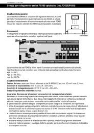
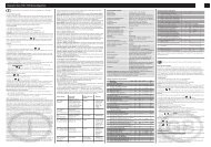
4.2 Power supply selection<br />
The Gateway can be supplied with 3 different voltage values selectable from faston terminals placed on the board:<br />
• 240 Vac 50/60 Hz (default value),<br />
• 120 Vac<br />
• 24 Vac.<br />
The power supply terminals are placed near the transformer and can be recognized through the silk-screen readable on the<br />
printed circuit (see Fig. 4.2.1).<br />
If you decide to change the power supply, be extremely careful when executing this operation and comply with the instructions<br />
here described:<br />
• disconnect the power supply cable;<br />
• remove the cover;<br />
• extract the faston connector with the cable from the supply terminal in use (240Vac);<br />
• take away the faston and the relative protection from the terminal corresponding to the new tension. (e.g. 24 Vac);<br />
• cover the terminal remained uncovered with the faston and related protection.<br />
• replace the fuse present on the Gateway back according to the power supply to be used; for the rated current see<br />
Tab.4.2.1;<br />
• close the cover, earth the casing of the Gateway and reconnect the power.<br />
WARNING: In general the fuse is of the T delayed type, rated voltage 250V, dimensions 5x20mm.<br />
Power supply<br />
240Vac<br />
120Vac<br />
24Vac<br />
Fuse rated current<br />
250mA<br />
250mA<br />
1A<br />
Table 4.2.1<br />
fuse<br />
transformer<br />
power socket<br />
Carel Cod. +030221110 rel. 2.4 del 17/12/02 6