Manuale d'uso
Manuale d'uso
Manuale d'uso

Create successful ePaper yourself
Turn your PDF publications into a flip-book with our unique Google optimized e-Paper software.
Gateway BACnet / BACnet Gateway<br />
<strong>Manuale</strong> d’uso<br />
User manual
Vogliamo farvi risparmiare tempo e denaro!<br />
Vi assicuriamo che la completa lettura di questo manuale vi garantirà una<br />
corretta installazione ed un sicuro utilizzo del prodotto descritto.<br />
We wish to save you time and money!<br />
We can assure you that the thorough reading of this manual will guarantee<br />
correct installation and safe use of the product described
Indice<br />
AVVERTENZE IMPORTANTI 3<br />
1. INTRODUZIONE 5<br />
1.1 Caratteristiche generali 5<br />
2. CONNESSIONI 6<br />
3. INTERFACCIA UTENTE 7<br />
4. INSTALLAZIONE 8<br />
4.1 Suggerimenti per una corretta installazione 8<br />
4.2 Selezione dell’alimentazione 8<br />
5. CONFIGURAZIONE 9<br />
5.1 Utilizzo del software di configurazione 9<br />
5.1.1 Lettura parametri 10<br />
5.1.2 Scrittura parametri 10<br />
6. FUNZIONAMENTO 12<br />
6.1 Generalità sulla comunicazione verso le periferiche Carel 12<br />
6.2 Generalità sul protocollo BACnet 12<br />
6.2.1 Parametri di comunicazione 12<br />
6.2.2 Comandi implementati 13<br />
6.2.3 Database massimo 13<br />
6.2.4 Costruzione di un database BACnet a partire da un database Carel 13<br />
7. CAVI DI CONNESSIONE E IMPOSTAZIONI HARDWARE 16<br />
7.1 Cavi di connessione 16<br />
7.1.1 Cavi di connessione Gateway - periferiche Carel in RS485 16<br />
7.1.2 Cavi di connessione Gateway - periferiche Carel in RS422 16<br />
7.1.3 Cavi di connessione Gateway - terminale di configurazione 17<br />
7.1.4 Cavi di connessione Gateway - computer supervisione in RS232 17<br />
7.2 Ponticelli 17<br />
7.3 Configurazione di fabbrica 18<br />
8. CARATTERISTICHE TECNICHE 19<br />
9. DIMENSIONI MECCANICHE 19<br />
10. APPENDICE: PICS 20
Gateway BACnet<br />
AVVERTENZE IMPORTANTI<br />
PRIMA DI INSTALLARE O INTERVENIRE SULL’APPARECCHIO, LEGGERE ATTENTAMENTE E SEGUIRE<br />
LE ISTRUZIONI CONTENUTE IN QUESTO MANUALE.<br />
Questa apparecchiatura è stata costruita per funzionare senza rischi per gli scopi prefissati purché:<br />
• l’installazione, la conduzione e la manutenzione siano eseguite secondo le istruzioni contenute in questo manuale;<br />
• le condizioni dell’ambiente e della tensione di alimentazione rientrino tra quelle specificate.<br />
Ogni utilizzo diverso da questo e l’apporto di modifiche, non espressamente autorizzate dal costruttore, sono da<br />
intendersi impropri.<br />
La responsabilità di lesioni o danni causati da uso improprio ricadrà esclusivamente sull’utilizzatore.<br />
Si osservi che questa macchina contiene componenti elettrici sotto tensione e quindi tutte le operazioni di servizio o<br />
manutenzione devono essere condotte da personale esperto e qualificato, cosciente delle necessarie precauzioni.<br />
Prima di accedere alle parti interne sezionare la macchina dalla rete elettrica.<br />
Smaltimento delle parti del controllore<br />
Il controllore è composto da parti in metallo e da parti in plastica. Tutte queste parti vanno smaltite secondo le<br />
Normative locali in materia di smaltimento.<br />
Omologazioni: la qualità e la sicurezza dei prodotti Carel sono garantite dal sistema di progettazione e produzione certificato<br />
ISO 9001, nonché dal marchio .<br />
Cod. Carel +030221110 rel. 2.4 del 17/12/02 3
Cod. Carel +030221110 rel. 2.4 del 17/12/02 4<br />
Gateway BACnet
Gateway BACnet<br />
1. INTRODUZIONE<br />
GATEWAYBN0 (di seguito indicato con Gateway) è un dispositivo elettronico Carel che consente l’interfacciamento delle<br />
periferiche Carel con sistemi comunicanti con protocollo standard BACnet, protocollo molto usato e patrimonio ormai di molti<br />
costruttori di BMS.<br />
Il dispositivo esegue automaticamente la traduzione del protocollo di trasmissione Carel nel protocollo di comunicazione<br />
BACnet.<br />
Il traduttore di protocollo è stato realizzato per consentire la connessione di ogni periferica Carel a sistemi BACnet tramite un<br />
gateway standard, senza cioè nessuna necessità di successivi e costosi adattamenti del software.<br />
1.1 Caratteristiche generali<br />
Il protocollo standard BACnet a cui si fa riferimento è quello pubblicato nel documento ufficiale:<br />
ANSI/ASHRAE<br />
Standard 135-1995<br />
Approved by the American National Standards Institute<br />
December 19, 1995<br />
I collegamenti disponibili sul Gateway sono:<br />
• seriale 232 (protocollo PTP) verso la rete BACnet;<br />
• seriale 422 o 485 verso le periferiche Carel;<br />
• seriale 232 per la configurazione del Gateway.<br />
L’alimentazione può essere selezionata tra tre valori: 220 Vac, 120 Vac oppure 24 Vac.<br />
Sono collegabili al Gateway fino a 8 periferiche Carel.<br />
Unitamente al prodotto viene fornito un programma da installare su computer che configura il Gateway in base alle particolari<br />
esigenze dell’applicazione e della rete di periferiche da supervisionare.<br />
Cod. Carel +030221110 rel. 2.4 del 17/12/02 5
Gateway BACnet<br />
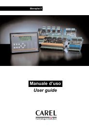
2. CONNESSIONI<br />
I connettori presenti nel pannello posteriore permettono di realizzare le connessioni tra il Gateway, la rete Carel la rete<br />
BACnet.<br />
Fig. 2.1 - Retro del Gateway<br />
modem<br />
Connettore maschio a 9 vie standard. Da utilizzare per connettere il Gateway alla rete BACnet in modalità 232 con protocollo<br />
BACnet PTP (Point-To-Point).<br />
rs422/485<br />
Connettore femmina a 9 vie standard non utilizzato in questo modello di Gateway.<br />
config<br />
Connettore maschio a 9 vie standard, da utilizzare esclusivamente per la configurazione del Gateway. Viene collegato alla<br />
porta seriale 232 del computer su cui va caricato il programma di configurazione.<br />
carel net<br />
Connettore femmina a 9 vie standard, da utilizzare per il collegamento delle periferiche Carel in modalità 422 o 485 con<br />
protocollo proprietario Carel.<br />
relay<br />
Uscita a relè, non utilizzata in questo modello di Gateway.<br />
Cod. Carel +030221110 rel. 2.4 del 17/12/02 6
Gateway BACnet<br />
3. INTERFACCIA UTENTE<br />
Fig. 3.1 - Frontale del Gateway<br />
Tasto print-out<br />
Con il Gateway collegato ad un terminale o ad un computer in emulazione di terminale (tramite il connettore config,<br />
impostazioni: 9600, 8, N, 1), premendo il tasto print-out si visualizza la lista dei parametri di configurazione e la versione del<br />
programma installato nel Gateway stesso.<br />
Tasto reset<br />
Forza il reset del Gateway, avviando la procedura di lettura della configurazione del Gateway stesso e d’interrogazione<br />
completa di tutte le periferiche Carel connesse.<br />
LED line di colore giallo<br />
Indica alimentazione presente.<br />
LED rx e tx di colore verde<br />
Il loro lampeggio continuo segnala una corretta comunicazione tra il Gateway e le periferiche Carel.<br />
LED alarm1 di colore rosso<br />
Se attivato segnala una anomalia nella configurazione iniziale dei parametri.<br />
In tal caso resettare il Gateway. Se il problema persiste è necessario riconfigurare il Gateway con il programma in dotazione<br />
(vedi Procedure per la configurazione iniziale).<br />
LED alarm2 di colore rosso<br />
Se lampeggiante segnala la presenza di anomalie nella comunicazione tra il Gateway e le periferiche Carel.<br />
Probabile causa: incongruenze rispetto a quanto previsto dalla configurazione. Cioè il numero di periferiche riconosciute dal<br />
Gateway è inferiore al numero di periferiche configurate.<br />
AVVERTENZA: il LED lampeggia ad ogni avvio del Gateway, fino a che questo ha acquisito tutte le variabili dalle<br />
periferiche collegate. Prima di tale momento, quindi, il lampeggio del LED è normale e non segnala alcuna anomalia, ma<br />
indica solo che è in corso la procedura di acquisizione delle variabili.<br />
Cod. Carel +030221110 rel. 2.4 del 17/12/02 7
Gateway BACnet<br />
4. INSTALLAZIONE<br />
4.1 Suggerimenti per una corretta installazione<br />
AVVERTENZA. Non lavorare MAI con il Gateway in tensione durante l’installazione e il settaggio hardware.<br />
− Evitare di installare il Gateway in prossimità di cavi di potenza o di sorgenti radiotrasmittenti.<br />
− In fase di manipolazione dei ponticelli interni (vedi Ponticelli), evitare di toccare con le dita i componenti elettronici al fine<br />
di evitare scariche elettrostatiche che potrebbero danneggiare in modo irreparabile i componenti stessi.<br />
− Assicurarsi di aver selezionato la corretta tensione di alimentazione tramite gli appositi connettori faston collocati sulla<br />
scheda elettronica all’interno della scatola metallica del Gateway (vedi Alimentazione).<br />
− Connettere a terra la carcassa del Gateway collegandosi al prigioniero contraddistinto dall’apposita etichetta gialla.<br />
− Prestare particolare attenzione nella corretta realizzazione dei cavi di collegamento.<br />
− Seguire attentamente gli schemi riportati in Cavi di connessione e impostazioni hardware: l’errata connessione di un<br />
solo filo pregiudica il funzionamento di tutto il sistema.<br />
− In fase di configurazione del Gateway seguire scrupolosamente le indicazioni sull’uso del programma relativo.<br />
− Per quanto riguarda la realizzazione di una rete 485 di periferiche Carel:<br />
• utilizzare il cavo indicato in Cavi di connessione Gateway - periferiche Carel.<br />
• SEGUIRE ESATTAMENTE L’INDICAZIONE DELLA POLARITÀ riportata sui morsetti o sulla serigrafia della<br />
scheda degli strumenti;<br />
• fissare la calza o il filo di continuità al morsetto prestando attenzione che LA CALZA NON ENTRI IN<br />
CONTATTO CON LE PARTI METALLICHE DEL QUADRO O CON ALTRI CONDUTTORI. Se la calza è<br />
particolarmente sfilacciata utilizzare della guaina termo-restringente.<br />
• LA CALZA NON DEVE MAI ESSERE MESSA A TERRA, IN NESSUN PUNTO DELLA RETE: gli unici<br />
punti di contatto devono essere i morsetti degli strumenti.<br />
• Il cavo della seriale arriva al morsetto di ogni strumento e riparte verso lo strumento successivo senza effettuare<br />
diramazioni.<br />
• Terminare la rete 485 Carel con una resistenza da 120 Ohm.<br />
4.2 Selezione dell’alimentazione<br />
Il Gateway può essere alimentato con 3 diversi valori di tensione, selezionabili su stampato:<br />
• 240 Vac 50/60 Hz (valore di fabbrica),<br />
• 120 Vac<br />
• 24 Vac.<br />
I morsetti di alimentazione, distinguibili dalla serigrafia leggibile sullo stampato, sono vicini al trasformatore (vedi Fig. 4.2.1).<br />
Se la tensione di alimentazione è diversa da quella impostata dal costruttore procedere con la massima attenzione nell’eseguire<br />
le seguenti operazioni:<br />
• togliere tensione;<br />
• aprire il coperchio;<br />
• estrarre il connettore faston con il cavetto dal morsetto dell’alimentazione predisposta (240 Vac);<br />
• togliere il faston e relativa protezione dal morsetto corrispondente alla nuova tensione (es. 24 Vac);<br />
• coprire con il faston e relativa protezione il morsetto dell’alimentazione predisposta rimasto scoperto;<br />
• connettere il connettore faston con il cavetto al morsetto corrispondente alla nuova tensione;<br />
• sostituire il fusibile sul retro del Gateway a seconda della tensione di alimentazione; per il valore della corrente nominale<br />
fare riferimento alla Tab. 4.2.1;<br />
• chiudere il coperchio, collegare a terra la carcassa del Gateway, e ridare tensione.<br />
N.B. In generale il fusibile è di tipo T ritardato, tensione nominale 250 V, dimensioni 5x20mm.<br />
Alimentazione Corrente nominale<br />
fusibile<br />
240 Vac 250 mA<br />
120 Vac 250 mA<br />
24 Vac 1 A<br />
Tab. 4.2.1<br />
fusibile<br />
trasformatore<br />
ingresso alimentazione<br />
Fig. 4.2.1 - Alimentazione Gateway<br />
Cod. Carel +030221110 rel. 2.4 del 17/12/02 8
Gateway BACnet<br />
5. CONFIGURAZIONE<br />
AVVERTENZA. Per funzionare il Gateway richiede di essere configurato.<br />
La configurazione è resa possibile da un programma fornito unitamente al Gateway da avviare tramite un computer.<br />
Il programma di configurazione del Gateway permette tramite due comandi di leggere o scrivere (rispettivamente) i seguenti<br />
parametri, necessari al corretto funzionamento del dispositivo:<br />
• Numero delle periferiche nella rete Carel<br />
• Baudrate della comunicazione tra il Gateway e la rete BACnet<br />
• Numero di bit (sola lettura) relativo alla comunicazione tra il Gateway e la rete BACnet<br />
• Numero di stop bit (solo lettura) relativo alla comunicazione tra il Gateway e la rete BACnet<br />
• Parità (relativa alla comunicazione tra il Gateway e la rete BACnet)<br />
• Indirizzo in rete BACnet del Gateway<br />
• Offset per l’instance dell’oggetto Device.<br />
5.1 Utilizzo del software di configurazione<br />
Per configurare il Gateway BACnet è necessario un computer, predisposto con seriale 232 e dotato di lettore di floppy disk da 3,5’’.<br />
La seriale 232 del computer va collegata al connettore config sul retro del Gateway con un cavo di tipo null-modem avente un<br />
connettore femmina a 25 o 9 vie standard sul lato computer e femmina a 9 vie standard sul lato Gateway.<br />
Per la piedinatura del cavo seguire lo schema indicato in Cavi di connessione: Gateway - terminale di configurazione.<br />
Nel floppy-disk fornito in dotazione con il Gateway sono contenute 2 versioni del software di installazione.<br />
1) Nei sistemi operativi a 32 bit (Windows95/98,2000,NT,XP) utilizzare solo la versione a 32 bit cioe`:<br />
RDBAC32.EXE per leggere la configurazione del Gateway<br />
WRBAC32.EXE per scrivere la configurazione del Gateway<br />
2) Nel floppy-disk, all’interno della directory “DOS”, e` presente anche la precedente versione a 16 bit da utilizzare solo nel<br />
caso si disponga di un sistema DOS o Windows 3.11.<br />
Gli esempi seguenti si riferiscono al caso 1 cioè di sistema operativo a 32 bit (Windows95 o superiore).<br />
Inserire nel computer il dischetto fornito con il Gateway e digitare sulla linea di comando:<br />
per la lettura dei parametri di configurazione del Gateway:<br />
>a: rdbac32 COM1 <br />
........<br />
>a: rdbac32 COM6 <br />
a seconda della effettiva porta seriale utilizzata (da COM1a COM6).<br />
per la scrittura dei parametri di configurazione del Gateway:<br />
>a: wrbac32 COM1 lista parametri <br />
........<br />
>a: wrbac32 COM6 lista parametri <br />
a seconda della effettiva porta seriale utilizzata (da COM1a COM6).<br />
Per una descrizione dettagliata dei comandi si vedano i paragrafi successivi.<br />
Cod. Carel +030221110 rel. 2.4 del 17/12/02 9
Gateway BACnet<br />
5.1.1 Lettura parametri<br />
Con il comando<br />
rdbac32 PORTA SERIALE<br />
apparirà sullo schermo la configurazione presente nel Gateway e le informazioni relative alla versione del software installata<br />
nel Gateway.<br />
Esempio:<br />
Ad un comando di lettura, un Gateway avente la seguente configurazione:<br />
1 periferica Carel; parametri di funzionamento verso la rete BACnet: 19200 baud, 8 bit dati, 1 stop bit, nessuna parità;<br />
indirizzo BACnet = 3; offset dell’instance dell’oggetto Device = 2;<br />
risponde inviando sullo schermo le seguenti stringhe:<br />
BACNET GATEWAY CONFIGURATION<br />
----------------------------------<br />
VERSION : CAREL/BACNET PTP GATEWAY versione software e data di rilascio<br />
SLAVES : 01<br />
PTP PORT PARAMETER<br />
baud : 19200<br />
bits : 8<br />
stop : 1<br />
parity : NONE<br />
BACNET NETWORK : 3<br />
Device obj Id offset : 002<br />
Se il Gateway non è collegato o non risponde allora apparirà sullo schermo la stringa:<br />
********** ERROR READING GATEWAY CONFIGURATION **********<br />
In questo caso verificare:<br />
• la connessione e la piedinatura del cavo di configurazione (vedi Cavi di connessione),<br />
• l’alimentazione del Gateway (LED giallo acceso).<br />
Se invece appare la scritta: ERROR SERIAL PORT COMx NOT READY<br />
significa che la porta seriale selezionata non e` presente oppure è attualmente utilizzata da un'altra applicazione.<br />
AVVERTENZA: l'utilizzo della porta seriale da parte di applicazioni DOS impegna la linea seriale fino a quando non viene<br />
chiusa la sessione DOS da cui l'applicazione e` stata lanciata.<br />
5.1.2 Scrittura parametri<br />
Usando il comando wrbac32 si possono settare i parametri di funzionamento del Gateway con la seguente sintassi:<br />
wrbac32 porta seriale < numero slave presenti> < parità> < Device<br />
object ID offset ><br />
Digitando soltanto wrbac32 senza parametri o se qualche parametro non viene definito, il programma ripresenta sullo schermo<br />
la corretta sintassi da usare:<br />
wrbac32 <br />
<br />
:COM1..COM2<br />
: 1..8<br />
: 0..6 [300,600,1200,2400,4800,9600,19200]<br />
: 0..4 [NONE,EVEN,ODD,MARK,SPACE]<br />
: 1..65534<br />
: 0..255<br />
Cod. Carel +030221110 rel. 2.4 del 17/12/02 10
Gateway BACnet<br />
AVVERTENZE.<br />
Ogni parametro deve essere separato dal successivo tramite uno spazio.<br />
I parametri da impostare sono:<br />
• n.of.slave: numero di periferiche Carel collegate al Gateway (1÷8); le periferiche devono essere impostate con indirizzi di<br />
rete consecutivi a partire dall’indirizzo 1 e devono essere tutte presenti fino all’indirizzo coincidente con il numero di slave<br />
presenti.<br />
Quindi con numero slave presenti = 5, devono essere in rete le periferiche 1, 2, 3, 4 e 5.<br />
• ptp.baud: baudrate verso la rete BACnet (0=300, 1=600, 2=1200, 3=2400, 4=4800, 5=9600, 6=19200).<br />
• parity: parità verso la rete BACnet (0=NONE, 1=EVEN, 2=ODD, 3=MARK, 4=SPACE).<br />
• bacnet network: indirizzo del Gateway nella rete BACnet (1÷65534).<br />
• Device object Id offset: offset dell’instance dell’oggetto Device. Cioè la periferica Carel avente indirizzo fisico ‘n’ verrà<br />
vista come oggetto Device BACnet avente instance ‘n+offset’. Questo perché l’instance di un oggetto Device dovrebbe<br />
essere unico non solo nella rete in cui si trova ma anche in tutte le reti BACnet collegate. Un offset permette quindi di<br />
spostare gli identificativi dei Device collegati al Gateway in modo da non avere sovrapposizioni.<br />
Lasciare l’offset impostato a 0 se non si vuole usufruire di tale opportunità.<br />
I parametri riguardanti la comunicazione con le periferiche Carel sono fissi (8 bit di parola, nessuna parità, 2 bit di stop e<br />
baudrate=1200 per comunicazione in RS422 o baudrate=19200 per comunicazione in RS85).<br />
ESEMPIO<br />
wrbac32 COM1 8 6 0 3 0<br />
per configurare un Gateway collegato alla COM1 del computer con 8 periferiche Carel, baudrate di 19200 verso la rete<br />
BACnet, nessuna parità e indirizzo BACnet 3 e offset 0.<br />
Se la programmazione va a buon fine sullo schermo apparirà la scritta:<br />
*** GATEWAY PROGRAMMED ***<br />
AVVERTENZA IMPORTANTE. Una volta programmato il Gateway deve essere fatto ripartire (premendo il tasto di<br />
reset o togliendo e ridando alimentazione al Gateway stesso). Solo dopo tale operazione e` possibile leggere le nuove<br />
impostazioni tramite il comando RDBAC32.<br />
Se il Gateway non è collegato o non risponde allora apparirà sullo schermo la stringa:<br />
********** ERROR WRITING GATEWAY CONFIGURATION **********<br />
In questo caso verificare:<br />
• la connessione e la piedinatura del cavo di configurazione (vedi Cavi di connessione),<br />
• l’alimentazione del Gateway (LED giallo acceso),<br />
Cod. Carel +030221110 rel. 2.4 del 17/12/02 11
Gateway BACnet<br />
6. FUNZIONAMENTO<br />
6.1 Generalità sulla comunicazione verso le periferiche Carel<br />
È possibile connettere al Gateway fino a 8 periferiche Carel.<br />
La gestione della comunicazione verso le periferiche Carel avviene secondo una struttura master-slave in polling, ove il master<br />
è costituito dal Gateway e gli slave sono le periferiche Carel. Il protocollo di trasmissione tra Gateway e periferiche è lo<br />
standard privato Carel.<br />
Per ogni periferica sono gestibili fino a:<br />
• 127 variabili analogiche (tra I/O e altre variabili interne del programma)<br />
• 127 variabili intere (tra I/O e altre variabili interne del programma)<br />
• 199 variabili digitali (tra I/O e altre variabili interne del programma)<br />
A richiesta è disponibile il database delle variabili utilizzate da ogni singola periferica Carel. Questo database sarà di<br />
riferimento per chi fornisce il sistema di supervisione, in modo da assegnare l’opportuno significato alle variabili stesse.<br />
Le variabili sono leggibili e/o scrivibili dal supervisore a seconda della periferica collegata e del programma applicativo da<br />
esso utilizzato. Assegnando da supervisore un valore ad una variabile gestibile in sola lettura, il comando verrà accettato dal<br />
Gateway ma non avrà alcun effetto.<br />
Il baudrate di comunicazione verso la rete Carel è il seguente:<br />
Modo di<br />
funzionamento<br />
6.2 Generalità sul protocollo BACnet<br />
Baud rate<br />
rete Carel<br />
RS422 1200<br />
RS485 19200<br />
Tab. 6.1.1<br />
Il Protocollo BACnet implementato nel Gateway Carel è in accordo con quanto descritto nel documento:<br />
ANSI/ASHRAE<br />
Standard 135-1995<br />
Approved by the American National Standards Institute<br />
December 19, 1995<br />
Il protocollo BACnet implementato è di tipo PTP (Point-To-Point) in 232.<br />
Il Gateway è identificabile nella rete BACnet tramite l’assegnazione di un indirizzo. L’indirizzo del Gateway è programmabile<br />
in fase di configurazione (vedi parametro bacnet network in Scrittura parametri).<br />
6.2.1 Parametri di comunicazione<br />
I dati di comunicazione tra rete BACnet e Gateway, sono i seguenti:<br />
Parametro Valori impostabili Significato<br />
baud rate 0<br />
1<br />
2<br />
3<br />
4<br />
5<br />
6<br />
300<br />
600<br />
1200<br />
2400<br />
4800<br />
9600<br />
19200<br />
numero bit 8 (fisso)<br />
numero stop bit<br />
1 (fisso)<br />
parità 0<br />
1<br />
2<br />
3<br />
4<br />
indirizzo 1÷65534<br />
offset 0..255<br />
None<br />
Odd<br />
Even<br />
Mark<br />
Space<br />
Tab. 6.2.1.1<br />
Cod. Carel +030221110 rel. 2.4 del 17/12/02 12
Gateway BACnet<br />
6.2.2 Comandi implementati<br />
Per la descrizione del grado di conformità allo standard BACnet vedi Appendice - PICS al termine del manuale.<br />
I comandi del protocollo BACnet supportati sono ReadProperty, WriteProperty, Who-is e I-Am.<br />
Con queste funzioni è possibile leggere e scrivere un singolo valore alla volta.<br />
I tipi di oggetti supportati sono: Analog Value, Binary Value e Device.<br />
6.2.3 Database massimo<br />
Il massimo numero di variabili trasferibili da una singola periferica Carel al Gateway è il seguente:<br />
Tipo variabile Numero massimo<br />
digitale 199<br />
analogica 127<br />
intera 127<br />
Tab. 6.2.2.1<br />
Il protocollo BACnet non distingue le variabili analogiche dalle intere; le variabili intere Carel vengono accodate alle variabili<br />
analogiche e vengono quindi trasferite al database BACnet con i loro indirizzi sommati all’offset 128 (dec).<br />
Il massimo numero di variabili trasferibili dal Gateway alla rete BACnet è pertanto:<br />
Tipo variabile Numero massimo Corrispondente<br />
oggetto BACnet<br />
digitale 199 binary value<br />
analogica 254 analog value<br />
Tab. 6.2.2.2<br />
AVVERTENZA: le variabili analogiche, intere e digitali con indirizzo 0 non sono gestite dalle periferiche Carel.<br />
Si noti che data la varietà di macchine Carel non si fa distinzione tra variabili d’ingresso (sola lettura) e variabili di uscita<br />
(lettura/scrittura) così che la conoscenza del database e la gestione dello stesso è affidata alla parte presente sul supervisore.<br />
Carel o la casa costruttrice delle unità collegate sarà in grado di fornire le tabelle dei significati delle singole variabili presenti<br />
nei controlli.<br />
6.2.4 Costruzione di un database BACnet a partire da un database Carel<br />
Nel supervisore che fa uso del protocollo BACnet, la gestione del database relativo ad una periferica Carel va fatta tenendo<br />
conto che l’indirizzo di ogni variabile del database deve essere pensato come sequenza di indirizzi:<br />
• indirizzo con cui la rete BACnet vede la sottorete di periferiche Carel (vedi Indirizzo BACnet del Gateway in<br />
Configurazione);<br />
• indirizzo del controllo Carel all’interno della sottorete di periferiche Carel (sommato all’offset dell’instance dell’oggetto<br />
Device “Device obj Id offset” descritto in Configurazione);<br />
• indirizzo della variabile all’interno della periferica Carel (Instance del corrispondente oggetto Analog Value o Binary<br />
Value).<br />
La costruzione di un database implementabile in un supervisore BACnet che gestisca una periferica Carel si effettua poi<br />
tenendo conto che:<br />
• le variabili digitali Carel vengono trasferite con i loro indirizzi al database BACnet<br />
• le variabili analogiche Carel vengono trasferite con i loro indirizzi al database BACnet<br />
• le variabili intere Carel vengono accodate alle variabili analogiche e vengono quindi trasferite al database BACnet con i<br />
loro indirizzi sommati all’offset 128 (dec).<br />
Cod. Carel +030221110 rel. 2.4 del 17/12/02 13
Gateway BACnet<br />
ESEMPI.<br />
ESEMPIO 1: Tabella di corrispondenza tra indirizzo della variabile Carel e indirizzo (instance) in BACnet.<br />
Tipo di variabile Carel Indirizzo Carel Oggetto BACnet BACnet Instance<br />
Digitale 1 binary value 1<br />
Digitale 2 Binary value 2<br />
Digitale .... ... ...<br />
Digitale 198 Binary value 198<br />
Digitale 199 Binary value 199<br />
Analogica 1 Analog value 1<br />
Analogica 2 Analog value 2<br />
Analogica ... ... ...<br />
Analogica 126 Analog value 126<br />
Analogica 127 Analog value 127<br />
Intera 1 Analog value 129<br />
Intera 2 Analog value 130<br />
Intera ... ... ...<br />
Intera 126 Analog value 254<br />
Intera 127 Analog value 255<br />
= 1 + 128<br />
= 127 + 128<br />
ESEMPIO 2: Comando Read Property dell’oggetto Device della periferica Carel connessa al Gateway avente indirizzo fisico<br />
= 1.<br />
Nell’esempio l’offset dell’instance dell’oggetto Device “Device obj Id offset” vale 2 e quindi l’instance dell’oggetto Device in<br />
questione vale 3. L’indirizzo di rete è 1.<br />
= 1 (physical device address) + 2 (Device obj Id offset)<br />
propertyIdentifier<br />
propertyValue<br />
object-identifier<br />
(device,3)<br />
object-name "CAREL DEVICE 00001-01"<br />
object-type<br />
8 (device)<br />
system-status<br />
0 (operational)<br />
physical device address<br />
vendor-name<br />
"CAREL"<br />
vendor-identifier 77<br />
network address<br />
model-name<br />
"CAREL GENERIC DEVICE"<br />
firmware-revision "CAREL/BACNET PTP GATEWAY 1.00 16/10/01"<br />
application-software "GENERIC S/W VERSION"<br />
protocol-version 1<br />
protocol-conformance-class 2<br />
protocol-services<br />
(FALSE,FALSE,FALSE,FALSE,FALSE,FALSE,FALSE,FALSE,FAL<br />
SE,FALSE,FALSE,FALSE,TRUE,FALSE,FALSE,TRUE,FALSE,FAL<br />
SE,FALSE,FALSE,FALSE,FALSE,FALSE,FALSE,FALSE,FALSE,T<br />
RUE,FALSE,FALSE,FALSE,FALSE,FALSE,FALSE,FALSE,TRUE)<br />
protocol-object-types (FALSE,FALSE,TRUE,FALSE,FALSE,TRUE,FALSE,FALSE,TRUE,<br />
FALSE,FALSE,FALSE,FALSE,FALSE,FALSE,FALSE,FALSE,FALS<br />
E)<br />
object-list[0] 455<br />
object-list[1]<br />
(device,3)<br />
object-list[2]<br />
(Analog -value,1)<br />
... ...<br />
max-apdu-length-accepted 206<br />
segmentation-supported 3 (no-segmentation)<br />
apdu-timout 3000<br />
number-of-apdu-retries 3<br />
device-address-binding <br />
Cod. Carel +030221110 rel. 2.4 del 17/12/02 14
Gateway BACnet<br />
ESEMPIO 3: Comando Read Property dell’oggetto Analog Value con instance 4 della periferica Carel connessa al Gateway<br />
dell’esempio precedente.<br />
variable instance<br />
propertyIdentifier<br />
propertyValue<br />
object-identifier<br />
(Analog -value,4)<br />
object-name "CAREL ANALOG 00001-01-004"<br />
object-type<br />
2(Analog -value)<br />
physical device address<br />
present-value 0<br />
status-flags<br />
(FALSE,FALSE,FALSE,FALSE)<br />
network address<br />
event-state<br />
0(normal)<br />
out-of-service<br />
FALSE<br />
units<br />
95 (no-units)<br />
ESEMPIO 4: Comando Read Property dell’oggetto Binary Value con instance 4 della periferica Carel connessa al Gateway<br />
dell’esempio precedente:<br />
propertyIdentifier<br />
propertyValue<br />
variable instance<br />
object-identifier<br />
(Binary-value,4)<br />
object-name "CAREL BOOL 00001-01-004"<br />
object-type<br />
5(Binary-value)<br />
physical device address<br />
present-value<br />
0(inactive)<br />
status-flags<br />
(FALSE,FALSE,FALSE,FALSE) network address<br />
event-state<br />
0 (normal)<br />
out-of-service<br />
FALSE<br />
Cod. Carel +030221110 rel. 2.4 del 17/12/02 15
Gateway BACnet<br />
7. CAVI DI CONNESSIONE E IMPOSTAZIONI HARDWARE<br />
7.1 Cavi di connessione<br />
7.1.1 Cavi di connessione Gateway - periferiche Carel in RS485<br />
Il cavo di connessione del Gateway con le periferiche Carel (connettore Carel Net) in RS485 che Carel consiglia è:<br />
• a 2 fili ritorti,<br />
• schermato, preferibilmente con filo di continuità,<br />
• di sezione AWG20 (0,5 mm 2 ) o AWG22 (0,32÷0,38 mm 2 ),<br />
• capacità tra i conduttori minore di 100 pF/m<br />
(i modelli 8761 e 8762 della Belden, ad esempio, soddisfano i precedenti requisiti)<br />
• con la seguente piedinatura:<br />
Gateway (conn. Carel Net)<br />
1<br />
2<br />
3<br />
4<br />
5<br />
Gnd<br />
maschio 9 poli<br />
Tx/rx+<br />
Tx/rx -<br />
Rete Carel<br />
G + - G + -<br />
....<br />
120 Ohm<br />
Fig. 7.1.1.1 - Connessione in 485<br />
7.1.2 Cavi di connessione Gateway - periferiche Carel in RS422<br />
Il cavo di connessione del Gateway con le periferiche Carel (connettore Carel Net) in RS422 che Carel consiglia (cod.<br />
98C136C004) è:<br />
• a 6 fili,<br />
• schermato, preferibilmente con filo di continuità,<br />
• di sezione AWG24.<br />
• con la seguente piedinatura:<br />
Gateway (conn. Carel Net)<br />
1 gnd<br />
6 2 rx+<br />
7 3 rx-<br />
4 tx+<br />
5 tx-<br />
maschio 9 poli<br />
Box deriv. periferica (cod. 98C145C034)<br />
gnd 1<br />
tx+ 2<br />
tx- 3<br />
rx+ 4<br />
rx- 5<br />
femmina 9 poli<br />
Fig. 7.1.2.1 - Connessione in 422<br />
AVVERTENZA. Prestare attenzione ai piedini 6 e 7 del connettore lato Gateway. Devono essere cortocircuitati come<br />
indicato in figura: 6 cortocircuitato con 2; 7 cortocircuitato con 3.<br />
Cod. Carel +030221110 rel. 2.4 del 17/12/02 16
Gateway BACnet<br />
7.1.3 Cavi di connessione Gateway - terminale di configurazione<br />
Questo cavo standard (null-modem) permette la connessione del Gateway (connettore config) a un terminale o computer per<br />
consentirne la configurazione iniziale tramite il programma nel dischetto in dotazione. A configurazione ultimata il cavo va<br />
rimosso.<br />
Computer<br />
2<br />
3<br />
7<br />
tx<br />
rx<br />
gnd<br />
Gateway (conn. config.)<br />
rx<br />
tx<br />
gnd<br />
2<br />
3<br />
5<br />
Computer<br />
3<br />
2<br />
5<br />
tx<br />
rx<br />
gnd<br />
Gateway (conn. config.)<br />
rx<br />
tx<br />
gnd<br />
2<br />
3<br />
5<br />
femmina 25 poli<br />
femmina 9 poli<br />
oppure<br />
femmina 9 poli<br />
femmina 9 poli<br />
Fig. 7.1.3.1<br />
7.1.4 Cavi di connessione Gateway - computer supervisione in RS232<br />
Il cavo di collegamento tra Gateway (collegato al connettore modem) e computer di supervisione è un cavo standard nullmodem.<br />
Gli schemi per la connessione in RS232 sono gli stessi della connessione Cavi di connessione Gateway - terminale<br />
di configurazione riportati nella figura precedente.<br />
Computer<br />
2<br />
3<br />
7<br />
tx<br />
rx<br />
gnd<br />
Gateway (conn. modem)<br />
rx<br />
tx<br />
gnd<br />
2<br />
3<br />
5<br />
Computer<br />
3<br />
2<br />
5<br />
tx<br />
rx<br />
gnd<br />
Gateway (conn. modem)<br />
rx<br />
tx<br />
gnd<br />
2<br />
3<br />
5<br />
femmina 25 poli<br />
femmina 9 poli<br />
oppure<br />
femmina 9 poli<br />
femmina 9 poli<br />
Fig. 7.1.4.1<br />
Fare comunque riferimento alle specifiche del computer di supervisione per eventuali altri tipi di collegamento.<br />
Il Gateway in ogni caso gestisce solo i segnali tx e rx.<br />
7.2 Ponticelli<br />
Aprendo il coperchio del Gateway (seguire le avvertenze descritte in Installazione) si accede ai quattro ponticelli di selezione<br />
presenti sulla scheda, indicati con A, B, C, D, il cui significato è riportato nella tabella seguente.<br />
Fig. 7.2.1<br />
Cod. Carel +030221110 rel. 2.4 del 17/12/02 17
Gateway BACnet<br />
Il significato dei ponticelli A, B, C, D riportati in Fig. 7.2.1 è il seguente:<br />
Ponticelli Descrizione Configurazione di fabbrica<br />
A in posizione 1-2 abilitazione della porta seriale 232 verso il supervisore X<br />
A in posizione 2-3 non gestito<br />
B in posizione 1-2 non gestito<br />
B in posizione 2-3 non gestito<br />
C in posizione 1-2 abilita la comunicazione verso la rete di strumenti Carel in<br />
X<br />
modalità 485 (in uscita dalla porta carel net)<br />
C in posizione 2-3 abilita la comunicazione verso la rete di strumenti Carel in<br />
modalità 422 (in uscita dalla porta carel net)<br />
D in posizione NO non gestito<br />
D in posizione NC non gestito<br />
Tab. 7.2.1<br />
Riassumendo solo il ponticello C può essere impostato nel seguente modo:<br />
Ponticello lato Carel in 485 lato Carel in 422<br />
C 1-2 2-3<br />
Tab. 7.2.2<br />
7.3 Configurazione di fabbrica<br />
La configurazione di fabbrica prevede collegamenti in:<br />
232 verso il computer per la configurazione,<br />
232 verso rete/sistema di supervisione BACnet,<br />
485 verso la rete Carel<br />
Alimentazione 240 Vac<br />
Cod. Carel +030221110 rel. 2.4 del 17/12/02 18
Gateway BACnet<br />
8. CARATTERISTICHE TECNICHE<br />
Alimentazione<br />
Le alimentazioni previste (selezionabili da morsetti faston all’interno della scatola) sono:<br />
240 Vac (+10%, -15%) standard di fabbrica<br />
120 Vac (+10%, -15%)<br />
24 Vac (+10%, -15%)<br />
Potenza<br />
5 VA<br />
Temperature di utilizzo 0 ÷ 60 ºC<br />
Temperatura d’immagazzinamento -10 ÷ 70 ºC<br />
Umidità di utilizzo<br />
0 ÷ 80%RH non condensante<br />
Umidità d’immagazzinamento 0 ÷ 80%RH non condensante<br />
Microprocessore<br />
Intel 8032 a 12 MHz<br />
Programma<br />
residente in eprom da 64KB.<br />
Configurazione hardware<br />
La configurazione di default prevede i seguenti collegamenti:<br />
RS232 verso il computer per la configurazione<br />
RS232 verso il computer di supervisione BACnet (ponticello A in 1-2)<br />
RS485 verso la rete di periferiche Carel (ponticello C in 1-2)<br />
Protocollo lato periferiche RS422 con protocollo di comunicazione proprietario Carel, baudrate 1200<br />
RS485 con protocollo di comunicazione proprietario Carel, baudrate 19200<br />
Protocollo lato supervisore<br />
RS232 con protocollo di comunicazione BACnet PTP<br />
Tab. 8.1<br />
9. DIMENSIONI MECCANICHE<br />
Di seguito vengono messe in evidenza le dimensioni della carpenteria del Gateway (mm)<br />
Vista frontale<br />
Vista dall’alto<br />
Fig. 8.1.1<br />
Carel si riserva la possibilità di apportare modifiche o cambiamenti ai propri prodotti senza alcun preavviso.<br />
Cod. Carel +030221110 rel. 2.4 del 17/12/02 19
10. APPENDICE: PICS<br />
BACnet PROTOCOL IMPLEMENTATION CONFORMANCE STATEMENT<br />
Gateway BACnet<br />
Date: 28/06/02<br />
Vendor Name: CAREL<br />
Product Name: GATEWAY BACnet<br />
Product Model Number: GATEWAYBN0<br />
Application Software Version: GENERIC S/W VERSION<br />
Firmware Revision: CAREL/BACNET PTP GATEWAY 1.00 28/06/02 BACnet Protocol Revision: 1<br />
Product Description:<br />
GATEWAYBN0 is a Carel electronic device that allows to interface Carel controllers with systems communicating with the BACnet Point-<br />
To-Point protocol. The device makes automatically the translation of the Carel transmission protocol (electrical standard EIA 422 or EIA<br />
485) into the BACnet one (electrical standard EIA 232).<br />
BACnet Standardized Device Profile (Annex L):<br />
! BACnet Operator Workstation (B-OWS)<br />
! BACnet Building Controller (B-BC)<br />
! BACnet Advanced Application Controller (B-AAC)<br />
! BACnet Application Specific Controller (B-ASC)<br />
! BACnet Smart Sensor (B-SS)<br />
" BACnet Smart Actuator (B-SA)<br />
List all BACnet Interoperability Building Blocks Supported (Annex K): DS-RP-B, DS-WP-B, DM-DDB-B<br />
Segmentation Capability:<br />
! Segmented requests supported Window Size: ____________<br />
! Segmented responses supported Window Size: ____________<br />
Standard Object Types Supported:<br />
Object Type<br />
Dynamically<br />
Creatable<br />
Dynamically<br />
Deleteable<br />
Optional<br />
Properties<br />
Supported<br />
Writable<br />
Properties<br />
Proprietary<br />
Properties<br />
Analog Value NO NO - Present Value -<br />
Binary Value NO NO - Present Value -<br />
Device NO NO - - -<br />
Property Range Restrictions: Maximum APDU size in octets : 206<br />
Data Link Layer Option:<br />
! BACnet IP, (Annex J)<br />
! BACnet IP, (Annex J), Foreign Device<br />
! ISO 8802-3, Ethernet (Clause 7)<br />
! ANSI/ATA 878.1, 2.5 Mb. ARCNET (Clause 8)<br />
! ANSI/ATA 878.1, RS-485 ARCNET (Clause 8), baud rate(s) ____________<br />
! MS/TP master (Clause 9), baud rate(s):<br />
! MS/TP slave (Clause 9), baud rate(s):<br />
" Point-To-Point, EIA 232 (Clause 10), baud rate(s): 300, 600, 1200, 2400, 4800, 9600, 19200<br />
! Point-To-Point, modem, (Clause 10), baud rate(s):<br />
! LonTalk, (Clause 11), medium: __________<br />
! Other: __________<br />
Device Address Binding:<br />
Is static device binding supported ! Yes " No<br />
Networking Options:<br />
! Router, Clause 6<br />
! Annex H, BACnet Tunneling Router over IP<br />
! BACnet/IP Broadcast Management Device (BBMD)<br />
Does the BBMD support registrations by Foreign Devices ! Yes ! No<br />
Character Sets Supported:<br />
Indicated support for multiple character sets does not imply that they can all be supported simultaneously.<br />
" ANSI X3.4 ! IBM/Microsoft DBCS ! ISO 8859-1<br />
! ISO 10646 (UCS-2) ! ISO 10646 (ICS-4) ! JIS C 6226<br />
Types of non-BACnet equipment/network(s) that the gateway supports:<br />
Carel proprietary network, standard EIA 485 or EIA 422<br />
Cod. Carel +030221110 rel. 2.4 del 17/12/02 20
Contents<br />
1. INTRODUCTION 3<br />
1.1 General description 3<br />
2. CONNECTIONS 4<br />
3. USER INTERFACE 5<br />
4. INSTALLATION 6<br />
4.1 Suggestions for a correct installation 6<br />
4.2 Power supply selection 6<br />
5. CONFIGURATION 7<br />
5.1 Use of the configuration software 7<br />
5.1.1 Parameter reading 8<br />
5.1.2 Parameter writing 8<br />
6 OPERATION 10<br />
6.1 General information on the communication towards Carel peripherals 10<br />
6.2 General information on the BACnet protocol 10<br />
6.2.1 Communication parameters 10<br />
6.2.2 Implemented commands 11<br />
6.2.3 Maximum database 11<br />
6.2.4 Construction of a BACnet database starting from a Carel database 11<br />
7 CONNECTION CABLES AND HARDWARE SETTINGS 14<br />
7.1 Connection cables 14<br />
7.1.1 Gateway connection cables- Carel peripherals in RS485 line 14<br />
7.1.2 Gateway connection cables- Carel peripherals in RS422 line 14<br />
7.1.3 Gateway connection cables - configuration terminal 15<br />
7.1.4 Gateway connection cables - supervisory computer in RS232 15<br />
7.2 Jumpers 15<br />
7.3 Default configuration 16<br />
8. TECHNICAL SPECIFICATIONS 17<br />
9. MECHANICAL DIMENSIONS 17<br />
10. APPENDIX - PICS 18
Gateway BACnet<br />
IMPORTANT WARNINGS<br />
BEFORE INSTALLING OR OPERATING ON THE DEVICE, CAREFULLY READ THE INSTRUCTIONS IN THIS<br />
MANUAL.<br />
This instrument has been designed to operate without risks only if:<br />
• Installation, operation and maintenance are performed according to the instructions of this manual;<br />
• Environmental conditions and supply voltage fall within the values indicated here below;<br />
Any different use or changes which have not been previously authorised by the manufacturer, are considered improper.<br />
Responsibility for injures or damage caused by improper use will fall exclusively on the user.<br />
Warning: voltage is present in some electrical components of this instrument, thus all the service or maintenance<br />
operations must be performed by expert and skilled personnel only, aware of the necessary precautions to be taken.<br />
Before accessing the internal parts, disconnect the power supply.<br />
Disposal of the instrument:<br />
The controller is made up of metal and plastic parts. All these components must be disposed of according to the standards<br />
in force in your own country.<br />
Certification: the quality and safety of Carel products are guaranteed by Carel's ISO 9001 certified design and production<br />
system, as well as the<br />
mark.<br />
Carel Cod. +030221110 rel. 2.4 del 17/12/02 3
Carel Cod. +030221110 rel. 2.4 del 17/12/02 4<br />
Gateway BACnet
BACnet Gateway<br />
1. INTRODUCTION<br />
GATEWAYBN0 (hereby called “Gateway”) is a Carel electronic device that allows to interface Carel-controllers (maximum<br />
number: 8) with systems communicating with the BACnet. This is a frequently used protocol and a property of many BMS<br />
manufacturers. The device makes automatically the translation of the Carel transmission protocol into the communication<br />
protocol BACnet.<br />
The protocol translator has been created to allow the connection of each Carel peripheral to BACnet systems using a<br />
standard gateway, i.e. without the need of following and expensive software adaptations.<br />
1.1 General description<br />
The reference BACnet protocol is the one defined by the official document:<br />
ANSI/ASHRAE<br />
Standard 135-1995<br />
Approved by the American National Standards Institute<br />
December 19, 1995<br />
The connections available on the Gateway are:<br />
• serial 232 (protocol PTP) towards the BACnet;<br />
• serial 422 or 485 towards Carel peripherals;<br />
• serial 232 for the Gateway configuration.<br />
The power supply can be selected among the following three values: 220Vac, 120Vac or 24Vac.<br />
Up to 8 Carel peripherals can be connected to the Gateway.<br />
A program is supplied together with the product to configure the Gateway according to the particular requirements of the<br />
application and peripheral network to be supervisioned.<br />
Carel Cod. +030221110 rel. 2.4 del 17/12/02 3
BACnet Gateway<br />
2. CONNECTIONS<br />
The connectors, which are placed on the back panel, allow the achievement of the connections between the Gateway, the<br />
Carel network and the BACnet.<br />
Fig. 2.1 - Gateway back<br />
modem<br />
Standard 9-poles male connector. It has to be used to connect the Gateway to the BACnet in 232 mode with protocol BACnet<br />
BACnet PTP (Point-To-Point).<br />
rs422/485<br />
Standard 9-poles female connector not used in this Gateway model.<br />
config<br />
Standard 9-poles male connector. It has to be used only for the Gateway configuration. It is connected to the serial port 232 of<br />
the PC to which is downloaded the configuration program.<br />
carel net<br />
Standard 9-poles female connector. It has to be used for the connection of the Carel peripherals in 422 or 485 modes with<br />
Carel owner protocol.<br />
relay<br />
Relay output not to be used in this Gateway model.<br />
Carel Cod. +030221110 rel. 2.4 del 17/12/02 4
BACnet Gateway<br />
3. USER INTERFACE<br />
Fig. 3.1 - Gateway front<br />
Print-out button<br />
If Gateway is connected to a terminal or a PC in terminal emulation (through the config connector - selections: 9600, 8, N, 1),<br />
the print-out button displays the configuration-parameter list and the program version installed in the Gateway EPROM.<br />
Reset button<br />
Forces the Gateway reset, starting the reading procedure of the Gateway configuration and the complete inquiry procedure of<br />
all the connected peripherals.<br />
LED line (yellow)<br />
It shows the power supply.<br />
rx and tx LEDs (green)<br />
Their persistent blinking signals a correct communication between the Gateway and the Carel peripherals.<br />
alarm1 LED (red)<br />
If activated, it signals an anomaly in the parameter initial configuration.<br />
In this case, reset the Gateway. If the problem persists, it is necessary to riconfigure the Gateway with the issued program (see<br />
Procedures for the starting configuration).<br />
alarm2 LED (red)<br />
If blinking, it signals an error in the communication between the Gateway and one or more Carel peripherals.<br />
The cause may reside in inconsistencies compared to what was envisaged by the configuration. That is to say the number of<br />
the peripherals recognized from the Gateway is lower than the number of the configurated peripherals.<br />
WARNING: the LED flashes at every start-up of the Gateway, as long as it acquires all the variables from the connected<br />
peripherals. Therefore, before this the LED flashing is normal and doesn’t signal any anomaly, but it only indicates that the<br />
variable acquisition procedure is in progress.<br />
Carel Cod. +030221110 rel. 2.4 del 17/12/02 5
BACnet Gateway<br />
4. INSTALLATION<br />
4.1 Suggestions for a correct installation<br />
WARNING: be sure that the Gateway is turned off during the installation and the hardware setting.<br />
− Do not install the Gateway near to power cables or radiobroadcasting sources.<br />
− When handling the internal jumper (see Jumpers), do not touch with bare hands the electronical components to avoid<br />
electrostatic discharges that could damage irreparably the components themselves.<br />
− Be sure to have selected the right power supply voltage using the proper faston connectors placed on the electronic board<br />
within the metallic case of the Gateway (see Power Supply).<br />
− Connect to earth the Gateway casing connecting to the stud characterised by the proper yellow label.<br />
− Pay attention to the correct creation of the connection cables.<br />
− Follow with care the instructions of the diagrams in Connection cables and hardware settings: the incorrect connection of<br />
only one wire compromise the operation of the entire system.<br />
− During the Gateway configuration phase, follow scrupulously the indications on the use of the connected program.<br />
− For what concerns the creation of a 485 Carel peripheral net:<br />
• use the cable suggested in Gateway connection cables - Carel peripherals.<br />
• FOLLOW EXACTLY THE INDICATION OF THE POLARITY reproduced on the terminals or on the silk-screen<br />
of the board of the instruments;<br />
• fix the shield or the continuity wire to the terminal paying attention that the SHIELD MUST NOT GET IN<br />
TOUCH WITH THE METALLIC PARTS OF THE PANEL OR WITH OTHER WIRES. If the shield is particularly<br />
broken, use some thermoshrinking sheath.<br />
• THE SHIELD MUST NOT BE EARTH CONNECTED, NOWHERE IN THE NET: the only contacts must be the<br />
terminals of the instruments.<br />
• The serial cable reaches the terminal of each instrument and goes back to the following instrument without<br />
branches.<br />
• End the 485 net with a 120Ohm resistor.<br />
4.2 Power supply selection<br />
The Gateway can be supplied with 3 different voltage values selectable from faston terminals placed on the board:<br />
• 240 Vac 50/60 Hz (default value),<br />
• 120 Vac<br />
• 24 Vac.<br />
The power supply terminals are placed near the transformer and can be recognized through the silk-screen readable on the<br />
printed circuit (see Fig. 4.2.1).<br />
If you decide to change the power supply, be extremely careful when executing this operation and comply with the instructions<br />
here described:<br />
• disconnect the power supply cable;<br />
• remove the cover;<br />
• extract the faston connector with the cable from the supply terminal in use (240Vac);<br />
• take away the faston and the relative protection from the terminal corresponding to the new tension. (e.g. 24 Vac);<br />
• cover the terminal remained uncovered with the faston and related protection.<br />
• replace the fuse present on the Gateway back according to the power supply to be used; for the rated current see<br />
Tab.4.2.1;<br />
• close the cover, earth the casing of the Gateway and reconnect the power.<br />
WARNING: In general the fuse is of the T delayed type, rated voltage 250V, dimensions 5x20mm.<br />
Power supply<br />
240Vac<br />
120Vac<br />
24Vac<br />
Fuse rated current<br />
250mA<br />
250mA<br />
1A<br />
Table 4.2.1<br />
fuse<br />
transformer<br />
power socket<br />
Carel Cod. +030221110 rel. 2.4 del 17/12/02 6
BACnet Gateway<br />
5. CONFIGURATION<br />
WARNING. In order to work, the Gateway must be configured.<br />
The configuration is allowed by a program - supplied together with the Gateway - that has to be start-up using a computer.<br />
Using two commands, the Gateway configuration program allows the reading or writing (respectively) of the following<br />
parameters, which are necessary for the correct operationof the device:<br />
• Number of the peripherals in the Carel net.<br />
• Communication baudrate between the Gateway and the BACnet.<br />
• Number of bits (only reading) related to the comuunication between the Gateway and the BACne.t<br />
• Number of stop bits (only reading) related to the comuunication between the Gateway and the BACnet.<br />
• Parity (related to the comuunication the Gateway and the BACnet).<br />
• BACnet address of the Gateway.<br />
• Offset for the Device instance.<br />
5.1 Use of the configuration software<br />
To configure the GatewayBN0 it is needed a PC with serial RS232 and supplied with floppy disk 3,5’’ reader.<br />
The serial 232 of the computer must be connected to the connector config on the back of the Gateway using a null-modem<br />
cable that has a standard female connector with 25 or 9 ways on the computer side and a standard female connector with 9<br />
ways on the Gateway side.<br />
For the pin-out of the cable, follow the diagram indicated in Connection cables: Gateway - configuration terminal (see pg. 37).<br />
The floppy disk, which is supplied with the Gateway, contains 2 versions of the setup software:<br />
1) In the 32 bit operating systems (Windows 95/98, NT, 2000, XP) use only the 32-bit version i.e.:<br />
RDBAC32.EXE to read the current Gatewat setup<br />
WRBAC32.EXE to write a new configuration on the gateway<br />
2) In the DOS directory of the same floppy disk there's also the 16 bit version to use only in DOS or Windows 3.11 systems<br />
The following examples refers only to the point 1, that is 32 bit operating system (Windows 95 or higher).<br />
Insert the floppy disk, which is supplied with the Gateway, in the computer and type on the command line:<br />
for the reading of the Gateway configuration parameters:<br />
>a:rdbac32 COM1 <br />
........<br />
>a: rdbac32 COM6 <br />
depending on the use of the COM1 ... COM6 serials respectively.<br />
for the writing of the Gateway configuration parameters:<br />
>a: wrbac32 COM1 parameter list <br />
........<br />
>a: wrbac32 COM6 parameter list <br />
depending on the use of the COM1 ... COM6 serials respectively.<br />
For a detailed description of the commands see the following paragraphs.<br />
Carel Cod. +030221110 rel. 2.4 del 17/12/02 7
BACnet Gateway<br />
5.1.1 Parameter reading<br />
With the command<br />
rdbac32 SERIAL PORT<br />
on the display, the current Gateway configuration and the information connected to the software version installed in the<br />
Gateway will be displayed.<br />
Example:<br />
With the reading command, a Gateway having the following configuration:<br />
1 Carel peripheral; operation parameters towards the BACnet: 19200 baud, 8 bit data, 1 stop bit, no parity; BACnet<br />
address = 3; instance offset of the Device Object = 2;<br />
it answers with the following strings on the display :<br />
BACNET GATEWAY CONFIGURATION<br />
----------------------------------<br />
VERSION : CAREL/BACNET PTP GATEWAY software version and release date<br />
SLAVES : 01<br />
PTP PORT PARAMETER<br />
baud : 19200<br />
bits : 8<br />
stop : 1<br />
parity : NONE<br />
BACNET NETWORK : 3<br />
Device obj Id offset : 002<br />
If the Gateway is not connected or does not answer, the following string will be displayed on the screen:<br />
********** ERROR READING GATEWAY CONFIGURATION **********<br />
In this case verify:<br />
• the connection and the pi-out of the configuration cable (see Connection cables)<br />
• the Gateway power supply (yellow LED ON)<br />
If the following string is displayed: ERROR SERIAL PORT COMx NOT READY<br />
it means that the selected serial port is not present or it is being used by another application.<br />
WARNING: the usage of the serial port by some DOS applications occupies the serial line till the DOS session where the<br />
application has been run from is closed.<br />
5.1.2 Parameter writing<br />
Using the command wrbac32 it is possible to set the Gateway operating parameters with the following syntax:<br />
wrbac32 serial port < present slave number > < parity> < Gateway BACnet address > < Device<br />
object ID offset ><br />
Keystroking only wrbac32 without parameters or if some parameter is not defined, the program displays on the display the<br />
right syntax to be used:<br />
wrbac32 <br />
<br />
:COM1..COM2<br />
: 1..8<br />
: 0..6 [300,600,1200,2400,4800,9600,19200]<br />
: 0..4 [NONE,EVEN,ODD,MARK,SPACE]<br />
: 1..65534<br />
: 0..255<br />
Carel Cod. +030221110 rel. 2.4 del 17/12/02 8
BACnet Gateway<br />
WARNING.<br />
Each parameter must be separated from the next through a blank.<br />
The parameters to be set are:<br />
• n.of.slave: number of Carel peripherals connected to the Gateway (1÷8); the peripherals must be set with consecutive net<br />
addresses starting from address 1 and must be all present up to the address that coincides with the number of the present<br />
slaves.<br />
Therefore with 5 slaves, the peripherals 1, 2, 3, 4 and 5 must be connected to the net.<br />
• ptp.baud: baudrate towards the BACnet (0=300, 1=600, 2=1200, 3=2400, 4=4800, 5=9600, 6=19200).<br />
• parity: parity towards the BACnet (0=NONE, 1=EVEN, 2=ODD, 3=MARK, 4=SPACE).<br />
• bacnet network: the Gateway address in the BACnet (1÷65534).<br />
• Device object Id offset: offset of the Device object instance. That is to say, Carel’s peripheral, whose address is ‘n’, will be<br />
seen as BACnet Device Object having instance ‘n+offset’. This is why the instance of a Device object should be unique,<br />
not only in the network in which it is placed, but also in all the connected BACnet networks. An offset allows moving the<br />
Ids of the Device connected to the Gateway so as not to cause any overlapping.<br />
Let the offset set at 0, if you don’t want to make use of this opportunity.<br />
Parameters relating to the communication towards Carel peripherals are fixed (8 bit data, no parity, 2 stop bit,<br />
baudrate=1200 for RS422 communication and baudrate=19200 for RS485 communication)<br />
EXAMPLE<br />
wrbac32 COM1 8 6 0 3 0<br />
to configurate a Gateway connected to the COM1 of the computer with 8 Carel peripherals, 19200 baudrate towards the<br />
BACnet, no parity and address BACnet 3 e offset 0.<br />
If the programming is effective, the PC monitor will display the string:<br />
*** GATEWAY PROGRAMMED***<br />
IMPORTANT WARNING. Once programmed, the Gateway must be start-up again (pressing the reset button or turning off<br />
and then on the Gateway itself). Only after this it will be possible reading the new settings using the RDBAC32 command.<br />
If the Gateway is not connected or does not answer, the following string will be displayed on the screen:<br />
” ********** ERROR WRITING GATEWAY CONFIGURATION ********** ”<br />
In this case check:<br />
• the connection and the pin-out of the configuration cable (see Connection cables),<br />
• the Gateway power supply (yellow LED ON).<br />
Carel Cod. +030221110 rel. 2.4 del 17/12/02 9
BACnet Gateway<br />
6 OPERATION<br />
6.1 General information on the communication towards Carel peripherals<br />
It’s possible to connect to the Gateway up to 8 Carel peripherals.<br />
The communication management towards Carel peripherals takes place according to a master-slave structure in polling,<br />
where the Gateway is the master and the Carel peripherals are the slaves.<br />
For each peripheral, it is possible to manage up to:<br />
• 127 analog variables (between I/O and other internal variables of the program);<br />
• 127 integer variables (between I/O and other internal variables of the program);<br />
• 199 digital variables (between I/O and other internal variables of the program).<br />
On request, the database of variables utilized by each single Carel controller is available. This will be a reference to whom<br />
provides the supervisory system so as to assign the suitable meaning to the variables themselves. The variables can be read<br />
and/or written from the supervisory system according to the instrument connected and/or application program installed. By<br />
assigning from supervisor a value to a reading only variable, the command will be accepted by the Gateway but it will not be<br />
effective at all.<br />
The communication baud-rate to the Carel network is:<br />
Working Way Carel Network Baud rate<br />
RS422 1200<br />
RS485 19200<br />
Table 6.1.1<br />
6.2 General information on the BACnet protocol<br />
The BACnet protocol implemented in the Carel Gateway complies with what is described in the following document:<br />
ANSI/ASHRAE<br />
Standard 135-1995<br />
Approved by the American National Standards Institute<br />
December 19, 1995<br />
The implemeted BACnet protocol is a PTP type (Point-To-Point) in 232.<br />
The Gateway can be identified in the BACnet thanks to the assignment of an address. The Gateway address can be<br />
programmed during the configuration phase (see parameter bacnet network in Parameter writing).<br />
6.2.1 Communication parameters<br />
The communication parameters between BACnet and Gateway are the following:<br />
Parameter Selectable values Meaning<br />
baud rate 0<br />
1<br />
2<br />
3<br />
4<br />
5<br />
6<br />
300<br />
600<br />
1200<br />
2400<br />
4800<br />
9600<br />
19200<br />
bit number<br />
8 (fixed)<br />
stop bit number<br />
1 (fixed)<br />
parity 0<br />
1<br />
2<br />
3<br />
4<br />
network address 1÷65534<br />
offset 0..255<br />
None<br />
Odd<br />
Even<br />
Mark<br />
Space<br />
Tab. 6.2.1.1<br />
Carel Cod. +030221110 rel. 2.4 del 17/12/02 10
BACnet Gateway<br />
6.2.2 Implemented commands<br />
For the description of BACnet capabilities supported by the Gateway refer to Appendix - PICS at the end of this manual.<br />
The commands of the BACnet protocol implemented are ReadProperty, WriteProperty, Who-is and I-Am.<br />
With this functions it is possible to read and write a single value at a time.<br />
The object types supported are: Analog Value, Binary Value and Device.<br />
6.2.3 Maximum database<br />
The maximum number of variables which can be transferred from a Carel peripheral to the Gateway is the following:<br />
Variable type<br />
Max. number<br />
digital 199<br />
analog 127<br />
integer 127<br />
Table 6.2.2.1<br />
The BACnet protocol does not distinguish between analog and integer variables; the Carel integer variables are tailored to<br />
the analog variables and are then transferred to the BACnet database with a 128 (dec.) offset added to their addresses.<br />
The maximum number of the transferable variables from the Gateway to the BACnet is:<br />
Variable type Max. number Corresponding BACnet object<br />
digital 199 binary value<br />
analog 254 analog value<br />
Table 6.2.2.2<br />
WARNING: the complete and digital analogic variables with address 0 are not managed by the Carel peripherals.<br />
Note that because of the variety of Carel machines, there is no distinction between the input variables (only reading) and the<br />
output variables (reading/writing) so that the database knowledge and its management is entrusted to the side on the<br />
supervisor.<br />
Carel or the manufacturer of the connected units will be able to supply the meaning tables of the single variables contained in<br />
the controllers.<br />
6.2.4 Construction of a BACnet database starting from a Carel database<br />
In a supervisor that uses the BACnet protocol, the database management related to a Carel peripheral must be done<br />
remembering that the address of each variable must be thought as a sequence of addresses:<br />
• address with which the BACnet protocol sees the subnetwork of Carel peripherals, (see BACnet address of the Gateway in<br />
Configuration);<br />
• address of the Carel controller within the Carel peripheral subnetwork;<br />
• address of the variable within the Carel peripheral (Instance of the corresponding object Analog Value or Binary Value).<br />
The construction of a BACnet database implementable in a BACnet supervisor handling Carel peripherals can be done in the<br />
following way:<br />
• the Carel digital variables are transferred with their addresses to the BACnet database<br />
• the Carel analog variables are transferred with their addresses to the BACnet database (added to the offset of the instance<br />
of the Device object “Device obj Id offset” described in Configuration);<br />
• the Carel integer variables are tailored to the analog variables and are then transferred to the BACnet database with a<br />
128 offset added to their addresses.<br />
Carel Cod. +030221110 rel. 2.4 del 17/12/02 11
BACnet Gateway<br />
EXAMPLES.<br />
EXAMPLE 1: Cross reference table between Carel variables’ addresses and BACnet instances.<br />
Tipo di variabile Carel Indirizzo Carel Oggetto BACnet BACnet Instance<br />
Digital 1 binary value 1<br />
Digital 2 Binary value 2<br />
Digital .... ... ...<br />
Digital 198 Binary value 198<br />
Digital 199 Binary value 199<br />
Analog 1 Analog value 1<br />
Analog 2 Analog value 2<br />
Analog ... ... ...<br />
Analog 126 Analog value 126<br />
Analog 127 Analog value 127<br />
Integer 1 Analog value 129<br />
Integer 2 Analog value 130<br />
Integer ... ... ...<br />
Integer 126 Analog value 254<br />
Integer 127 Analog value 255<br />
= 1 + 128<br />
= 127 + 128<br />
EXAMPLE 2: Read Property command of the Device Object of the Carel unit connected to the Gateway having physical<br />
address = 1.<br />
In this example the instance offset of the Device Object “Device obj Id Offset” is 2 and therefore the instance of this Device<br />
Object is 3. Network address is 1.<br />
= 1 (physical device address) + 2 (Device obj Id offset)<br />
propertyIdentifier<br />
propertyValue<br />
object-identifier<br />
(device,3)<br />
object-name "CAREL DEVICE 00001-01"<br />
object-type<br />
8 (device)<br />
system-status<br />
0 (operational)<br />
physical device address<br />
vendor-name<br />
"CAREL"<br />
vendor-identifier 77<br />
network address<br />
model-name<br />
"CAREL GENERIC DEVICE"<br />
firmware-revision "CAREL/BACNET PTP GATEWAY 1.00 16/10/01"<br />
application-software "GENERIC S/W VERSION"<br />
protocol-version 1<br />
protocol-conformance-class 2<br />
protocol-services<br />
(FALSE,FALSE,FALSE,FALSE,FALSE,FALSE,FALSE,FALSE,FAL<br />
SE,FALSE,FALSE,FALSE,TRUE,FALSE,FALSE,TRUE,FALSE,FAL<br />
SE,FALSE,FALSE,FALSE,FALSE,FALSE,FALSE,FALSE,FALSE,T<br />
RUE,FALSE,FALSE,FALSE,FALSE,FALSE,FALSE,FALSE,TRUE)<br />
protocol-object-types (FALSE,FALSE,TRUE,FALSE,FALSE,TRUE,FALSE,FALSE,TRUE,<br />
FALSE,FALSE,FALSE,FALSE,FALSE,FALSE,FALSE,FALSE,FALS<br />
E)<br />
object-list[0] 455<br />
object-list[1]<br />
(device,3)<br />
object-list[2]<br />
(Analog -value,1)<br />
... ...<br />
max-apdu-length-accepted 206<br />
segmentation-supported 3 (no-segmentation)<br />
apdu-timout 3000<br />
number-of-apdu-retries 3<br />
device-address-binding <br />
Carel Cod. +030221110 rel. 2.4 del 17/12/02 12
BACnet Gateway<br />
EXAMPLE 3: Read Property command of the Analog Value Object instance 4 of the same Carel unit described in the above<br />
example.<br />
variable instance<br />
propertyIdentifier<br />
propertyValue<br />
object-identifier<br />
(Analog -value,4)<br />
object-name "CAREL ANALOG 00001-01-004"<br />
object-type<br />
2(Analog -value)<br />
physical device address<br />
present-value 0<br />
status-flags<br />
(FALSE,FALSE,FALSE,FALSE)<br />
network address<br />
event-state<br />
0(normal)<br />
out-of-service<br />
FALSE<br />
units<br />
95 (no-units)<br />
EXAMPLE 4: Read Property command of the Binary Value Object instance 4 of the same Carel unit described in the above<br />
example.<br />
propertyIdentifier<br />
propertyValue<br />
variable instance<br />
object-identifier<br />
(Binary-value,4)<br />
object-name "CAREL BOOL 00001-01-004"<br />
object-type<br />
5(Binary-value)<br />
physical device address<br />
present-value<br />
0(inactive)<br />
status-flags<br />
(FALSE,FALSE,FALSE,FALSE) network address<br />
event-state<br />
0 (normal)<br />
out-of-service<br />
FALSE<br />
Carel Cod. +030221110 rel. 2.4 del 17/12/02 13
BACnet Gateway<br />
7 CONNECTION CABLES AND HARDWARE SETTINGS<br />
7.1 Connection cables<br />
7.1.1 Gateway connection cables- Carel peripherals in RS485 line<br />
The Gateway connection cable with the Carel peripherals (connector Carel Net) in RS485 suggested by Carel is:<br />
• with 2 twisted wires,<br />
• shielded, preferably with continuity wire,<br />
• AWG20 (0,5mm 2 ) section or AWG22 (0,32÷0,38mm 2 ),<br />
• capacity between the conductors lower than 100 pF/m (the models 8761 and 8762 of the Belden, for example, satisfy the<br />
previous requirements)<br />
• with the following pin-out:<br />
Gateway (Carel Net conn.)<br />
1 Gnd<br />
2<br />
3<br />
4 Tx/rx+<br />
5 Tx/rx-<br />
9-pole male<br />
Carel network<br />
G + - G + -<br />
....<br />
120 Ohm<br />
Fig. 7.1.1.1 - Connection in 485<br />
7.1.2 Gateway connection cables- Carel peripherals in RS422 line<br />
The Gateway connection cable with Carel peripherals (connector Carel Net) in RS422 suggested by Carel (code<br />
98C136C004) is:<br />
• with 6 wires;<br />
• shielded, preferably with continuity wire;<br />
• AWG24 section;<br />
• with the following pin-out:<br />
Gateway (Carel Net conn.)<br />
1 gnd<br />
6 2 rx+<br />
7 3 rx-<br />
4 tx+<br />
5 tx-<br />
9-pole male<br />
Peripheral deriv. box (code 98C145C034)<br />
gnd 1<br />
tx+ 2<br />
tx- 3<br />
rx+ 4<br />
rx- 5<br />
9-pole female<br />
Fig. 7.1.2.1 - Connection in 422<br />
WARNING. Pay attention to the pins 6 and 7 of the connector on the Gateway side. They must be short-circuited as shown<br />
in figure: 6 short-circuited with 2; 7 short-circuited with 3.<br />
Carel Cod. +030221110 rel. 2.4 del 17/12/02 14
BACnet Gateway<br />
7.1.3 Gateway connection cables - configuration terminal<br />
This standard cable (null-modem) allow the Gateway connection (connector config) to a terminal or computer to permit the initial<br />
configuration through the program supplied in the disk. When the configuration is finished, the cable has to be removed.<br />
Computer<br />
2<br />
3<br />
7<br />
tx<br />
rx<br />
gnd<br />
Gateway (config. conn.)<br />
rx<br />
tx<br />
gnd<br />
2<br />
3<br />
5<br />
Computer<br />
3<br />
2<br />
5<br />
tx<br />
rx<br />
gnd<br />
Gateway (config. conn.)<br />
rx<br />
tx<br />
gnd<br />
2<br />
3<br />
5<br />
25-pole female<br />
9-pole female<br />
or<br />
9-pole female<br />
9-pole female<br />
Fig. 7.1.3.1<br />
7.1.4 Gateway connection cables - supervisory computer in RS232<br />
The connection cable between Gateway (connected to the modem connector) and supervisory computer is standard. The<br />
connection diagrams in RS232 are the same as those of the Gateway connection cables- configuration terminal connection<br />
reported in the previous figure.<br />
Computer<br />
2<br />
3<br />
7<br />
tx<br />
rx<br />
gnd<br />
Gateway (modem conn.)<br />
rx<br />
tx<br />
gnd<br />
2<br />
3<br />
5<br />
Computer<br />
3<br />
2<br />
5<br />
tx<br />
rx<br />
gnd<br />
Gateway ( modem conn.)<br />
rx<br />
tx<br />
gnd<br />
2<br />
3<br />
5<br />
25-pole female<br />
9-pole female<br />
or<br />
9-pole female<br />
9-pole female<br />
Fig. 7.1.4.1<br />
Anyway, refer to the specifications of the supervisory computer for other possible connection types. In any case the Gateway<br />
manages only the tx e rx signals.<br />
7.2 Jumpers<br />
Cover opening gives access to the four selection jumpers fitted on the card. The meaning of the A, B, C, D jumpers reported in<br />
the figure is the following:<br />
Fig. 7.2.1<br />
Carel Cod. +030221110 rel. 2.4 del 17/12/02 15
BACnet Gateway<br />
The meaning of the jumpers A, B, C, D shown in Fig. 7.2.1 is the following:<br />
Jumpers Description Default configuration<br />
A in position 1-2 enabling of the serial port 232 towards the supervisor X<br />
A in position 2-3 not managed<br />
B in position 1-2 not managed<br />
B in position 2-3 not managed<br />
C in position 1-2 enables communication towards the Carel instrument network<br />
X<br />
(output from Carel net. connector) in RS485 mode<br />
C in position 2-3 enables communication towards the Carel instrument network<br />
(output from Carel net. connector) in RS422 mode<br />
D in position NO not managed<br />
D in position NC not managed<br />
Table 7.2.1<br />
To sum up, only the C jumper can be set in the following way:<br />
Jumper Carel side in 485 Carel side in 422<br />
C 1-2 2-3<br />
Table 7.2.2<br />
7.3 Default configuration<br />
The default configuration provides connections in:<br />
232 towards the computer for the configuration,<br />
232 towards the BACnet net/supervision system,<br />
485 towards Carel net.<br />
Power supply 240Vac.<br />
Carel Cod. +030221110 rel. 2.4 del 17/12/02 16
BACnet Gateway<br />
8. TECHNICAL SPECIFICATIONS<br />
Power supply<br />
Available power supply types (selectable from faston terminals inside the box):<br />
240Vac (+10%, -15%) manufacturer standard<br />
120Vac (+10%, -15%)<br />
24Vac (+10%, -15%)<br />
Power<br />
5VA<br />
Use temperature<br />
0÷60ºC<br />
Storage temperature<br />
-10÷70ºC<br />
Use humidity<br />
0÷80%rH not condensing<br />
Storage humidity<br />
0÷80%rH not condensing<br />
Microprocessor Intel 8032 12MHz<br />
Program<br />
resident in 64KB eprom.<br />
Hardware configuration<br />
The default configuration has the following connections:<br />
RS232 to the PC for configuration<br />
RS232 towards the supervision computer BACnet (A jumper in 1-2)<br />
RS485 to Carel peripherals networks (C jumper in 1-2)<br />
Peripheral-side protocol RS422 with communication protocol Carel owner, baudrate 1200<br />
RS485 with communication protocol Carel owner, baudrate 19200<br />
Supervisor-side supervisor<br />
RS232 with BACnet PTP communication protocol<br />
Table 8.1<br />
9. MECHANICAL DIMENSIONS<br />
Here the Gateway framing dimensions (in mm) are shown<br />
Front View<br />
Top View<br />
Fig. 8.1.1<br />
Carel reserves the right to modify the features of its products without prior notice.<br />
Carel Cod. +030221110 rel. 2.4 del 17/12/02 17
10. APPENDIX - PICS<br />
BACnet Gateway<br />
BACnet PROTOCOL IMPLEMENTATION CONFORMANCE STATEMENT<br />
Date: 28/06/02<br />
Vendor Name: CAREL<br />
Product Name: GATEWAY BACnet<br />
Product Model Number: GATEWAYBN0<br />
Application Software Version: GENERIC S/W VERSION<br />
Firmware Revision: CAREL/BACNET PTP GATEWAY 1.00 : 28/06/02 BACnet Protocol Revision: 1<br />
Product Description:<br />
GATEWAYBN0 is a Carel electronic device that allows to interface Carel controllers with systems communicating with the BACnet Point-<br />
To-Point protocol. The device makes automatically the translation of the Carel transmission protocol (electrical standard EIA 422 or EIA<br />
485) into the BACnet one (electrical standard EIA 232).<br />
BACnet Standardized Device Profile (Annex L):<br />
! BACnet Operator Workstation (B-OWS)<br />
! BACnet Building Controller (B-BC)<br />
! BACnet Advanced Application Controller (B-AAC)<br />
! BACnet Application Specific Controller (B-ASC)<br />
! BACnet Smart Sensor (B-SS)<br />
" BACnet Smart Actuator (B-SA)<br />
List all BACnet Interoperability Building Blocks Supported (Annex K): DS-RP-B, DS-WP-B, DM-DDB-B<br />
Segmentation Capability:<br />
! Segmented requests supported Window Size: ____________<br />
! Segmented responses supported Window Size: ____________<br />
Standard Object Types Supported:<br />
Object Type<br />
Dynamically<br />
Creatable<br />
Dynamically<br />
Deleteable<br />
Optional<br />
Properties<br />
Supported<br />
Writable<br />
Properties<br />
Proprietary<br />
Properties<br />
Analog Value NO NO - Present Value -<br />
Binary Value NO NO - Present Value -<br />
Device NO NO - - -<br />
Property Range Restrictions: Maximum APDU size in octets : 206<br />
Data Link Layer Option:<br />
! BACnet IP, (Annex J)<br />
! BACnet IP, (Annex J), Foreign Device<br />
! ISO 8802-3, Ethernet (Clause 7)<br />
! ANSI/ATA 878.1, 2.5 Mb. ARCNET (Clause 8)<br />
! ANSI/ATA 878.1, RS-485 ARCNET (Clause 8), baud rate(s) ____________<br />
! MS/TP master (Clause 9), baud rate(s):<br />
! MS/TP slave (Clause 9), baud rate(s):<br />
" Point-To-Point, EIA 232 (Clause 10), baud rate(s): 300, 600, 1200, 2400, 4800, 9600, 19200<br />
! Point-To-Point, modem, (Clause 10), baud rate(s):<br />
! LonTalk, (Clause 11), medium: __________<br />
! Other: __________<br />
Device Address Binding:<br />
Is static device binding supported ! Yes " No<br />
Networking Options:<br />
! Router, Clause 6<br />
! Annex H, BACnet Tunneling Router over IP<br />
! BACnet/IP Broadcast Management Device (BBMD)<br />
Does the BBMD support registrations by Foreign Devices ! Yes ! No<br />
Character Sets Supported:<br />
Indicated support for multiple character sets does not imply that they can all be supported simultaneously.<br />
" ANSI X3.4 ! IBM/Microsoft DBCS ! ISO 8859-1<br />
! ISO 10646 (UCS-2) ! ISO 10646 (ICS-4) ! JIS C 6226<br />
Types of non-BACnet equipment/network(s) that the gateway supports:<br />
Carel proprietary network, standard EIA 485 or EIA 422<br />
Carel Cod. +030221110 rel. 2.4 del 17/12/02 18
Note / Notes:__________________________________________________________________________________________<br />
_____________________________________________________________________________________________________<br />
_____________________________________________________________________________________________________<br />
_____________________________________________________________________________________________________<br />
_____________________________________________________________________________________________________<br />
_____________________________________________________________________________________________________<br />
_____________________________________________________________________________________________________<br />
_____________________________________________________________________________________________________<br />
_____________________________________________________________________________________________________<br />
_____________________________________________________________________________________________________<br />
_____________________________________________________________________________________________________<br />
_____________________________________________________________________________________________________<br />
_____________________________________________________________________________________________________<br />
_____________________________________________________________________________________________________<br />
_____________________________________________________________________________________________________<br />
_____________________________________________________________________________________________________<br />
_____________________________________________________________________________________________________<br />
_____________________________________________________________________________________________________<br />
_____________________________________________________________________________________________________<br />
_____________________________________________________________________________________________________<br />
_____________________________________________________________________________________________________<br />
_____________________________________________________________________________________________________<br />
_____________________________________________________________________________________________________<br />
_____________________________________________________________________________________________________<br />
_____________________________________________________________________________________________________<br />
_____________________________________________________________________________________________________<br />
_____________________________________________________________________________________________________<br />
_____________________________________________________________________________________________________<br />
_____________________________________________________________________________________________________<br />
_____________________________________________________________________________________________________<br />
_____________________________________________________________________________________________________
Agency:<br />
CAREL S.p.A.<br />
Via dell’Industria, 11 - 35020 Brugine - Padova (Italy)<br />
Tel. (+39) 049.9716611 Fax (+39) 049.9716600<br />
http://www.carel.com - e-mail: carel@carel.com<br />
Carel Cod: +030221110<br />
REL. 2.4 dated 17/12/02