
Create successful ePaper yourself
Turn your PDF publications into a flip-book with our unique Google optimized e-Paper software.
Installation<br />
R<br />
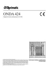
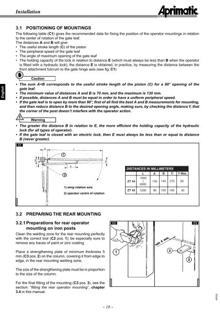
3.1 POSITIONING OF MOUNTINGS<br />
The following table (C1) gives the recommended data for fi xing the position of the operator mountings in relation<br />
to the center of rotation of the gate leaf.<br />
The distances A and B will give:<br />
• The useful stroke length (C) of the piston<br />
• The peripheral speed of the gate leaf<br />
• The angle of maximum opening of the gate leaf<br />
• The holding capacity of the lock in relation to distance E (which must always be less than B when the operator<br />
is fitted with a hydraulic lock); the distance E is obtained, in practice, by measuring the distance between the<br />
front attachment fulcrum to the gate hinge axis (see fi g. C1)<br />
English<br />
Caution<br />
• The sum A+B corresponds to the useful stroke length of the piston (C) for a 90° opening of the<br />
gate leaf.<br />
• The minimum value of distances A and B is 70 mm, and the maximum is 130 mm.<br />
• If possible, distances A and B must be equal in order to have a uniform peripheral speed.<br />
• If the gate leaf is to open by more than 90°, first of all find the best A and B measurements for mounting,<br />
and then reduce distance B to the desired opening angle, making sure, by checking the distance Y, that<br />
the corner of the post doesn’t interfere with the operator action.<br />
!<br />
Warning<br />
• The greater the distance B in relation to E, the more efficient the holding capacity of the hydraulic<br />
lock (for all types of operator).<br />
• If the gate leaf is closed with an electric lock, then E must always be less than or equal to distance<br />
B (never greater).<br />
C1<br />
1<br />
2<br />
1) wing rotation axis<br />
2) operator centre of rotation<br />
DISTANCES IN MILLIMETERS<br />
L A B C Y Max.<br />
ZT 44<br />
1200<br />
÷ 130 140 275 90<br />
4000<br />
ZT 42 1200 90 100 190 40<br />
AP030007<br />
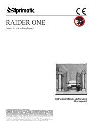
3.2 PREPARING THE REAR MOUNTING<br />
3.2.1 Preparations for rear operator<br />
mounting on iron posts<br />
Clean the welding zone for the rear mounting perfectly<br />
with the correct tool (C2 pos. 1); be especially sure to<br />
remove any traces of paint or zinc coating.<br />
Place a strengthening plate of minimum thickness 5<br />
mm (C3 pos. 2) on the column, covering it from edge to<br />
edge, in the rear mounting welding zone.<br />
The size of the strengthening plate must be in proportion<br />
to the size of the column.<br />
C2<br />
C3<br />
For the final fitting of the mounting (C3 pos. 3), see the<br />
section: “fi tting the rear operator mounting”, chapter<br />
3.4 in this manual.<br />
AP030008<br />
AP030009<br />
AP030<br />
- 18 -