
You also want an ePaper? Increase the reach of your titles
YUMPU automatically turns print PDFs into web optimized ePapers that Google loves.
R<br />
Installation<br />
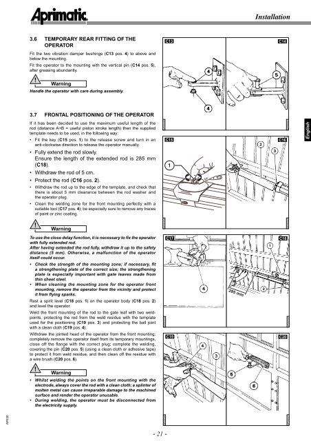
3.6 TEMPORARY REAR FITTING OF THE<br />
OPERATOR<br />
C13<br />
C14<br />
Fit the two vibration damper bushings (C13 pos. 4) to above and<br />
below the mounting.<br />
Fit the operator to the mounting with the vertical pin (C14 pos. 5),<br />
after greasing abundantly.<br />
!<br />
Warning<br />
Handle the operator with care during assembly.<br />
3.7 FRONTAL POSITIONING OF THE OPERATOR<br />
If it has been decided to use the maximum useful length of the<br />
rod (distance A+B = useful piston stroke length) then the supplied<br />
template needs to be used, in the following way:<br />
• Fit the key (C15 pos. 1) to the release screw and turn in an<br />
anti-clockwise direction to release the operator manually.<br />
AP030020<br />
C15<br />
C16<br />
AP030021<br />
English<br />
• Fully extend the rod slowly.<br />
Ensure the length of the extended rod is 285 mm<br />
(C18).<br />
• Withdraw the rod of 5 cm.<br />
1<br />
• Protect the rod (C16 pos. 2).<br />
• Withdraw the rod up to the edge of the template, and check that<br />
there is about 5 mm clearance between the rod washer and<br />
the operator plug.<br />
• Clean the welding zone for the front mounting perfectly with a<br />
suitable tool (C17 pos. 4); be especially sure to remove any traces<br />
of paint or zinc coating.<br />
!<br />
Warning<br />
AP030034<br />
AP030023<br />
To use the close delay function, it is necessary to fix the operator<br />
with fully extended rod.<br />
After having extended the rod fully, withdraw it up to the safety<br />
distance (5 mm). Otherwise, a malfunction of the operator<br />
itself could occur.<br />
C17<br />
• Check the strength of the mounting zone; if necessary, fit<br />
a strengthening plate of the correct size; the strengthening<br />
plate is especially important with gate leaves made from<br />
thin sheet steel.<br />
• When cleaning the mounting zone for the operator front<br />
mounting, remove the operator from the vicinity and protect<br />
it from flying sparks.<br />
Rest a spirit level (C18 pos. 1) on the operator body (C18 pos. 2)<br />
and level the operator.<br />
Weld the front mounting of the rod to the gate leaf with two weldpoints,<br />
protecting the rod from the weld residue with the template<br />
used for the positioning (C19 pos. 3) and protecting the ball joint<br />
with a clean cloth (C19 pos. 4).<br />
Withdraw the jointed head of the operator from the front mounting;<br />
completely remove the operator itself from its temporary mountings,<br />
close off the fl ange with the correct plug; complete the welding,<br />
covering the pin (C20 pos. 5) (using a clean cloth or adhesive tape)<br />
to protect it from weld residue, and then clean off the residue with<br />
a wire brush (C20 pos. 6).<br />
C19<br />
C20<br />
!<br />
Warning<br />
• Whilst welding the points on the front mounting with the<br />
electrode, always cover the rod with a clean cloth; a splinter of<br />
molten metal can cause irreparable damage to the machined<br />
surface and render the operator unusable.<br />
• During welding, the operator must be disconnected from<br />
the electricity supply.<br />
AP030<br />
C18<br />
285 mm<br />
AP030024<br />
AP030026<br />
AP030027<br />
AP030025<br />
- 21 -