
You also want an ePaper? Increase the reach of your titles
YUMPU automatically turns print PDFs into web optimized ePapers that Google loves.
Installation<br />
R<br />
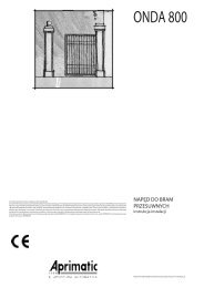
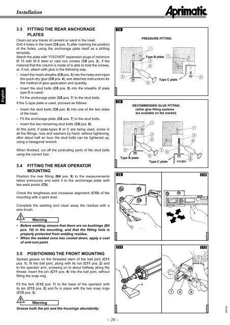
3.3 FITTING THE REAR ANCHORAGE<br />
PLATES<br />
Clean out any traces of cement or sand in the inset.<br />
Drill 4 holes in the inset (C8 pos. 1),after marking the position<br />
of the holes, using the anchorage plate itself as a drilling<br />
template.<br />
Attach the plate with “FISCHER” expansion plugs of minimum<br />
Ø 15 with M 8 steel or cast iron screws (C8 pos. 2), if the<br />
material that the column is made of is able to hold the screws,<br />
or, if not, attach with glue in the following way:<br />
C8<br />
PRESSURE FITTING<br />
Type B plate<br />
- Insert the mesh sheaths (C8 pos. 3) into the holes and inject<br />
the quick-dry glue (C8 pos. 4); see attached instructions for<br />
the method of glue application and quantity.<br />
Type C plate<br />
English<br />
- Insert the stud bolts (C8 pos. 5) into the sheaths (if plate<br />
type B is used)<br />
- Fit the anchorage plate (C8 pos. 7) to the stud bolts.<br />
If the C-type plate is used, proceed as follows:<br />
- Insert the stud bolts (C8 pos. 5) into one of the two sides<br />
of the inset.<br />
AP030014<br />
C8<br />
RECOMMENDED GLUE FITTING<br />
(other glue fitting systems<br />
are available on the market)<br />
- Fit the anchorage plate (C8 pos. 7) to the stud bolts.<br />
- Insert the two remaining stud bolts (C8 pos. 8).<br />
At this point, if plate-types B or C are being used, screw in<br />
all the fi ttings, nuts and washers by hand, without tightening;<br />
after about half an hour the stud bolts can be tightened up,<br />
using a hexagonal wrench.<br />
When fi nished, cut off the protruding parts of the stud bolts<br />
using the correct tool.<br />
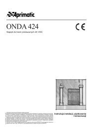
3.4 FITTING THE REAR OPERATOR<br />
MOUNTING<br />
Position the rear fi tting (B4 pos. 9) to the measurements<br />
taken previously and weld it to the anchorage plate with<br />
two weld points (C9).<br />
AP030015<br />
C9<br />
Type B plate<br />
Type C plate<br />
C10<br />
Check the lengthwise and crosswise alignment (C10) of the<br />
mounting with a spirit level.<br />
Complete the welding and clean away the residue with a<br />
wire brush.<br />
!<br />
Warning<br />
• Before welding, ensure that there are no bushings (B4<br />
pos. 10) in the mounting, and that the fitting hole is<br />
properly protected from welding residue.<br />
• When the welded zone has cooled down, apply a coat<br />
of anti-rust paint.<br />
AP030016<br />
AP030017<br />
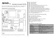
C11<br />
C12<br />
3.5 POSITIONING THE FRONT MOUNTING<br />
Spread grease on the threaded stem of the ball joint (C11<br />
pos. 1), fi t the ball joint, along with its nut (C11 pos. 2) and<br />
to the operator arm, screwing on to about halfway along the<br />
thread. Insert the pin (C11 pos. 4) into the ball joint, without<br />
fitting the snap ring.<br />
1<br />
2<br />
Fit the fork (C12 pos. 1) to the base of the operator with<br />
its pin (C12 pos. 2) and fi x in place with the two snap rings<br />
(C12 pos. 3).<br />
4<br />
!<br />
Warning<br />
Grease both the pin and the housings abundantly.<br />
AP030018<br />
AP030019<br />
AP030<br />
- 20 -