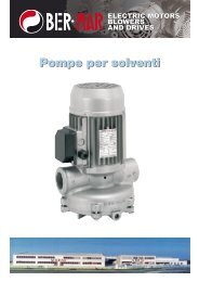
Motori Asincroni Vettoriali - Bermar.it
Motori Asincroni Vettoriali - Bermar.it
Motori Asincroni Vettoriali - Bermar.it

You also want an ePaper? Increase the reach of your titles
YUMPU automatically turns print PDFs into web optimized ePapers that Google loves.
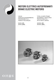
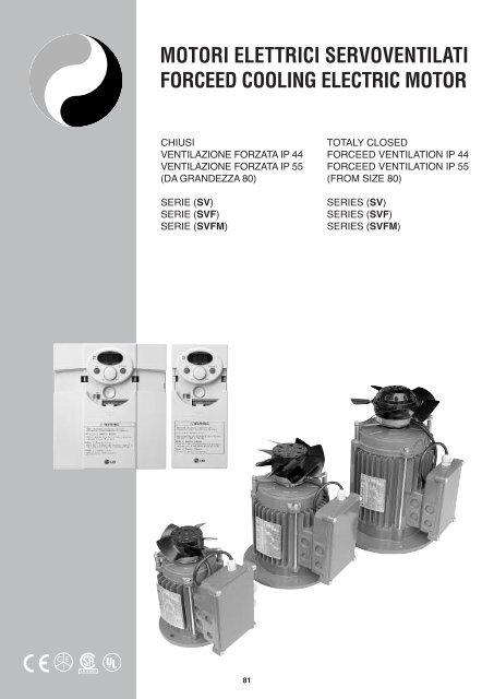
MOTORI ELETTRICI SERVOVENTILATI<br />
FORCEED COOLING ELECTRIC MOTOR<br />
CHIUSI<br />
VENTILAZIONE FORZATA IP 44<br />
VENTILAZIONE FORZATA IP 55<br />
(DA GRANDEZZA 80)<br />
SERIE (SV)<br />
SERIE (SVF)<br />
SERIE (SVFM)<br />
TOTALY CLOSED<br />
FORCEED VENTILATION IP 44<br />
FORCEED VENTILATION IP 55<br />
(FROM SIZE 80)<br />
SERIES (SV)<br />
SERIES (SVF)<br />
SERIES (SVFM)<br />
LR 91167<br />
®<br />
81
B3 IM B3 IM1001<br />
DIMENSIONI FORMA COSTRUTTIVA<br />
OVERALL DIMENSIONS<br />
B3 (CEI 2-14) IM B3 (IEC 34-7 Code I) IM 1001 (IEC 34-7 Code II)<br />
FRAME H A B C R K V L L2 G G1 G2 G3 U A1 B1 D E d<br />
63 63 100 80 40 95 7 134 243 220 167 102 127 125 80 120 100 11K6 23 M4<br />
71 71 112 90 45 95 10 156 273 243 185 113 145 138 91 135 109 14K6 30 M5<br />
80 80 125 100 50 115 11 176 315 275 210 129 161 155 103 154 125 19K6 40 M6<br />
90C 90 140 100 56 115 11 194 352 302 225 135 176 178 109 170 125 24K6 50 M8<br />
90L 90 140 125 56 115 11 220 378 328 225 135 176 178 109 170 150 24K6 50 M8<br />
100 100 160 140 63 115 12 246 423 363 247 146 198 195 120 192 166 28K6 60 M8<br />
112 112 190 140 70 112 14 267 466 406 267 154 222 223 131 220 175 28K6 60 M8<br />
132C 132 216 140 89 105 13 282 540 460 310 177 271 258 122 256 180 38K6 80 M10<br />
132M/L 132 216 178 89 105 13 399 579 499 310 177 271 258 122 256 218 38K6 80 M10<br />
160C 160 254 210 108 150 14 230 750 640 385 234 325 315 182 320 270 42K6 110 M12<br />
160M/L 160 254 254 108 150 14 230 800 686 385 234 325 315 182 320 310 42K6 110 M12<br />
X X1 K1 C1 P H1 h b t<br />
23 22 10 91 Pg11 8 4 4 12,5<br />
25 26 14 100 Pg11 9 5 5 16<br />
29 27 14 116 Pg13,5 10 6 6 21,5<br />
32 30 14 134 Pg16 11 7 8 27<br />
32 30 14 134 Pg16 11 7 8 27<br />
38 36 21 154 Pg16 12 7 8 31<br />
40 40 18 183 Pg16 15 7 8 31<br />
40 43 21 215 Pg21 18 8 10 41<br />
40 43 21 215 Pg21 18 8 10 41<br />
58 64 25 325 Pg21 23 8 12 45<br />
58 64 25 325 Pg21 23 8 12 45<br />
82
B5 IM B5 IM3001<br />
DIMENSIONI FORMA COSTRUTTIVA<br />
OVERALL DIMENSIONS<br />
B5 (CEI 2-14) IM B5 (IEC 34-7 Code I) IM 3001 (IEC 34-7 Code II)<br />
FRAME P N M Q R S V L L2 G2 G3 U F<br />
63 140 95J6 115 2,5 95 9 137 246 223 102 125 80 9,5<br />
71 160 110J6 130 2,5 95 11 161 278 248 113 138 91 9,5<br />
80 200 130J6 165 2,5 115 11 180 319 279 129 155 103 11,5<br />
90C 200 130J6 165 3,0 115 11 198 357 307 135 178 109 11,5<br />
90L 200 130J6 165 3,0 115 11 224 481 331 135 178 109 11,5<br />
100 250 180J6 215 3,5 115 14 251 430 370 146 195 120 14<br />
112 250 180J6 215 3,5 112 14 270 469 409 154 223 131 14<br />
132C 300 230J6 265 4,0 105 14 284 542 462 177 258 112 14<br />
132M/L 300 230J6 265 4,0 105 14 322 582 502 177 258 112 14<br />
160C 350 250J6 300 5,0 150 20 230 750 641 320 315 182 18<br />
160M/L 350 250J6 300 5,0 150 20 230 800 686 320 315 182 18<br />
D E d h b t<br />
11K6 23 M4 4 4 12,5<br />
14K6 30 M5 5 5 16<br />
19K6 40 M6 6 6 21,5<br />
24K6 50 M8 7 8 27<br />
24K6 50 M8 7 8 27<br />
28K6 60 M8 7 8 31<br />
28K6 60 M8 7 8 31<br />
38K6 80 M10 8 10 41<br />
38K6 80 M10 8 10 41<br />
42K6 110 M12 8 12 45<br />
42K6 110 M12 8 12 45<br />
83
B14 IM B14 IM3601<br />
DIMENSIONI FORMA COSTRUTTIVA<br />
OVERALL DIMENSIONS<br />
B14 (CEI 2-14) IM B14 (IEC 34-7 Code I) IM 3601 (IEC 34-7 Code II)<br />
FRAME P N M Q R V L L2 G G1 G3 U F**<br />
63 90 60J6 75 2,5 95 137 246 223 163 102 125 80 M5<br />
71 105 70J6 85 2,5 95 161 278 248 182 113 138 91 M6<br />
80 120 80J6 100 2,5 115 180 319 279 207 129 155 103 M6<br />
90C 140 95J6 115 3,0 115 198 357 307 217 135 178 109 M8<br />
90L 140 95J6 115 3,0 115 224 481 331 217 135 178 109 M8<br />
100 160 110J6 130 3,5 115 251 430 370 240 146 195 120 M8<br />
112 160 110J6 130 3,5 112 270 469 409 260 154 223 131 M8<br />
132C 200 130J6 165 4,0 105 284 542 465 305 177 258 122 M10<br />
132M/L 200 130J6 165 4,0 105 322 582 502 304 177 258 122 M10<br />
160C 250 180J6 215 4,0 150 230 700 591 400 234 315 182 M12<br />
160M/L 250 180J6 215 4,0 150 230 750 636 400 234 315 182 M12<br />
D E d h b t<br />
11K6 23 M4 4 4 12,5<br />
14K6 30 M5 5 5 16<br />
19K6 40 M6 6 6 21,5<br />
24K6 50 M8 7 8 27<br />
24K6 50 M8 7 8 27<br />
28K6 60 M8 7 8 31<br />
28K6 60 M8 7 8 31<br />
38K6 80 M10 8 10 41<br />
38K6 80 M10 8 10 41<br />
42K6 110 M12 8 12 45<br />
42K6 110 M12 8 12 45<br />
84
DATI TECNICI SERVOVENTOLE<br />
FORCEED VENTILATION TECHNICAL DATA<br />
MOTORE TIPO VENTOLA TIPO POTENZA VELOCITÀ TENSIONE I d BA M 3 /h ARIA<br />
MOTOR TYPE FAN TYPE POWER FAN SPEED SUPPLY VOLT AMPS NOISE M 3 /h AIR<br />
SV 63 A 2 D 107 25 W 2650 / 3000 2 X 230 0,10 45 180<br />
SV 71 A 2 D 107 25 W 2650 / 3000 2 X 230 0,10 45 180<br />
SV 80 A 2 D 130 45 W 2800 / 3250 2 X 230 0,15 52 350<br />
SV 90 A 2 D 130 45 W 2800 / 3250 2 X 230 0,15 55 370<br />
SV 100 A 2 D 170 60 W 2600 / 2900 3 X 230/400 0,18 / 0,10 68 780<br />
SV 112 A 2 D 200 70 W 2600 / 2900 3 X 230/400 0,20 / 0,12 68 900<br />
SV 132 A 2 D 250 150 W 2450 / 2550 3 X 230/400 0,25 / 0,15 73 1800<br />
SV 160 A 2 D 250 150 W 2430 / 2500 3 X 230/400 0,28 / 0,16 75 1850<br />
CARATTERISTICHE DI RENDIMENTO MOTORI CON VENTILAZIONE FORZATA<br />
ELECTRIC MOTORS WITH FORCEED VENTILATION PERFORMANCE<br />
4 POLE ELECTRIC MOTOR<br />
MOTORI A 4 POLE<br />
150% OVERLOAD LIMIT<br />
150% SOVRACCARICO MASSIMO<br />
120% OVERLOAD LIMIT CONTINUOUS SERVICE<br />
120% SOVRACCARICO MASSIMO SERVIZIO CONTINUO<br />
2 POLE ELECTRIC MOTOR<br />
MOTORI A 2 POLI<br />
150% OVERLOAD LIMIT<br />
150% SOVRACCARICO MASSIMO<br />
120% OVERLOAD LIMIT CONTINUOUS SERVICE<br />
120% SOVRACCARICO MASSIMO SERVIZIO CONTINUO<br />
85
SCHEMA COLLEGAMENTO MOTORE SERVOVENTILAZIONE A DUE E TRE FASI<br />
CONNECTION DIAGRAM OF FORCEED VENTILATION WITH TWO AND THREE FASES MOTOR<br />
86
1 COPRIVENTOLA FAN COVER<br />
2 VITE M4X8 SCREW M4x8<br />
3 VENTOLA ELETTRICA ELECTRIC FAN<br />
4 SCUDO POSTERIORE END BELL<br />
5 ANELLA COMPENSATRICE SHAFT SPRING<br />
6 CUSCINETTO POSTERIORE END BEARING<br />
7 SUPPORTO VENTOLA FAN SUPPORT<br />
8 VITE M5x20 SCREW M5x20<br />
9 TENUTA ALBERO SEAL SHAFT<br />
10 ALBERO+ROTORE ROTOR+DRIVE SHAFT<br />
11 CHIAVETTA DRIVE KEY<br />
12 CUSCINETTO ANTERIORE DRIVE BEARING<br />
13 CARCASSA MOTORE MOTOR CASE<br />
14 PERNO SERRAGGIO MOTORE ASSEMBLING SCREW<br />
15 MORSETTIERA TERMINAL BOARD<br />
16 VITE M4x16 SCREW M4x16<br />
17 SUPPORTO COVER BOX SUPPORT<br />
18 COPRIMORSETTIERA TERMINAL BOARD<br />
19 VITE M5x25 SCREW M5x25<br />
20 STATORE+AVVOLGIMENTO CASE+WINDING<br />
21 SCUDI ANTERIORI DRIVE END BELL<br />
22 MORSETTIERA VENTOLA FAN TERMINAL BOARD<br />
87
NOTE<br />
88
MOTORI ELETTRICI ASINCRONI<br />
VETTORIALI PER USO CON INVERTER<br />
VECTOR ASINCHRONOUS ELECTRIC<br />
MOTORS FOR VARIABLE FREQUENCY<br />
DRIVE DUTY<br />
SERIE (SVF)<br />
Servoventilati autofrenanti<br />
SERIE (SVC)<br />
Servoventilati con encoder<br />
SERIE (SVFC)<br />
Servoventilati con freno<br />
ed encoder<br />
SERIES (SVF)<br />
Forceed ventilation w<strong>it</strong>h brake<br />
SERIES (SVC)<br />
Forceed ventilation<br />
w<strong>it</strong>h encoder<br />
SERIES (SVFC)<br />
Forceed ventilation w<strong>it</strong>h brake<br />
and encoder<br />
LR 91167<br />
®<br />
89
DETTAGLI PER LA SERIE DI MOTORI<br />
S/SV/SVF/SVC/SVFC<br />
PREDISPOSTI PER FUNZIONAMENTO CON<br />
INVERTER O COME SERVOMOTORI<br />
CLASSIFICAZIONE:<br />
TECHNICAL DETAILS OF THE<br />
S/SV/SVF/SVC/SVFC<br />
SERIES FOR OPERATION WITH FREQUENCY<br />
CONVERTORS OF AS SERVOMOTORS<br />
UNIT CLASSIFICATION:<br />
S<br />
<strong>Motori</strong> standard 2 o 4 poli<br />
S<br />
Standard 2 or 4 poles<br />
SV<br />
Servoventilati 2 o 4 poli<br />
SV<br />
Servoventilated 2 or 4 poles<br />
SVF<br />
Autofrenanti servoventilati 2 o 4 poli<br />
SVF<br />
Self Braking servoventilated 2 or 4 poles<br />
SVC<br />
Servoventilati con encoder 2 o 4 poli<br />
SVC<br />
Servoventilated w<strong>it</strong>h encoder 2 or 4 poles<br />
SVFC<br />
Servoventilati autofrenanti con encoder 2 o 4 poli<br />
SVFC<br />
Servoventilated self braking w<strong>it</strong>h encoder 2 or 4 poles<br />
I motori sopra menzionati sono progettati e costru<strong>it</strong>i per il funzionamento<br />
e l’utilizzo sia nelle trasmissioni a veloc<strong>it</strong>à variabile<br />
con inverter sia come applicazione come servomotori. I<br />
motori descr<strong>it</strong>ti nella presente sezione offrono una considerevole<br />
riserva di potenza ed una eccezionale curva termica in<br />
relazione alle sollec<strong>it</strong>azioni a cui sono sottoposti nei confronti<br />
della rispettiva serie unificata standard, questa differenza è<br />
meglio evidenziata nella comparazione del grafico nella<br />
tabella No 1.<br />
Potenza<br />
La potenza dei motori descr<strong>it</strong>ti è considerata in servizio continuo<br />
(S1) con tensioni unificate secondo IEC 38. Per tutti i<br />
valori di funzionamento, di potenza e di assorbimento facciamo<br />
riferimento alla sezione dei motori standard inclusa nel<br />
presente catalogo.<br />
Tensioni di alimentazione<br />
I motori descr<strong>it</strong>ti nella presente sezione sono forn<strong>it</strong>i per il<br />
mercato Europeo con tensione di alimentazione unificata a<br />
230/400 Volts e a 200/460 per il mercato Americano.<br />
Frequenza<br />
La frequenza di riferimento è di Hz 50 per il mercato Europeo<br />
e di Hz 60 per il mercato Americano.<br />
Classe d’isolamento<br />
La classe d’isolamento per questi motori è in classe H<br />
(sovratemperatura degli avvolgimenti 180 °C).<br />
Giri motore<br />
Standard come da catalogo.<br />
Protezione termica<br />
La protezione termica degli avvolgimenti è ottenuta con l’applicazione<br />
di termoprotettori inser<strong>it</strong>i nell’avvolgimento, bimetallici<br />
o a resistenza, i terminali dei termoprotettori devono<br />
essere collegati in serie al sistema di comando del motore o<br />
negli appos<strong>it</strong>i morsetti dell’inverter. Con il sistema dei protettori<br />
bimetallici è possibile garantire una accettabile protezione<br />
termica del motore, è senz’altro da preferire per questi<br />
motori la protezione termica a resistenza (PTC) la quale<br />
garantisce una assoluta certezza la protezione termica della<br />
macchina durante un’anormale surriscaldamento.<br />
Controllo radio interferenze normativa EMC<br />
I motori asincroni con rotori a gabbia di scoiattolo sono considerati<br />
protetti contro i disturbi di radiofrequenza secondo la<br />
normativa DIN 0875 con grado di protezione FN.<br />
The motors of the above-mentioned series have been designed<br />
both for the use of variable speed transmissions w<strong>it</strong>h<br />
frequency inverters and for applications of greater dynamics<br />
in servotechnique.<br />
Indeed these motors offer a considerable reserve of power<br />
w<strong>it</strong>h a considerably lower corresponding heat characteristic<br />
than the unified series I E C.<br />
This difference may be seen better by comparing the M/Ms<br />
ratio in diagram no.1.<br />
Power<br />
The powers of the motors shown in this list apply to continuous<br />
operation (S1) w<strong>it</strong>h voltage rating as in IEC 38.<br />
For other types of operation, we are referring to the diagrams<br />
shown in the list of unified motors.<br />
Voltages<br />
The motors of these series are supplied for the European<br />
market at the unified voltage of 230-400 volts IEC 38 and at<br />
200-460 Hz 60 for the American market.<br />
Frequency<br />
The values shown refer to the frequency of 50 Hz.<br />
Insulation class<br />
The insulation corresponds to class H (winding overtemperature<br />
180 °C).<br />
Number of revolutions<br />
Standard number of revolutions.<br />
Motor protection<br />
To protect the windings of an electric three-phase motor w<strong>it</strong>h<br />
alternating current against heat overload, proceed as follows:<br />
f<strong>it</strong>ting of a temperature sensor in the stator winding w<strong>it</strong>h cold<br />
conductor connected to a release device or to the special terminals<br />
of the inverter.<br />
W<strong>it</strong>h this system <strong>it</strong> is possible to guarantee complete thermal<br />
protection for most motor types.<br />
Screening against radio disturbance<br />
Asynchronous motors w<strong>it</strong>h squirrel-cage rotors are considered<br />
protected against radio disturbance according to DIN<br />
0875 w<strong>it</strong>h degree of protection FN.<br />
Systems of transducer and their connections<br />
Incremental angular speed transducers act as recorders of<br />
the measuring value for rotational movement; they tran-sform<br />
the rotational movement into electric signals which can be<br />
90
Sistema della trasmissione del segnale dei trasduttori<br />
I trasduttori normalmente utilizzati sono encoders o dinamo<br />
tachimetriche, gli encoders da noi utilizzati sono di primaria<br />
marca (Stegmann o Hidenain), sono fabbricati con le più<br />
moderne tecnologie per garantire la massima affidabil<strong>it</strong>à<br />
durante il gravoso servizio a cui sono sottoposti.<br />
Gli encoder incrementali usati sono atti a misurare il valore<br />
del movimento rotatorio dell’albero di trasmissione, essi trasformano<br />
il movimento rotatorio in segnale elettrico il quale a<br />
sua volta è elaborato dal sistema di acquisizione dati al quale<br />
essi sono collegati.<br />
Sostanzialmente il segnale di partenza che è una veloc<strong>it</strong>à<br />
angolare rappresentata come una curva sinusoidale di corrente,<br />
dopo una accurata dig<strong>it</strong>alizzazione elettronica ottenuta<br />
tram<strong>it</strong>e la lettura del disco rotativo dell’encoder dalla propria<br />
fotocellula, il segnale di partenza è trasformato in una serie di<br />
impulsi ortogonali i quali sono a loro volta inviati al sistema di<br />
controllo della rotazione.<br />
Le dinamo tachimetriche sono meno sofisticate e meccanicamente<br />
meno delicate, esse sono consigliate quando il sistema<br />
necess<strong>it</strong>a solamente della lettura della veloc<strong>it</strong>à dell’albero<br />
di trasmissione.<br />
Il sistema di rotazione genera una tensione conosciuta alle<br />
varie differenti veloc<strong>it</strong>à e permette tram<strong>it</strong>e la dig<strong>it</strong>alizzazione<br />
della stessa il controllo in automatico della regolazione di<br />
veloc<strong>it</strong>à del sistema.<br />
Valori della vibrazione dei motori secondo DIN-ISO 2373<br />
GRADO No. Giri Valore lim<strong>it</strong>e delle vibrazioni<br />
alla veloc<strong>it</strong>à (mm/s) con<br />
frequenze da 10 a 1.000 Hz<br />
RIDOTTA Da 600 a 1800 0.71<br />
Da 1800 a 4000 1.12<br />
SPECIAL Da 600 a 1800 0.45<br />
Da 1800 a 4000 0.71<br />
Tolleranze +/- 10%<br />
Specifiche meccaniche<br />
I motori della presente sezione corrispondono alle normative<br />
DIN-IEC e specialmente alla direttiva IEC 34 così come alle<br />
normative VDE 0530 in relazione alle macchine rotanti parte 1.<br />
DIN 42673<br />
<strong>Motori</strong> con fissaggio tram<strong>it</strong>e piedi<br />
DIN 42677 <strong>Motori</strong> con fissaggio tram<strong>it</strong>e flangia IEC B 5<br />
DIN 42948 <strong>Motori</strong> con fissaggio tram<strong>it</strong>e flangia IEC B 14<br />
DIN 748/3<br />
<strong>Motori</strong> con estrem<strong>it</strong>à d’albero cilindriche<br />
Carcasse<br />
Le carcasse dei motori rappresentati sono in lega d’alluminio<br />
pressofuso, il raffreddamento della superficie del motore è<br />
assicurata dalle alette ricavate sulle carcasse le quali permettono<br />
un ottimo smaltimento del calore residuo. I piedi di<br />
supporto per i motori in forma B 3 sono fusi assieme alla carcassa<br />
motore.<br />
Forme costruttive<br />
I motori sono costru<strong>it</strong>i in conform<strong>it</strong>à alle direttive DIN-IEC 34<br />
parte 7 in tre diverse configurazioni, B 3 - B 5 - B 14. Le<br />
dimensioni costruttive sono illustrate nella presente sezione.<br />
elaborated into numerical commands which may be programmed<br />
in memory or adjustment devices or used alone for pos<strong>it</strong>ion<br />
indication. Incremental angular speed transducers which<br />
function according to the principle of photoelectric measurement<br />
of fine grid scanning, produce a degree of accuracy of<br />
measurement of up to less than a second of arc. The starting<br />
signal of the angular speed transducer represents a curve of<br />
sinusoidal current, after enabling electronic dig<strong>it</strong>alization, the<br />
starting signal is converted into a series of orthogonal impulses.<br />
These electronics are incorporated into the transducer.<br />
Recommended values according to DIN-ISO 2373<br />
GRADE No. Revs Lim<strong>it</strong> values of the oscillation<br />
speed (mm/s) in frequencies<br />
from 10 to 1.000 Hz<br />
REDUCED from 600 to 1800 0.71<br />
from 1800 to 4000 1.12<br />
SPECIAL from 600 to 1800 0.45<br />
from 1800 to 4000 0.71<br />
Tolerances +/- 10%<br />
Mechanical specifications<br />
The motors correspond to the relevant DIN-IEC regulations,<br />
especially IEC 34 as well as the VDE 0530 provisions for<br />
rotating electrical machines part 1.<br />
DIN 42673<br />
DIN 42677<br />
DIN 42948<br />
DIN 748/3<br />
w<strong>it</strong>h feet<br />
w<strong>it</strong>h flange B5<br />
w<strong>it</strong>h flange B14<br />
w<strong>it</strong>h cylindrical end of the shaft<br />
Frames<br />
Diecast frames in light aluminium alloy cooled on the surface<br />
by means of cooling fins. The support feet are built into the<br />
frame.<br />
Forms of construction<br />
The motors are manufactured according to the regulations<br />
DIN-IEC 34 part 7 in the three main constructing forms (B3,<br />
B5, B14). They are illustred in the dimensioned drawings of<br />
this catalogue.<br />
Shaft end<br />
The motors are f<strong>it</strong>ted as standard w<strong>it</strong>h the cylindrical shaft<br />
end in accordance w<strong>it</strong>h DIN 748/3.<br />
Coupling K 6 up to diameter 28<br />
Coupling K 8 up to diameter 60<br />
Coupling m 8 over diameter 60<br />
Tongue according to DIN 8886 sheet 1.<br />
Hole from centre according to DIN 332 sheet 2.<br />
Inclination of the flanges<br />
In the normal versions the standard accuracies are respected:<br />
Tolerance according to DIN 42955, IEC 72 between<br />
shaft and flange level +/- 0.1 mm.<br />
We can supply more precise tolerances at an extra charge<br />
+/- 0.05.<br />
91
Albero motore<br />
Le estrem<strong>it</strong>à degli alberi motore sono prodotte in conform<strong>it</strong>à<br />
alla normativa DIN 748/3 in relazione alle estrem<strong>it</strong>à cilindriche.<br />
Accoppiamento k 6 fino al diametro 38<br />
Accoppiamento k 8 fino al diametro 60<br />
Accoppiamento m 8 oltre al diametro 60<br />
Il foro di centraggio e il relativo filetto in testa all’albero sono<br />
secondo DIN 332 foglio 2.<br />
Centraggio flange<br />
Nella costruzione dei motori nelle versioni standard le tolleranze<br />
consigliate sono rispettate secondo DIN 42955 e IEC<br />
72 tra il piano della flangia e il piano dell’albero in +/- 0,1 mm.<br />
È possibile rispettare tolleranze più precise +/- 0.05 con un<br />
extrapezzo.<br />
Specifiche motori autofrenanti<br />
I motori elettrici di questa sezione equipaggiati con freno a<br />
molla, hanno le stesse caratteristiche meccaniche dei motori<br />
autofrenanti della serie unificata.<br />
Per informazioni dettagliate fare riferimento alla indicata<br />
sezione del catalogo.<br />
Ulteriori specifiche<br />
Maggiori informazioni si possono avere consultando la parte<br />
iniziale del presente catalogo e le relative sezioni dove sono<br />
contenute le parti in comune dei motori di questa sezione.<br />
Protezioni meccaniche<br />
I motori elettrici riportati nella presente sezione corrispondono<br />
alla protezione meccanica IP 54 secondo le norme DIN-<br />
IEC 34.<br />
I fori filettati per cavi di collegamento del motore e dei servizi<br />
ausiliari dello stesso sono predisposti a 180° tra loro, il connettore<br />
dell’encoder è fissato tram<strong>it</strong>e due v<strong>it</strong>i alla carcassa<br />
del motore e può essere orientato di 90° in 90° in riferimento<br />
al proprio asse.<br />
Diversi tipi di protezione sono disponibili su richiesta con<br />
sovraprezzo.<br />
Per maggiori informazioni fate riferimento alle pagine iniziali<br />
del catalogo nell’appos<strong>it</strong>a sezione che tratta i diversi tipi di<br />
protezione.<br />
Valori della rumoros<strong>it</strong>à<br />
I valori della rumoros<strong>it</strong>à sono stati misurati secondo la direttiva<br />
DIN 45835 in riferimento allo spazio con basso valore di<br />
livello di riflesso.<br />
L’intens<strong>it</strong>à del rumore in dB (A) è data dal livello di pressione<br />
acustica misurata sulla parte di trasmissione del motore (L),<br />
in conform<strong>it</strong>à con le raccomandazioni della normativa VDE<br />
0630 parte 9 rileviamo le misure della pressione acustica<br />
della sottoesposta tabella con misure fatte a un metro di<br />
distanza dalla macchina in funzione.<br />
Specifications for self-braking<br />
These motors of special construction, in the self-braking<br />
form, have the same mechanical characteristics of the brake<br />
as the unified version and are recognized as extremely reliable<br />
and easy to maintain.<br />
For the relative information please see the sections concerning<br />
these topics.<br />
Other specifications<br />
All the other specifications which regulate the electrical and<br />
mechanical manufacture in common w<strong>it</strong>h these motors of our<br />
electric motors can be found in our general catalogue.<br />
Types of protection<br />
The motors and the terminal board box correspond to the<br />
type of protection IP 54, according to DIN-IEC 34 regulations.<br />
The cables to connect w<strong>it</strong>h the motor may enter the terminal<br />
board box at 90° for each side.<br />
Further protection is available on request.<br />
For full comprehension of the degrees of protection please<br />
see the relative pages on general explanations section.<br />
Noise values<br />
Noise is measured according to DIN 45835 regulations in<br />
spaces w<strong>it</strong>h a low level of reflection.<br />
Noise intens<strong>it</strong>y in dB(A) is given by the level of the acoustic<br />
pressure of the measuring surface L, according to the regulations<br />
VDE 0630 part 9, this is the average spatial value of the<br />
levels of acoustic pressure measured at 1 metre away from<br />
the machine.<br />
Levels of pressure<br />
w<strong>it</strong>h nominal load w<strong>it</strong>h self ventilation<br />
SIZE<br />
Ls<br />
Db<br />
MEASURE<br />
Lpa<br />
dB 2 poles (A) dB 4 poles (A)<br />
Frame 63 8 54 45<br />
Frame 71 9 60 47<br />
Frame 80 9 60 48<br />
Frame 90 9 60 50<br />
Frame 100 9 65 54<br />
Frame 112 9 68 57<br />
Frame 132 10 70 59<br />
Frame 160 10 72 61<br />
All the values given for Lpa are subject to a tolerance of + 3<br />
dB (A). Sound power level A: Lwa = Lpa + Ls. The noise<br />
values for operation w<strong>it</strong>h convertor may be provided on<br />
request at an extra charge.<br />
Cooling fans<br />
In the case of self ventilation the motors are f<strong>it</strong>ted w<strong>it</strong>h radial<br />
bi-directional fans in shock proof thermostable plastic.<br />
n the case of servo-ventilation the motors are f<strong>it</strong>ted w<strong>it</strong>h aluminium<br />
fans powered by a 2 or 4 pole support motor placed<br />
axially to the main motor.<br />
92
Livello di pressione sonora al carico nominale su motori<br />
autoventilati<br />
For sizes up to MEC 90:<br />
single phase<br />
230V 50-60 Hz<br />
GRANDEZZA<br />
MISURA<br />
Ls<br />
Lpa<br />
Db dB 2 poli (A) dB 4 poli (A)<br />
Taglia 63 8 54 45<br />
Taglia 71 9 60 47<br />
Taglia 80 9 60 48<br />
Taglia 90 9 60 50<br />
Taglia 100 9 65 54<br />
Taglia 112 9 68 57<br />
Taglia 132 10 70 59<br />
Taglia 160 10 72 61<br />
Per tutti i valori rilevati in Lpa bisogna considerare una tolleranza<br />
di + 4 dB (A).<br />
Livello della potenza sonora A : Lwa = Lpa + Ls.<br />
Sono possibili rilevazioni di valori di rumore per motori collegati<br />
ad inverter con sovraprezzo.<br />
For sizes from MEC 100:<br />
tri-phase<br />
230-400V 50-60 Hz<br />
The blowers are protected by punched steel sheet cases.<br />
These cases open at the back of the motor and must therefore<br />
be left unobstructed for good motor ventilation.<br />
Radial ventilation is included for special motors.<br />
Oscillations (Operation in network)<br />
All the rotors are balanced dynamically w<strong>it</strong>h full tongue inserted<br />
according to regulations DIN-ISO 2373.<br />
The elements of the transmission to be f<strong>it</strong>ted at the end of<br />
the shaft should therefore be balanced w<strong>it</strong>hout the tongue.<br />
The motors are delivered standard in the reduced degree of<br />
oscillation intens<strong>it</strong>y.<br />
W<strong>it</strong>h the exception of the self-braking motors, the standard<br />
motors may be delivered balanced w<strong>it</strong>h special degree, at an<br />
extra charge.<br />
Ventilatori<br />
I motori elettrici autoventilati sono provvisti di una ventola in<br />
plastica bidirezionale la quale ruota alla stessa veloc<strong>it</strong>à dell’albero<br />
motore, non è possibile utilizzare motori autoventilati<br />
quando la veloc<strong>it</strong>à di rotazione scende sotto il 25% della<br />
veloc<strong>it</strong>à nominale o quando supera i 4.000 giri/min. Nel caso<br />
di motori servoventilati, il motore della servoventilazione è<br />
disposto assialmente al motore principale, è normalmente un<br />
2 o 4 poli e le pale di raffreddamento sono il lamiera d’acciaio<br />
stampata.<br />
L’utilizzo della ventilazione forzata è consigliata quando si<br />
presentano le condizioni di cui sopra, per maggiori e più dettagliate<br />
informazioni fate riferimento alla sezione dei motori<br />
servoventilati di questo catalogo.<br />
Nella tabella sono indicate le diverse alimentazioni delle<br />
servoventole.<br />
Fino a grandezza IEC 90:<br />
alimentazione monofase 1 x 230V 50-60 Hz<br />
Da grandezza IEC 100:<br />
alimentazione trifase 3 x 230-400V 50-60 Hz<br />
93
----------------------------------------------------- 2 POLI - 230/400V - 3000 GIRI - 50Hz -----------------------------------------------------<br />
Tipo kW HP Giri In In µ% Cos CN Ca/Cn Cm/Cn Ia / In J<br />
Type RPM V. 230 V. 400 ϕ Nm kgm 2<br />
63 C2 0,18 0,25 2740 1,03 0,60 66 0,74 0,63 3,4 2,7 4,3 0,000135<br />
63 S2 0,26 0,35 2755 1,73 1 67 0,68 0,90 3,3 2,4 3,7 0,000144<br />
63 L2 0,37 0,50 2795 2,16 1,25 69 0,67 1,27 3,3 2,9 4,5 0,000181<br />
71 C2 0,37 0,50 2800 1,9 1,1 72 0,75 1,26 2,4 2,0 4,4 0,000352<br />
71 S2 0,55 0,75 2800 2,59 1,5 71 0,79 1,88 2,2 2,0 4,4 0,000405<br />
80 C2 0,75 1 2820 3,11 1,8 78 0,80 2,54 2,2 2,1 4,8 0,000747<br />
80 S2 1,1 1,5 2810 4,67 2,7 79 0,84 3,74 2,4 2,1 5,2 0,000887<br />
90 SC2 1,5 2 2805 6,92 4 69 0,83 5,10 2,1 2,5 4,7 0,001365<br />
90 LS2 1,8 2,5 2820 7,78 4,5 73 0,86 6,10 2,1 2,6 5,0 0,001557<br />
90 LL2 2,2 3 2860 9,34 5,4 76 0,80 7,35 2,7 2,5 6,5 0,001802<br />
100 SC2 3 4 2850 11,24 6,5 78 0,90 10 2,6 3,1 6,4 0,003350<br />
100 LS2 4 5,5 2865 15,22 8,8 84 84 0,82 13,3 2,0 5,1 0,004050<br />
112 MC2 4 5,5 2885 16,26 9,4 80 0,82 13,2 3,1 2,9 6,9 0,006475<br />
112 LS2 5,5 7,5 2885 20,76 12 82 0,85 18,2 2,7 3,0 7,0 0,008575<br />
132 MC2 5,5 7,5 2882 23,35 13,5 81 0,87 18,2 2,1 2,9 5,6 0,010625<br />
132 LS2 7,5 10 2910 32,87 19 84 0,89 31,2 2,3 4,0 7,8 0,017125<br />
132 LL2 9,5 12,5 2900 39,79 23 81 0,86 36,2 2,5 4,2 7,6 0,017125<br />
160 SC2 11 15 2915 43,25 25 80 0,84 36,03 2,5 3,3 5,8 0,040000<br />
160 LS2 15 20 2935 53,67 31 87 0,88 48,8 2,3 3,4 7,8 0,051750<br />
160 LL2 18,5 25 2950 65,74 38 83 0,88 59,88 3,2 3,4 8,4 0,064000<br />
----------------------------------------------------- 4 POLI - 230/400V - 1500 GIRI - 50Hz -----------------------------------------------------<br />
Tipo kW HP Giri In In µ% Cos CN Ca/Cn Cm/Cn Ia / In J<br />
Type RPM V. 230 V. 400 ϕ Nm kgm 2<br />
63 C4 0,13 0,18 1280 0,77 0,45 58 0,70 0,97 1,9 1,6 2,3 0,000219<br />
63 S4 0,18 0,25 1295 0,95 0,55 59 0,72 1,33 2,1 1,8 2,8 0,000027<br />
63 L4 0,25 0,33 1307 1,03 0,60 64 0,72 1,82 2,1 1,7 3,0 0,000342<br />
71 C4 0,25 0,33 1390 1,55 0,9 68 0,67 1,72 3,1 2,5 4,2 0,000695<br />
71 S4 0,37 0,50 1370 2,24 1,3 64 0,70 2,58 2,5 2,0 3,1 0,000822<br />
80 C4 0,55 0,75 1390 2,59 1,5 71 0,76 3,78 2,2 2,3 4,0 0,001580<br />
80 S4 0,75 1 1380 4,15 2,4 70 0,73 5,19 2,3 2,3 4,1 0,001995<br />
90 SC4 1,1 1,5 1380 5,36 3,1 74 0,75 7,61 2,2 2,2 3,9 0,002500<br />
90 LS4 1,5 2 1400 6,74 3,9 77 0,73 10,2 2,4 2,6 4,4 0,003125<br />
90 LL4 1,8 2,5 1390 8,82 5,1 75 0,72 12,36 2,0 2,5 3,9 0,003725<br />
100 MC4 2,2 3 1396 10,89 6,3 75 0,81 15 1,8 2,4 4,1 0,004600<br />
100 LS4 3 4 1400 12,97 7,5 78 0,80 20,5 1,8 2,4 4,0 0,005825<br />
112 MS4 4 5,5 1450 16,43 9,5 80 0,81 26,3 2,1 2,9 5,3 0,013300<br />
132 SC4 5,5 7,5 1440 21,62 12,5 82 0,83 36,5 2,2 3,0 5,9 0,022400<br />
132 LS4 7,5 10 1445 27,68 16 83 0,85 49,6 2,2 3,0 6,6 0,029250<br />
132 LL4 9,2 12,5 1428 36,33 21 81 0,89 61,5 2,6 3,4 7,7 0,037250<br />
160 SC4 11 15 1450 42,38 24,5 80 0,84 72,44 1,7 2,8 6,5 0,081250<br />
160 LS4 15 20 1455 57,09 33 81 0,83 98,45 1,9 2,8 7,3 0,105750<br />
94
----------------------------------------------------- 6 POLI - 230/400V - 1000 GIRI - 50Hz -----------------------------------------------------<br />
Tipo kW HP Giri In In µ% Cos CN Ca/Cn Cm/Cn Ia / In J<br />
Type RPM V. 230 V. 400 ϕ Nm kgm 2<br />
63 C6 0,09 0,12 835 0,74 0,43 52 0,62 1,03 1,4 1,3 1,9 0,00033<br />
71 C6 0,18 0,25 865 1,24 0,72 66 0,69 1,98 1,9 1,6 2,3 0,00124<br />
71 S6 0,25 0,33 875 1,49 0,86 63 0,69 2,79 1,8 2,4 2,2 0,00124<br />
80 C6 0,37 0,50 900 2,32 1,34 60 0,70 3,92 1,5 1,9 2,7 0,00197<br />
80 S6 0,55 0,75 926 3,46 2,00 63 0,64 5,67 2,1 2,3 3,3 0,00247<br />
90 SC6 0,75 1 895 3,63 2,01 66 0,78 8 1,8 1,8 3,3 0,00318<br />
90 LS6 1,1 1,5 900 5,28 3,05 70 0,75 11,7 1,7 2 3,4 0,00478<br />
100 SC6 1,5 2 925 7,09 4,11 71 0,74 15,5 1,8 2,1 3,6 0,00673<br />
100 LS6 1,8 2,5 940 9,52 5,50 68 0,72 18,3 2,1 2,3 4 0,00943<br />
112 SC6 2,2 3 910 9,80 5,70 75 0,77 23 1,4 1,8 4 0,01418<br />
112 LS6 3 4 916 11,87 6,86 75 0,82 31 1,5 2,2 4,5 0,01870<br />
132 SC6 3 4 950 13,49 7,80 71 0,77 30,1 1,3 2 3,5 0,02353<br />
132LS6 4 5,5 950 17,82 10,11 75 0,77 42 1,3 2,2 4,3 0,00295<br />
132 LL6 5,5 7,5 955 23,01 13,55 77 0,78 55 1,5 2,3 4 0,03775<br />
160SC6 7,5 10 960 27,94 16,12 80 0,83 74,6 1,2 2,4 3 0,00813<br />
160 LS6 11 15 950 41,92 24,23 80 0,83 110,57 1,2 2,5 3 0,01058<br />
----------------------------------------------------- 4 POLI - 230/400V - 1500 GIRI - 50Hz -----------------------------------------------------<br />
Tipo kW HP Giri In In µ% Cos CN Ca/Cn Cm/Cn Ia / In J<br />
Type RPM V. 230 V. 400 ϕ Nm kgm 2<br />
71 C8 0,15 0,20 605 1,25 0,72 50 0,60 2,37 1,7 1,7 1,8 0,00082<br />
80 C8 0,25 0,35 680 1,87 1,08 56 0,62 3,52 1,5 1,7 2,4 0,00197<br />
90 SC8 0,37 0,50 695 2,77 1,60 54 0,61 5,10 1,6 2 2,7 0,00318<br />
90 LS8 0,55 0,75 685 3,72 2,15 58 0,65 7,67 1,7 1,9 2,8 0,00478<br />
100 SC8 0,75 1 695 3,98 2,30 64 0,72 10,3 1,4 1,7 2,9 0,00673<br />
100 LS8 1,1 1,5 695 6,57 3,80 62 0,68 15,1 1,8 1,9 2,9 0,00925<br />
112 SC8 1,5 2 690 7,79 4,50 68 0,71 20,8 1,3 2 2,9 0,01670<br />
132 SC8 2,2 3 705 11,07 6,40 69 0,73 29,8 1,5 2 3 0,02950<br />
132 LS8 3 4 710 14,88 8,60 70 0,72 40,4 1,5 2 3,2 0,03775<br />
160 SC8 4 5,5 715 17,39 10,05 77 0,73 53,4 1,4 2,2 3 0,8950<br />
160 LS8 5,5 7,5 720 22,66 13,10 81 0,76 72,9 1,4 2,6 3,6 0,11950<br />
160 LL8 7,5 10 710 29,41 17,00 82 0,77 100,8 1,3 2,8 3,6 0,15025<br />
1kW = 1,34 HP<br />
giri = veloc<strong>it</strong>à al min’<br />
In = corrente nominale a pieno carico<br />
µ% = rendimento<br />
Cos fi = Fattore di potenza<br />
J = momento di inerzia<br />
Cn = coppia nominale<br />
Ca/Cn = rapporto coppia avviamento/coppia nominale<br />
Cm/Cn = Rapporto coppia massima/coppia nominale<br />
la/ln = rapporto corrente di avviamento/corrente<br />
1kW = 1,34 HP<br />
giri = rated speed<br />
In = rated current<br />
µ% = efficiency<br />
Cos fi = power factor<br />
J = moment of inertia<br />
Cn = rated torque<br />
Ca/Cn = starting torque to rated torque<br />
Cm/Cn = maximum torque to rated torque<br />
la/ln = startin current to rated current<br />
95
SERIE SVF<br />
SERIES SVF<br />
B3 IM B3 IM1001<br />
DIMENSIONI FORMA COSTRUTTIVA<br />
OVERALL DIMENSIONS<br />
B3 (CEI 2-14) IM B3 (IEC 34-7 Code I) IM 1001 (IEC 34-7 Code II)<br />
FRAME H A B C R K V L L2 G G1 G2 G3 U A1 B1 D E d<br />
63 63 100 80 40 66 7 134 300 277 167 102 127 117 80 120 100 11K6 23 M4<br />
71 71 112 90 45 66 10 156 325 295 185 113 145 138 91 135 109 14K6 30 M5<br />
80 80 125 100 50 115 11 176 368 328 210 129 161 155 103 154 125 19K6 40 M6<br />
90 C 90 140 100 56 115 11 194 404 354 225 135 176 178 109 170 125 24K6 50 M8<br />
90 L 90 140 125 56 115 11 132 432 382 225 135 176 178 109 170 150 24K6 50 M8<br />
100 100 160 140 63 115 12 246 485 425 247 146 198 195 120 192 166 28K6 60 M8<br />
112 112 190 140 70 115 14 267 525 465 267 154 222 223 131 220 175 28K6 60 M8<br />
132 C 132 216 140 89 105 13 282 608 528 310 177 271 258 122 256 180 38K6 80 M10<br />
132 M/L 132 216 178 89 105 13 399 646 566 310 177 271 258 122 256 218 38K6 80 M10<br />
160 C 160 254 210 108 150 14 230 751 641 385 234 325 315 182 320 270 42K6 110 M12<br />
160 M/L 160 254 254 108 150 14 230 796 686 385 234 325 315 182 320 310 42K6 110 M12<br />
X X1 K1 C1 Z H1 h b t<br />
23 22 10 91 Pg 11 8 4 4 12,5<br />
25 26 14 100 Pg 11 9 5 5 16<br />
29 27 14 116 Pg 13,5 10 6 6 21,5<br />
32 30 14 134 Pg 16 11 7 8 27<br />
32 30 14 134 Pg 16 11 7 8 27<br />
38 36 21 154 Pg 16 12 7 8 31<br />
40 40 18 183 Pg 16 15 7 8 31<br />
40 43 21 215 Pg 21 18 8 10 41<br />
40 43 21 215 Pg 21 18 8 10 41<br />
58 64 25 325 Pg 21 23 8 12 45<br />
58 64 25 325 Pg 21 23 8 12 45<br />
96
SERIE SVF<br />
SERIES SVF<br />
B5 IM B5 IM3001<br />
DIMENSIONI FORMA COSTRUTTIVA<br />
OVERALL DIMENSIONS<br />
B5 (CEI 2-14) IM B5 (IEC 34-7 Code I) IM 3001 (IEC 34-7 Code II)<br />
FRAME P N M Q R S V L L2 G2 G3 U F<br />
63 140 95J6 115 2,5 95 9 137 300 277 102 117 80 9,5<br />
71 160 110J6 130 2,5 95 11 161 325 295 113 138 91 9,5<br />
80 200 130J6 165 2,5 115 11 180 368 328 129 155 103 11,5<br />
90C 200 130J6 165 3,0 115 11 198 404 354 135 178 109 11,5<br />
90L 200 130J6 165 3,0 115 11 224 432 382 135 178 109 11,5<br />
100 250 180J6 215 3,5 115 14 251 485 425 146 195 120 14<br />
112 250 180J6 215 3,5 112 14 270 525 465 154 223 131 14<br />
132C 300 230J6 265 4,0 105 14 284 608 528 177 258 112 14<br />
132M/L 300 230J6 265 4,0 105 14 322 646 566 177 258 112 14<br />
160C 350 250J6 300 5,0 150 20 230 751 641 320 315 182 18<br />
160M/L 350 250J6 300 5,0 150 20 230 796 686 320 315 182 18<br />
D E d h b t<br />
11K6 23 M4 4 4 12,5<br />
14K6 30 M5 5 5 16<br />
19K6 40 M6 6 6 21,5<br />
24K6 50 M8 7 8 27<br />
24K6 50 M8 7 8 27<br />
28K6 60 M8 7 8 31<br />
28K6 60 M8 7 8 31<br />
38K6 80 M10 8 10 41<br />
38K6 80 M10 8 10 41<br />
42K6 110 M12 8 12 45<br />
42K6 110 M12 8 12 45<br />
97
SERIE SVF<br />
SERIES SVF<br />
B14 IM B14 IM3601<br />
DIMENSIONI FORMA COSTRUTTIVA<br />
OVERALL DIMENSIONS<br />
B14 (CEI 2-14) IM B14 (IEC 34-7 Code I) IM 3601 (IEC 34-7 Code II)<br />
FRAME P N M Q R V L L2 G G1 G3 U F**<br />
63 90 60J6 75 2,5 95 137 300 277 163 102 117 80 M5<br />
71 105 70J6 85 2,5 95 156 325 295 182 113 138 91 M6<br />
80 120 80J6 100 2,5 115 180 368 328 207 129 155 103 M6<br />
90C 140 95J6 115 3,0 115 198 404 354 217 135 178 109 M8<br />
90L 140 95J6 115 3,0 115 224 432 382 217 135 178 109 M8<br />
100 160 110J6 130 3,5 115 251 485 425 240 146 195 120 M8<br />
112 160 110J6 130 3,5 112 270 525 465 260 154 223 131 M8<br />
132C 200 130J6 165 4,0 105 284 608 528 305 177 258 122 M10<br />
132M/L 200 130J6 165 4,0 105 322 646 566 304 177 258 122 M10<br />
160C 250 180J6 215 4,0 150 230 751 641 400 234 315 182 M12<br />
160M/L 250 180J6 215 4,0 150 230 796 686 400 234 315 182 M12<br />
D E d h b t<br />
11K6 23 M4 4 4 12,5<br />
14K6 30 M5 5 5 16<br />
19K6 40 M6 6 6 21,5<br />
24K6 50 M8 7 8 27<br />
24K6 50 M8 7 8 27<br />
28K6 60 M8 7 8 31<br />
28K6 60 M8 7 8 31<br />
38K6 80 M10 8 10 41<br />
38K6 80 M10 8 10 41<br />
42K6 110 M12 8 12 45<br />
42K6 110 M12 8 12 45<br />
98
PARTI RICAMBIO MOTORI SERIE SVF<br />
1 COPRIVENTOLA<br />
2 VITE FISSAGGIO COPRIVENTOLA<br />
3 VENTOLA ELETTRICA<br />
4 VITI FISSAGGIO VENTOLA<br />
5 SUPPORTO COPRIVENTOLA<br />
6 VITE SUPPORTO COPRIVENTOLA<br />
7 VITI FISSAGGIO FRENO<br />
8 FRENO MAGNETICO A MOLLA<br />
9 SBLOCCO MANUALE FRENO<br />
10 MOZZO FRENO<br />
11 DISCO FRENO<br />
12 SCUDO LATO FRENO<br />
13 MOLLA COMPENSATRICE<br />
14 CUSCINETTO POSTERIORE<br />
15 ANELLI SEGER<br />
16 ALBERO MOTORE<br />
17 CHIAVETTA FRENO<br />
18 ROTORE<br />
19 CHIAVETTA LATO COMANDO<br />
20 CUSCINETTO ANTERIORE<br />
21 CARCASSA MOTORE<br />
22 PERNO FISSAGGIO MOTORE<br />
23 MORSETTIERA MOTORE<br />
24 VITE FISSAGGIO MORSETTIERA<br />
25 GUARNIZIONE<br />
26 ALIMENTATORE FRENO<br />
27 SUPPORTO COPRIMORSETTIERA<br />
28 MORSETTIERA VENTILATORE<br />
29 STATORE AVVOLTO<br />
30 SCUDO B 3<br />
31 TENUTA ALBERO<br />
32 FLANGIA B 14<br />
33 FLANGIA B 5<br />
34 VITI FISSAGGIO MORSETTIERA<br />
VENTILATORE<br />
35 VITI FISSAGGIO ALIMENTATORE<br />
36 GUARNIZIONE<br />
37 COPRIMORSETTIERA<br />
38 VITE FISSAGGIO COPRIMORSETTIERA<br />
39 DADO ASSEMBLAGGIO MOTORE<br />
40 RONDELLA<br />
41 LEVA SBLOCCO MANUALE FRENO<br />
SPARE PART’S FOR SVF MOTORS<br />
1 COVER FAN<br />
2 COVER FAN ASSEMBLY SCREW<br />
3 ELECTRIC FAN<br />
4 ASSEMBLING FAN SCREW<br />
5 COVER FAN SUPPORT<br />
6 COVER FAN SUPPORT ASSEMBLIN SCREW<br />
7 BRAKE SCREW ASSEMBLING<br />
8 FAIL SAFE BRAKE WITH SPRING<br />
9 BRAKE HAND RELEASE<br />
10 BRAKE HUB<br />
11 BRAKE DISK<br />
12 BRAKE BELL<br />
99<br />
13 SHAFT COMPENSATION SPRING<br />
14 BEARING FAN SIDE<br />
15 RINGS<br />
16 MOTOR SHAFT<br />
17 BRAKE KEY<br />
18 MOTOR ROTOR<br />
19 DRIVE KEY<br />
20 DRIVE BEARING<br />
21 MOTOR CASE<br />
22 MOTOR SCREW ASSEMBLING<br />
23 MOTOR TERMINAL BOARD<br />
24 TERMINAL BOARD SCREW ASSEMBLING<br />
25 GASKET<br />
26 BRAKE RECTIFIER<br />
27 COVER BOX SUPPORT<br />
28 FAN TERMINAL BOARD<br />
29 WINDING<br />
30 B 3 DRIVE BELL<br />
31 SHAFT SEAL<br />
32 B 14 FLANGE<br />
33 B 5 FLANGE<br />
34 FAN TERMINAL BOARD SCREW<br />
ASSEMBLING<br />
35 BRAKE RECTIFIER SCREW ASSEMBLING<br />
36 GASKET<br />
37 COVER BOX<br />
38 COVER BOX SCREW ASSEMBLING<br />
39 NUT MOTOR ASSEMBLING<br />
40 WASHER<br />
41 HAND RELEASE LEVER
SERIE SVC<br />
SERIES SVC<br />
B3 IM B3 IM1001<br />
DIMENSIONI FORMA COSTRUTTIVA<br />
OVERALL DIMENSIONS<br />
B3 (CEI 2-14) IM B3 (IEC 34-7 Code I) IM 1001 (IEC 34-7 Code II)<br />
FRAME H A B C R K V L L2 G G1 G2 G3 U A1 B1 D E d<br />
63 63 100 80 40 66 7 134 300 277 167 102 127 117 80 120 100 11K6 23 M4<br />
71 71 112 90 45 66 10 156 325 295 185 113 145 138 91 135 109 14K6 30 M5<br />
80 80 125 100 50 115 11 176 368 328 210 129 161 155 103 154 125 19K6 40 M6<br />
90 C 90 140 100 56 115 11 194 404 354 225 135 176 178 109 170 125 24K6 50 M8<br />
90 L 90 140 125 56 115 11 132 432 382 225 135 176 178 109 170 150 24K6 50 M8<br />
100 100 160 140 63 115 12 246 485 425 247 146 198 195 120 192 166 28K6 60 M8<br />
112 112 190 140 70 115 14 267 525 465 267 154 222 223 131 220 175 28K6 60 M8<br />
132 C 132 216 140 89 105 13 282 608 528 310 177 271 258 122 256 180 38K6 80 M10<br />
132 M/L 132 216 178 89 105 13 399 646 566 310 177 271 258 122 256 218 38K6 80 M10<br />
160 C 160 254 210 108 150 14 230 751 641 385 234 325 315 182 320 270 42K6 110 M12<br />
160 M/L 160 254 254 108 150 14 230 796 686 385 234 325 315 182 320 310 42K6 110 M12<br />
X X1 K1 C1 Z H1 h b t<br />
23 22 10 91 Pg 11 8 4 4 12,5<br />
25 26 14 100 Pg 11 9 5 5 16<br />
29 27 14 116 Pg 13,5 10 6 6 21,5<br />
32 30 14 134 Pg 16 11 7 8 27<br />
32 30 14 134 Pg 16 11 7 8 27<br />
38 36 21 154 Pg 16 12 7 8 31<br />
40 40 18 183 Pg 16 15 7 8 31<br />
40 43 21 215 Pg 21 18 8 10 41<br />
40 43 21 215 Pg 21 18 8 10 41<br />
58 64 25 325 Pg 21 23 8 12 45<br />
58 64 25 325 Pg 21 23 8 12 45<br />
100
SERIE SVC<br />
SERIES SVC<br />
B5 IM B5 IM3001<br />
DIMENSIONI FORMA COSTRUTTIVA<br />
OVERALL DIMENSIONS<br />
B5 (CEI 2-14) IM B5 (IEC 34-7 Code I) IM 3001 (IEC 34-7 Code II)<br />
FRAME P N M Q R S V L L2 G2 G3 U F<br />
63 140 95J6 115 2,5 95 9 137 300 277 102 117 80 9,5<br />
71 160 110J6 130 2,5 95 11 161 325 295 113 138 91 9,5<br />
80 200 130J6 165 2,5 115 11 180 368 328 129 155 103 11,5<br />
90C 200 130J6 165 3,0 115 11 198 404 354 135 178 109 11,5<br />
90L 200 130J6 165 3,0 115 11 224 432 382 135 178 109 11,5<br />
100 250 180J6 215 3,5 115 14 251 485 425 146 195 120 14<br />
112 250 180J6 215 3,5 112 14 270 525 465 154 223 131 14<br />
132C 300 230J6 265 4,0 105 14 284 608 528 177 258 112 14<br />
132M/L 300 230J6 265 4,0 105 14 322 646 566 177 258 112 14<br />
160C 350 250J6 300 5,0 150 20 230 751 641 320 315 182 18<br />
160M/L 350 250J6 300 5,0 150 20 230 796 686 320 315 182 18<br />
D E d h b t<br />
11K6 23 M4 4 4 12,5<br />
14K6 30 M5 5 5 16<br />
19K6 40 M6 6 6 21,5<br />
24K6 50 M8 7 8 27<br />
24K6 50 M8 7 8 27<br />
28K6 60 M8 7 8 31<br />
28K6 60 M8 7 8 31<br />
38K6 80 M10 8 10 41<br />
38K6 80 M10 8 10 41<br />
42K6 110 M12 8 12 45<br />
42K6 110 M12 8 12 45<br />
101
SERIE SVC<br />
SERIES SVC<br />
B14 IM B14 IM3601<br />
DIMENSIONI FORMA COSTRUTTIVA<br />
OVERALL DIMENSIONS<br />
B14 (CEI 2-14) IM B14 (IEC 34-7 Code I) IM 3601 (IEC 34-7 Code II)<br />
FRAME P N M Q R V L L2 G G1 G3 U F**<br />
63 90 60J6 75 2,5 95 137 300 277 163 102 117 80 M5<br />
71 105 70J6 85 2,5 95 156 325 295 182 113 138 91 M6<br />
80 120 80J6 100 2,5 115 180 368 328 207 129 155 103 M6<br />
90C 140 95J6 115 3,0 115 198 404 354 217 135 178 109 M8<br />
90L 140 95J6 115 3,0 115 224 432 382 217 135 178 109 M8<br />
100 160 110J6 130 3,5 115 251 485 425 240 146 195 120 M8<br />
112 160 110J6 130 3,5 112 270 525 465 260 154 223 131 M8<br />
132C 200 130J6 165 4,0 105 284 608 528 305 177 258 122 M10<br />
132M/L 200 130J6 165 4,0 105 322 646 566 304 177 258 122 M10<br />
160C 250 180J6 215 4,0 150 230 751 641 400 234 315 182 M12<br />
160M/L 250 180J6 215 4,0 150 230 796 686 400 234 315 182 M12<br />
D E d h b t<br />
11K6 23 M4 4 4 12,5<br />
14K6 30 M5 5 5 16<br />
19K6 40 M6 6 6 21,5<br />
24K6 50 M8 7 8 27<br />
24K6 50 M8 7 8 27<br />
28K6 60 M8 7 8 31<br />
28K6 60 M8 7 8 31<br />
38K6 80 M10 8 10 41<br />
38K6 80 M10 8 10 41<br />
42K6 110 M12 8 12 45<br />
42K6 110 M12 8 12 45<br />
102
PARTI RICAMBIO MOTORI SERIE SVC<br />
1 COPRIVENTOLA<br />
2 VITE FISSAGGIO COPRIVENTOLA<br />
3 VENTOLA ELETTRICA<br />
4 VITI FISSAGGIO VENTOLA<br />
5 SUPPORTO COPRIVENTOLA<br />
5 COVER FAN SUPPORT<br />
6 VITE SUPPORTO COPRIVENTOLA<br />
7 VITI FISSAGGIO ENCODER<br />
8 ENCODER<br />
9 SUPPORTER ENCODER<br />
10 CONNETTORE ENCODER<br />
11 SUPPORTO CONNETTORE<br />
12 SCUDO POSTERIORE CON ATTACCO<br />
ENCODER<br />
13 MOLLA COMPENSATRICE<br />
14 CUSCINETTO POSTERIORE<br />
15 VITI FISSAGGIO SUPPORTO CONNETTORE<br />
16 ALBERO MOTORE CON ATTACCO<br />
ENCODER<br />
17 RONDELLA<br />
18 ROTORE<br />
19 CHIAVETTA LATO COMANDO<br />
20 CUSCINETTO ANTERIORE<br />
21 CARCASSA MOTORE<br />
22 PERNO FISSAGGIO MOTORE<br />
23 MORSETTIERA MOTORE<br />
24 VITE FISSAGGIO MORSETTIERA<br />
25 GUARNIZIONE<br />
26 DADO ASSEMBLAGGIO MOTORE<br />
27 SUPPORTO COPRIMORSETTIERA<br />
28 FAN TERMINAL BOARD<br />
29 STATORE AVVOLTO<br />
30 SCUDO B 3<br />
31 TENUTA ALBERO<br />
32 FLANGIA B 14<br />
33 FLANGIA B 5<br />
34 VITI FISSAGGIO MORSETTIERA<br />
VENTILATORE<br />
35 VITI FISSAGGIO COPRIMORSETTIERA<br />
36 GUARNIZIONE<br />
37 COPRIMORSETTIERA<br />
SPARE PART’S FOR SVC MOTORS<br />
1 COVER FAN<br />
2 COVER FAN ASSEMBLY SCREW<br />
3 ELECTRIC FAN<br />
4 ASSEMBLING FAN SCREW<br />
6 COVER FAN SUPPORT ASSEMBLIN SCREW<br />
7 ENCODER SCREW ASSEMBLING<br />
8 ENCODER<br />
9 ENCODER SUPPORT<br />
10 ENCODER PLUG<br />
103<br />
11 PLUG SUPPORT<br />
12 END BELL WITH ENCODER JUNCTION<br />
13 SHAFT COMPENSATION SPRING<br />
14 BEARING FAN SIDE<br />
15 PLUG SUPPORT SCREW ASSEMBLING<br />
16 MOTOR SHAFT WITH ENCODER JUNCTION<br />
17 WASHER<br />
18 MOTOR ROTOR<br />
19 DRIVE KEY<br />
20 DRIVE BEARING<br />
21 MOTOR CASE<br />
22 MOTOR SCREW ASSEMBLING<br />
23 MOTOR TERMINAL BOARD<br />
24 TERMINAL BOARD SCREW ASSEMBLING<br />
25 GASKET<br />
26 NUT MOTOR ASSEMBLING<br />
27 COVER BOX SUPPORT<br />
28 MORSETTIERA VENTILATORE<br />
29 WINDING WITH STATOR<br />
30 B 3 DRIVE BELL<br />
31 SHAFT SEAL<br />
32 B 14 FLANGE<br />
33 B 5 FLANGE<br />
34 FAN TERMINAL BOARD SCREW<br />
ASSEMBLING<br />
35 COVER BOX SCREW ASSEMBLING<br />
36 GASKET<br />
37 COVER BOX
SERIE SVFC<br />
SERIES SVFC<br />
B3 IM B3 IM1001<br />
DIMENSIONI FORMA COSTRUTTIVA<br />
OVERALL DIMENSIONS<br />
B3 (CEI 2-14) IM B3 (IEC 34-7 Code I) IM 1001 (IEC 34-7 Code II)<br />
FRAME H A B C R K V L L2 G G1 G2 G3 U A1 B1 D E d<br />
63 63 100 80 40 66 7 134 350 327 167 102 127 117 80 120 100 11K6 23 M4<br />
71 71 112 90 45 66 10 156 375 345 185 113 145 138 91 135 109 14K6 30 M5<br />
80 80 125 100 50 115 11 176 443 403 210 129 161 155 103 154 125 19K6 40 M6<br />
90 C 90 140 100 56 115 11 194 459 409 225 135 176 178 109 170 125 24K6 50 M8<br />
90 L 90 140 125 56 115 11 132 487 437 225 135 176 178 109 170 150 24K6 50 M8<br />
100 100 160 140 63 115 12 246 555 495 247 146 198 195 120 192 166 28K6 60 M8<br />
112 112 190 140 70 115 14 267 585 525 267 154 222 223 131 220 175 28K6 60 M8<br />
132 C 132 216 140 89 105 13 282 646 566 310 177 271 258 122 256 180 38K6 80 M10<br />
132 M/L 132 216 178 89 105 13 399 685 605 310 177 271 258 122 256 218 38K6 80 M10<br />
160 C 160 254 210 108 150 14 230 851 741 385 234 325 315 182 320 270 42K6 110 M12<br />
160 M/L 160 254 254 108 150 14 230 896 786 385 234 325 315 182 320 310 42K6 110 M12<br />
X X1 K1 C1 Z H1 h b t<br />
23 22 10 91 Pg 11 8 4 4 12,5<br />
25 26 14 100 Pg 11 9 5 5 16<br />
29 27 14 116 Pg 13,5 10 6 6 21,5<br />
32 30 14 134 Pg 16 11 7 8 27<br />
32 30 14 134 Pg 16 11 7 8 27<br />
38 36 21 154 Pg 16 12 7 8 31<br />
40 40 18 183 Pg 16 15 7 8 31<br />
40 43 21 215 Pg 21 18 8 10 41<br />
40 43 21 215 Pg 21 18 8 10 41<br />
58 64 25 325 Pg 21 23 8 12 45<br />
58 64 25 325 Pg 21 23 8 12 45<br />
104
SERIE SVFC<br />
SERIES SVFC<br />
B5 IM B5 IM3001<br />
DIMENSIONI FORMA COSTRUTTIVA<br />
OVERALL DIMENSIONS<br />
B5 (CEI 2-14) IM B5 (IEC 34-7 Code I) IM 3001 (IEC 34-7 Code II)<br />
FRAME P N M Q R S V L L2 G2 G3 U F<br />
63 140 95J6 115 2,5 95 9 137 350 327 102 117 80 9,5<br />
71 160 110J6 130 2,5 95 11 161 375 345 113 138 91 9,5<br />
80 200 130J6 165 2,5 115 11 180 443 403 129 155 103 11,5<br />
90C 200 130J6 165 3,0 115 11 198 459 409 135 178 109 11,5<br />
90L 200 130J6 165 3,0 115 11 224 487 437 135 178 109 11,5<br />
100 250 180J6 215 3,5 115 14 251 555 495 146 195 120 14<br />
112 250 180J6 215 3,5 112 14 270 585 525 154 223 131 14<br />
132C 300 230J6 265 4,0 105 14 284 646 566 177 258 112 14<br />
132M/L 300 230J6 265 4,0 105 14 322 685 605 177 258 112 14<br />
160C 350 250J6 300 5,0 150 20 230 851 741 320 315 182 18<br />
160M/L 350 250J6 300 5,0 150 20 230 696 786 320 315 182 18<br />
D E d h b t<br />
11K6 23 M4 4 4 12,5<br />
14K6 30 M5 5 5 16<br />
19K6 40 M6 6 6 21,5<br />
24K6 50 M8 7 8 27<br />
24K6 50 M8 7 8 27<br />
28K6 60 M8 7 8 31<br />
28K6 60 M8 7 8 31<br />
38K6 80 M10 8 10 41<br />
38K6 80 M10 8 10 41<br />
42K6 110 M12 8 12 45<br />
42K6 110 M12 8 12 45<br />
105
SERIE SVFC<br />
SERIES SVFC<br />
B14 IM B14 IM3601<br />
DIMENSIONI FORMA COSTRUTTIVA<br />
OVERALL DIMENSIONS<br />
B14 (CEI 2-14) IM B14 (IEC 34-7 Code I) IM 3601 (IEC 34-7 Code II)<br />
FRAME P N M Q R V L L2 G G1 G3 U F**<br />
63 90 60J6 75 2,5 95 137 350 327 163 102 117 80 M5<br />
71 105 70J6 85 2,5 95 156 375 345 182 113 138 91 M6<br />
80 120 80J6 100 2,5 115 180 443 403 207 129 155 103 M6<br />
90C 140 95J6 115 3,0 115 198 459 409 217 135 178 109 M8<br />
90L 140 95J6 115 3,0 115 224 487 437 217 135 178 109 M8<br />
100 160 110J6 130 3,5 115 251 555 495 240 146 195 120 M8<br />
112 160 110J6 130 3,5 112 270 585 525 260 154 223 131 M8<br />
132C 200 130J6 165 4,0 105 284 646 566 305 177 258 122 M10<br />
132M/L 200 130J6 165 4,0 105 322 685 605 304 177 258 122 M10<br />
160C 250 180J6 215 4,0 150 230 851 741 400 234 315 182 M12<br />
160M/L 250 180J6 215 4,0 150 230 896 786 400 234 315 182 M12<br />
D E d h b t<br />
11K6 23 M4 4 4 12,5<br />
14K6 30 M5 5 5 16<br />
19K6 40 M6 6 6 21,5<br />
24K6 50 M8 7 8 27<br />
24K6 50 M8 7 8 27<br />
28K6 60 M8 7 8 31<br />
28K6 60 M8 7 8 31<br />
38K6 80 M10 8 10 41<br />
38K6 80 M10 8 10 41<br />
42K6 110 M12 8 12 45<br />
42K6 110 M12 8 12 45<br />
106
PARTI RICAMBIO MOTORI SERIE SVFC<br />
1 COPRIVENTOLA<br />
2 VITE FISSAGGIO COPRIVENTOLA<br />
3 VENTOLA ELETTRICA<br />
4 VITI FISSAGGIO VENTOLA<br />
5 SUPPORTO COPRIVENTOLA<br />
6 VITE SUPPORTO COPRIVENTOLA<br />
7 VITI FISSAGGIO FRENO<br />
8 FRENO MAGNETICO A MOLLA<br />
9 SBLOCCO MANUALE FRENO<br />
10 MOZZO FRENO<br />
11 DISCO FRENO<br />
12 SCUDO LATO FRENO<br />
13 MOLLA COMPENSATRICE<br />
14 CUSCINETTO POSTERIORE<br />
15 ANELLI SEGER<br />
16 ALBERO MOTORE<br />
17 CHIAVETTA FRENO<br />
18 ROTORE<br />
19 CHIAVETTA LATO COMANDO<br />
20 CUSCINETTO ANTERIORE<br />
21 CARCASSA MOTORE<br />
22 PERNO FISSAGGIO MOTORE<br />
23 MORSETTIERA MOTORE<br />
24 VITE FISSAGGIO MORSETTIERA<br />
25 GUARNIZIONE<br />
26 ALIMENTATORE FRENO<br />
27 SUPPORTO COPRIMORSETTIERA<br />
28 MORSETTIERA VENTILATORE<br />
29 STATORE AVVOLTO<br />
30 SCUDO B 3<br />
31 TENUTA ALBERO<br />
32 FLANGIA B 14<br />
33 FLANGIA B 5<br />
34 VITI FISSAGGIO MORSETTIERA VENTILATORE<br />
35 VITI FISSAGGIO ALIMENTATORE<br />
36 GUARNIZIONE<br />
37 COPRIMORSETTIERA<br />
38 VITE FISSAGGIO COPRIMORSETTIERA<br />
39 DADO ASSEMBLAGGIO MOTORE<br />
40 RONDELLA<br />
41 VITI FISSAGGIO SUPPORTO CONNETTORE<br />
42 SUPPORTO CONNETTORE<br />
43 CONNETTORE<br />
44 VITI FISSAGGIO ENCODER<br />
45 ENCODER<br />
46 SUPPORTO ENCODER<br />
47 LEVA SBLOCCO MANUALE FRENO<br />
SPARE PART’S FOR SVFC MOTORS<br />
1 COVER FAN<br />
2 COVER FAN ASSEMBLY SCREW<br />
3 ELECTRIC FAN<br />
4 ASSEMBLING FAN SCREW<br />
5 COVER FAN SUPPORT<br />
6 COVER FAN SUPPORT ASSEMBLING SCREW<br />
7 BRAKE SCREW ASSEMBLING<br />
8 FAIL SAFE BRAKE WITH SPRING<br />
9 BRAKE HAND RELEASE<br />
10 BRAKE HUB<br />
11 BRAKE DISK<br />
12 BRAKE BELL<br />
13 SHAFT COMPENSATION SPRING<br />
14 BEARING FAN SIDE<br />
107<br />
15 RINGS<br />
16 MOTOR SHAFT<br />
17 BRAKE KEY<br />
18 MOTOR ROTOR<br />
19 DRIVE KEY<br />
20 DRIVE BEARING<br />
21 MOTOR CASE<br />
22 MOTOR SCREW ASSEMBLING<br />
23 MOTOR TERMINAL BOARD<br />
24 TERMINAL BOARD SCREW ASSEMBLING<br />
25 GASKET<br />
26 BRAKE RECTIFIER<br />
27 COVER BOX SUPPORT<br />
28 FAN TERMINAL BOARD<br />
29 WINDING<br />
30 B 3 DRIVE BELL<br />
31 SHAFT SEAL<br />
32 B 14 FLANGE<br />
33 B 5 FLANGE<br />
34 FAN TERMINAL BOARD SCREW ASSEMBLING<br />
35 BRAKE RECTIFIER SCREW ASSEMBLING<br />
36 GASKET<br />
37 COVER BOX<br />
38 COVER BOX SCREW ASSEMBLING<br />
39 NUT MOTOR ASSEMBLING<br />
40 WASHER<br />
41 PLUG SUPPORT SCREW ASSEMBLING<br />
42 PLUG SUPPORT<br />
43 ENCODER PLUG<br />
44 ENCODER SCREW ASSEMBLING<br />
45 ENCODER<br />
46 ENCODER SUPPORT<br />
47 HAND RELEASE LEVER
SEGNALI ENCODER / ENCODER SIGNALS<br />
Usc<strong>it</strong>a per segnali sinusoidali con amplificazione del segnale<br />
Us = 5 V ± 20 %<br />
Us = 10 … 30 V<br />
K<br />
L<br />
Driver di usc<strong>it</strong>a per segnali ad onda quadra 5<br />
Us = 10 … 30 V<br />
Push-pull (costruzione a transistori)<br />
massimo 70 mA per ogni canale<br />
Adatto solo fino a 200 kHz<br />
a prova di corto circu<strong>it</strong>o<br />
resistente alle sovratensioni<br />
protetto contro le<br />
inversioni di polar<strong>it</strong>à<br />
Driver di usc<strong>it</strong>a per segnali ad onda quadra<br />
F<br />
Us * 5 V ± 20% Us * 5 V ± 10%<br />
(versione da 300 kHz)<br />
(versione da 600 kHz)<br />
Driver di linea secondo EIA 485 A<br />
Contiene il driver con la definizione delle interconnessioni EIA 422 A<br />
Driver di usc<strong>it</strong>a per segnali ad onda quadra<br />
Us * 10 - 30 V<br />
Ud * 5 V secondo EIA 485 A<br />
G<br />
Contiene il driver con la definizione delle interconnessioni EIA 422 A<br />
PRESA VOLANTE<br />
CONNETTORE MOTORE<br />
TTL (LINE - DRIVER) ENCODER CONNECTION<br />
1<br />
2<br />
3<br />
4<br />
5<br />
6<br />
7<br />
8<br />
9<br />
10<br />
11<br />
12<br />
H<br />
S<br />
Ua2<br />
- 2<br />
sensor<br />
5 V<br />
not<br />
connected<br />
Ua0<br />
+ 0<br />
Ua0<br />
- 0<br />
Ua1<br />
+ 1<br />
Ua1<br />
- 1<br />
not<br />
connected<br />
not<br />
connected<br />
Ua2<br />
+ 2<br />
0 V<br />
0 V<br />
sensor<br />
0 V<br />
not<br />
connected<br />
+5 V<br />
+5 V<br />
HEIDENHAIN CABLE COLORS<br />
Pink<br />
Rosa<br />
Blue<br />
Azzurro<br />
Red<br />
Rosso<br />
Black<br />
Nero<br />
Brown<br />
Marrone<br />
Green<br />
Verde<br />
Violet<br />
Viola<br />
Gray<br />
Grigio<br />
SHIELD<br />
SCHERMO<br />
Wh<strong>it</strong>e/Green<br />
Bianco/Verde<br />
Wh<strong>it</strong>e<br />
Bianco<br />
Brown/Green<br />
Marron/Verde<br />
STEGMANN CABLE COLORS<br />
Black<br />
Nero<br />
Gray<br />
Grigio<br />
Violet<br />
Viola<br />
Yellow<br />
Giallo<br />
Wh<strong>it</strong>e<br />
Bianco<br />
Brown<br />
Marrone<br />
Orange<br />
Arancio<br />
Pink<br />
Rosa<br />
Blue<br />
Blu<br />
Green<br />
Verde<br />
Red<br />
Rosso<br />
HTL (PUSH - PULL) ENCODER CONNECTION<br />
1 2 3 4 5 6 7 8<br />
9<br />
10<br />
11<br />
12<br />
H<br />
S<br />
0<br />
Ua0<br />
1<br />
A<br />
2<br />
B<br />
SHIELD<br />
SCHERMO<br />
0 V<br />
0 V<br />
+10-30 V<br />
24 V<br />
H = HEIDENHAIN SIGNAL<br />
S = STEGMANN SIGNAL SYSTEM<br />
108
109
NOTE<br />
110
MOTORI SINCRONI A RILUTTANZA<br />
SYNCHRONOUS ELECTRIC MOTORS<br />
LR 91167<br />
®<br />
111
MOTORI SINCRONI A RILUTTANZA<br />
RELUCTANCE SYNCRONOUS MOTORS<br />
Pregio di questa gamma è la totale assenza di manutenzione<br />
che un<strong>it</strong>a al vasto campo di regolazione con Inverter<br />
rendono queste macchine insost<strong>it</strong>uibili per varie applicazioni.<br />
I motori sincroni a riluttanza sono impiegati principalmente<br />
nell’industria tessile, in quella del vetro, nel settore<br />
delle materie plastiche e in tutte quelle applicazioni<br />
che necess<strong>it</strong>ano di una veloc<strong>it</strong>à costante di uno o più<br />
motori anche se sollec<strong>it</strong>ati con carichi differenti.<br />
FUNZIONAMENTO<br />
Il motore a riluttanza variabile si avvia come un normale<br />
motore Asincrono fino a raggiungere valori molto prossimi<br />
alla veloc<strong>it</strong>à di sincronismo. A questo punto il rotore, per la<br />
propria disomogene<strong>it</strong>à magnetica, è soggetto a una coppia<br />
sincronizzante che lo porta in passo con il campo<br />
magnetico. Raggiunto il sincronismo il rotore ruota rigidamente<br />
a questa veloc<strong>it</strong>à, essendo collegato direttamente<br />
al rapporto tensione frequenza qualunque sia il carico<br />
applicato purchè inferiore alla coppia massima. Per carichi<br />
superiori, il motore perde il passo e continua a ruotare<br />
con un certo scorrimento producendo un caratteristico<br />
rumore. In questo caso è sufficiente ridurre il carico applicato<br />
per riportarlo in passo. Normalmente i motori<br />
Sincroni a riluttanza possono venire avviati alimentandoli<br />
direttamente oppure a tensione ridotta. In ogni caso per<br />
garantire l’entrata in passo è necessario fare attenzione al<br />
carico e al momento d’inerzia applicato. Per ottenere il<br />
funzionamento a veloc<strong>it</strong>à variabile i motori della serie “SS”<br />
vengono alimentati da Inverter con frequenza variabile<br />
fino a 200 Hz. Normalmente il motore viene fatto lavorare<br />
a coppia costante pertanto la tensione deve venire variata<br />
proporzionalmente alla frequenza. Tuttavia a bassi giri è<br />
necessaria una sovratensione di alimentazione al fine di<br />
mantenere la coppia costante e ne deriva che la potenza<br />
resa dal motore e la corrente assorb<strong>it</strong>a sono proporzionali<br />
alla frequenza. Alle alte veloc<strong>it</strong>à invece il funzionamento è<br />
a potenza e corrente costante, il motore è alimentato a<br />
tensione anch’essa costante mentre varia la frequenza. In<br />
questo modo si ottiene una coppia inversamente proporzionale<br />
alla veloc<strong>it</strong>à.<br />
The main characteristic of this range consists in the total<br />
absence of maintenance, which, together w<strong>it</strong>h the wide<br />
tuning range by means of Inverters, makes these machines<br />
irreplaceable for several applications. The reclutance<br />
synchronous motors are used mainly in the textile industry,<br />
in the glass industry, in the field of plastic materials<br />
and in all thouse applications requiring a constant speed<br />
of one or more motors even if they are stressed w<strong>it</strong>h different<br />
loads.<br />
OPERATION<br />
The variable reclutance motor starts as an ordinary induction<br />
motor until <strong>it</strong> reaches values which are very near to<br />
the synchronous speed. At this point rotor, due to <strong>it</strong>s own<br />
magnetic non-homogene<strong>it</strong>y,is subject to a synchronizing<br />
torque which makes <strong>it</strong> keep in step w<strong>it</strong>h the magnetic field.<br />
Once <strong>it</strong> is in step, the rotor turns exactly at this speed,<br />
being directly dependent on the voltage/frequency ratio,<br />
whatever the applied load may be, provided that <strong>it</strong> is lower<br />
than the max torque. For bigger loads, the motor is out of<br />
step and keeps turning w<strong>it</strong>h a certain slipping by producing<br />
a characteristic noise. In this case <strong>it</strong> is enought to<br />
reduce the applied load to make <strong>it</strong> running in step again.<br />
Usually you may start the reluctance synchronous motors<br />
by feeding them directly at a reduced voltage. In any<br />
case, in order to be sure that motor is in step <strong>it</strong> is necessary<br />
to pay attention to the applied load and moment of<br />
inertia. In order to achieve <strong>it</strong>s running at variable speed,<br />
the “SS” series motors are fed by an inverter w<strong>it</strong>h a variable<br />
frequency up to 200 Hz. Usually the motor runs at a<br />
constant torque and therefore the voltage must be varied<br />
proportionally to the frequency. However, at a low number<br />
of revolution a supply overvoltage is necessary in order to<br />
keep the torque constat and therefore the power, which is<br />
given by the motor, and the absorber current are proportional<br />
to the frequency. At high speeds, instead, the running<br />
is at constant power and current, the motor is fed by<br />
a constant voltage, while the frequency varies. In this way<br />
a torque inversely proportional to the speed is obtained.<br />
CARATTERISTICHE COSTRUTTIVE<br />
I motori della serie” SS” sono del tipo chiuso a ventilazione<br />
esterna e presentano dimensioni della serie unificata<br />
UNEL-MEC. Lo statore è costru<strong>it</strong>o con uno speciale<br />
avvolgimento, mentre sul rotore sono state realizzate<br />
delle riluttanze trasversali e long<strong>it</strong>udinali diverse allo<br />
scopo di ottenere la marcia sincrona. I motori di questa<br />
serie sono costru<strong>it</strong>i nelle versioni 4 e 6 poli. Le potenze<br />
nominali sono indicate in tabella e rifer<strong>it</strong>e alla frequenza di<br />
50 Hz per servizio continuo e alla temperatura ambiente<br />
di 40°C. Qualora si presentassero particolari esigenze e<br />
prestazioni differenti da quelle da noi indicate possono<br />
essere forn<strong>it</strong>i motori in esecuzione personalizzata.<br />
LEADING PARTICULARS<br />
The “SS” series motors are enclosed motors w<strong>it</strong>h an outside<br />
ventilation and have same dimensions of the standardized<br />
UNEL-MEC series. The stator consists of special<br />
winding, while on the rotor there are some different transversal<br />
and long<strong>it</strong>udinal reluctances in order to obtain the<br />
synchronous running. The motors of this series are manufactured<br />
in the 4 and 6 pole models. The rated outputs are<br />
listed in the tables and refer to the 50 Hz frequency for<br />
continuous duty and to the room temperature of 40°C. In<br />
case you have particular needs and require performances<br />
different from those here below listed, custom-made<br />
motors may be supplied on request.<br />
112
DIAGRAMMI CARATTERISTICI DI FUNZIONAMENTO DEI MOTORI SINCRONI AR<br />
CHARACTERISTIC OPERATION DIAGRAMS OF THE “ AR” SYNCHRONOUS MOTORS<br />
Coppia in servizio continuo<br />
con ventilazione forzata<br />
o con servizio interm<strong>it</strong>tente del motore<br />
Torque in continuos duty<br />
w<strong>it</strong>h interm<strong>it</strong>tent duty<br />
off the motor<br />
Dal diagramma sopra esposto si ricava che, effettuando<br />
una regolazione proporzionale tensione frequenza da<br />
zero fino a quella nominale del motore, questo funziona a<br />
coppia costante con veloc<strong>it</strong>à e potenza proporzionali alla<br />
frequenza. Osservando l’andamento della coppia si nota<br />
una diminuzione della stessa a bassi giri. Questo fenomento<br />
si verifica a basse frequenze perchè si riduce la<br />
reattanza rotorica, mentre aumenta la caduta di tensione<br />
primaria; ne consegue una diminuzione del flusso e della<br />
coppia. Pertanto volendo mantenere la coppia a valori<br />
accettabili è necessario alimentare il motore con una tensione<br />
più elevata. Nel caso di frequenze superiori a quella<br />
nominale non é possibile aumentare ulteriormente la tensione<br />
perchè le perd<strong>it</strong>e nel ferro aumenterebbero in modo<br />
intollerabile. Di conseguenza all’aumentare della frequenza<br />
con tensione costante si ha una riduzione del flusso<br />
magnetico e pertanto della coppia: il motore in questo<br />
caso funziona a veloc<strong>it</strong>à variabile e potenza costante. Va<br />
inoltre osservato che a basse veloc<strong>it</strong>à il motore lavora in<br />
gravose condizioni termiche essendo ridotto notevolmente<br />
l’effetto autoventilante. Si consiglia pertanto un servizio<br />
interm<strong>it</strong>tente o lim<strong>it</strong>ato oppure una ventilazione assist<strong>it</strong>a<br />
nel caso di un servizio continuo. Ventilazione assist<strong>it</strong>a che<br />
consigliamo anche nel caso di funzionamento alle alte<br />
veloc<strong>it</strong>à poichè in questa s<strong>it</strong>uazione la ventilazione necessaria<br />
assorbe un apotenza pari al cubo della veloc<strong>it</strong>à stessa<br />
il che potrebbe ridurre il rendimento del motore stesso.<br />
From the above diagram <strong>it</strong> results that, by carring out a<br />
proportional regulation between frequency and voltage<br />
starting from zero until the rated frequency of the motor,<br />
this runs at constant torque w<strong>it</strong>h speed and power proportional<br />
to the frequency. By observing the trend of the torque<br />
you may notice a decrease of the same one at a low<br />
number of revolutions. This phenomena occurs at low frequencies,<br />
because the rotor reactance is reduced, while<br />
the primary voltage drop increase; this causes a decrease<br />
of the flux and of the torque. Therefore in order to keep<br />
the torque at acceptable values, <strong>it</strong> is necessary to feed the<br />
motor w<strong>it</strong>h a higher voltage. In case of frequencies higher<br />
than the rated frequency, <strong>it</strong> is not possible to further<br />
increase the voltage because the iron losses would<br />
increase too much. Therefore as the frequency increase<br />
w<strong>it</strong>h constant voltage, the magnetic flux decrease and therefore<br />
also the torque decreases; in this case the motor<br />
runs at variable speed and at constant power. You should<br />
notice, moreover, that at low speeds the motor runs under<br />
severe thermal cond<strong>it</strong>ions due to the fact that the selfventilating<br />
effect is considerably reduced. We suggest therefore<br />
e<strong>it</strong>her an interm<strong>it</strong>tent or lim<strong>it</strong>ed duty or an assisted<br />
ventilation in case of a continuous duty. We suggest an<br />
assisted ventilation also in case of running at high speeds<br />
because in this s<strong>it</strong>uation the necessary ventilation absorbs<br />
a power equal to the cube of the speed <strong>it</strong>self, and this<br />
could reduce the yield of the motor considerably.<br />
113
REALIZZAZIONI POSSIBILI SU RICHIESTA<br />
PRODUCTION POSSIBLE ON REQUEST<br />
TIPO SS<br />
Standard totalmente chiusi autoventilati<br />
Caratteristiche elettriche Pag 115<br />
Caratteristiche meccaniche Pag 46-48<br />
TYPE<br />
SS<br />
Standard total enclosed ventilated<br />
Electrical Feature Page 115<br />
Mechanical Feature Page 46-48<br />
TIPO SSV<br />
Standard totalmente chiusi servoventilati<br />
Caratteristiche elettriche Pag 85-115<br />
Caratteristiche meccaniche Pag 82-84<br />
TYPE<br />
SSV<br />
Standard total enclosed forceed ventilation<br />
Electrical Feature Page 85-115<br />
Mechanical Feature Page 82-84<br />
TIPO SSF<br />
Standard totalmente chiusi autofrenanti<br />
Caratteristiche elettriche Pag 115<br />
Caratteristiche meccaniche Pag 58-60<br />
TYPE<br />
SSF<br />
Standard total enclosed w<strong>it</strong>h brake<br />
Electrical Feature Page 115<br />
Mechanical Feature Page 58-60<br />
TIPO SSVF<br />
Standard totalmente chiusi servoventilati<br />
con freno<br />
Caratteristiche elettriche Pag 115<br />
Caratteristiche meccaniche Pag 96-99<br />
TYPE<br />
SSVF<br />
Standard total enclosed forceed ventilation<br />
w<strong>it</strong>h brake<br />
Electrical Feature Page 115<br />
Mechanical Feature Page 96-99<br />
TIPO SSVC<br />
Standard totalmente chiusi servoventilati<br />
con encoder<br />
Caratteristiche elettriche Pag 115<br />
Caratteristiche meccaniche Pag 100-103<br />
TYPE<br />
SSVC<br />
Standard total enclosed ventilation<br />
w<strong>it</strong>h encoder<br />
Electrical Feature Page 115<br />
Mechanical Feature Page 100-103<br />
CARATTERISTICHE GENERALI<br />
Protezione termica bimetallica<br />
Isolamento speciale per sovratemperature<br />
Protezione meccanica IP 55*<br />
Equilibratura speciale dei rotori<br />
GENERAL FEATURE<br />
Thermall protection<br />
Overtemperature special insulation<br />
Mechanical Protection IP 55*<br />
Special rotor balancing<br />
• SOLO IL MOTORE<br />
• ONLY THE MOTOR<br />
114
TABELLA CARATTERISTICHE NOMINALI DI FUNZIONAMENTO<br />
TABLE OF THE RATED OPERATING FEATURES<br />
----------------------------------------- 4 POLE SERIES -----------------------------------------<br />
TIPO POTENZA VELOCITÀ COPPIA PD 2 TENSIONE FREQUENZA CORRENTE PESO<br />
kW Giri/min da Nm kg m 2 Volt Hz Amper kg<br />
TYPE POWER SPEED TORQUE PD 2 VOLTAGE FREQUENCY CURRENT WEIGHT<br />
kW RPM da Nm kg m 2 Volt Hz Amper kg<br />
SS 63 B 0.075 1500 0.048 0.0014 400 50 0.45 7.2<br />
SS 71 B 0.15 1500 0.095 0.0033 400 50 0.9 10<br />
SS 80 A 0.22 1500 0.140 0.0054 400 50 1.2 14.3<br />
SS 80 B 0.37 1500 0.235 0.0069 400 50 1.6 16<br />
SS 90 S 0.55 1500 0.350 0.011 400 50 2.3 19<br />
SS 90 L 0.75 1500 0.480 0.014 400 50 3.0 22<br />
SS 100 LA 1.1 1500 0.700 0.037 400 50 4.3 31<br />
SS 100 LB 1.5 1500 0.955 0.048 400 50 5.2 35<br />
SS 112 M 2.2 1500 1.400 0.075 400 50 6.8 46<br />
SS 132 S 3 1500 1.910 0.11 400 50 9.5 67<br />
SS 132 M 3.7 1500 2.360 0.13 400 50 11.5 76<br />
SS 160 M 4 1500 2.550 0.24 400 50 12.8 120<br />
SS 160 L 5.5 1500 3.500 0.3 400 50 16.0 140<br />
SS 180 M 7.5 1500 4.780 0.64 400 50 22.5 190<br />
SS 180 L 11 1500 7.000 0.77 400 50 33.0 217<br />
----------------------------------------- 6 POLE SERIES -----------------------------------------<br />
TIPO POTENZA VELOCITÀ COPPIA PD 2 TENSIONE FREQUENZA CORRENTE PESO<br />
kW Giri/min da Nm kg m 2 Volt Hz Amper kg<br />
TYPE POWER SPEED TORQUE PD 2 VOLTAGE FREQUENCY CURRENT WEIGHT<br />
kW RPM da Nm kg m 2 Volt Hz Amper kg<br />
SS 80 A 0.11 1000 0.11 0.009 400 50 0.8 13.5<br />
SS 90 S 0.37 1000 0.37 0.019 400 50 2.0 14<br />
SS 90 L 0.55 1000 0.55 0.025 400 50 2.6 23<br />
SS 100 L 0.75 1000 0.75 0.044 400 50 3.0 30<br />
SS 112 M 1.1 1000 1.1 0.085 400 50 4.4 41<br />
SS 132 S 1.5 1000 1.5 0.11 400 50 6.0 58<br />
SS 132 MA 2.2 1000 2.2 0.16 400 50 9.0 70<br />
SS 132 MB 3 1000 3 0.20 400 50 12.0 79<br />
SS 160 M 3.7 1000 3.7 0.35 400 50 15.0 115<br />
SS 160 L 4 1000 4 0.44 400 50 17.0 140<br />
SS 180 M 5.5 1000 5.5 1.03 400 50 23.5 190<br />
SS 180 L 7.5 1000 7.5 1.03 400 50 32.0 210<br />
115