Motori Elettrici Autofrenanti - Bermar.it
Motori Elettrici Autofrenanti - Bermar.it
Motori Elettrici Autofrenanti - Bermar.it

You also want an ePaper? Increase the reach of your titles
YUMPU automatically turns print PDFs into web optimized ePapers that Google loves.
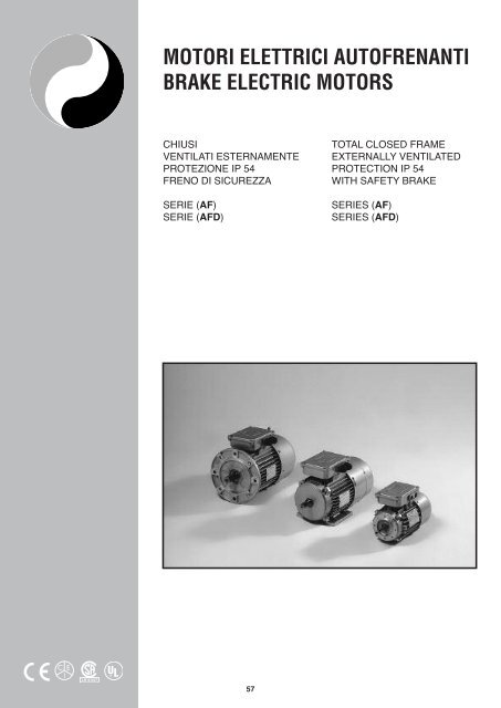
MOTORI ELETTRICI AUTOFRENANTI<br />
BRAKE ELECTRIC MOTORS<br />
CHIUSI<br />
VENTILATI ESTERNAMENTE<br />
PROTEZIONE IP 54<br />
FRENO DI SICUREZZA<br />
SERIE (AF)<br />
SERIE (AFD)<br />
TOTAL CLOSED FRAME<br />
EXTERNALLY VENTILATED<br />
PROTECTION IP 54<br />
WITH SAFETY BRAKE<br />
SERIES (AF)<br />
SERIES (AFD)<br />
LR 91167<br />
®<br />
57
B3 IM B3 IM1001<br />
DIMENSIONI FORMA COSTRUTTIVA<br />
OVERALL DIMENSIONS<br />
B3 (CEI 2-14) IM B3 (IEC 34-7 Code I) IM 1001 (IEC 34-7 Code II)<br />
FRAME H A B C R K V L L1 L2 G G1 G2 G3 U A1 B1 D E d<br />
56 56 90 71 36 95 6 104 228 248 208 158 100 118 110 78 108 90 9K6 20 M3<br />
63 63 100 80 40 95 7 134 243 266 220 167 102 127 125 80 120 100 11K6 23 M4<br />
71 71 112 90 45 95 10 156 273 303 243 185 113 145 138 91 135 109 14K6 30 M5<br />
80 80 125 100 50 115 11 176 315 355 275 210 129 161 155 103 154 125 19K6 40 M6<br />
90C 90 140 100 56 115 11 194 352 402 302 225 135 176 178 109 170 125 24K6 50 M8<br />
90L 90 140 125 56 115 11 220 378 428 328 225 135 176 178 109 170 150 24K6 50 M8<br />
100 100 160 140 63 115 12 246 423 483 363 247 146 198 195 120 192 166 28K6 60 M8<br />
112 112 190 140 70 112 14 267 466 526 406 267 154 222 223 131 220 175 28K6 60 M8<br />
132C 132 216 140 89 105 13 282 540 620 460 310 177 271 258 122 256 180 38K6 80 M10<br />
132M/L 132 216 178 89 105 13 399 579 659 499 310 177 271 258 122 256 218 38K6 80 M10<br />
160C 160 254 210 108 150 14 230 750 860 640 385 234 325 315 182 320 270 42K6 110 M12<br />
160M/L 160 254 254 108 150 14 230 800 906 686 385 234 325 315 182 320 310 42K6 110 M12<br />
X X1 K1 C1 P H1 h b t<br />
23 22 11 91 Pg11 8 3 3 10,2<br />
23 22 10 91 Pg11 8 4 4 12,5<br />
25 26 14 100 Pg11 9 5 5 16<br />
29 27 14 116 Pg13,5 10 6 6 21,5<br />
32 30 14 134 Pg16 11 7 8 27<br />
32 30 14 134 Pg16 11 7 8 27<br />
38 36 21 154 Pg16 12 7 8 31<br />
40 40 18 183 Pg16 15 7 8 31<br />
40 43 21 215 Pg21 18 8 10 41<br />
40 43 21 215 Pg21 18 8 10 41<br />
58 64 25 325 Pg21 23 8 12 45<br />
58 64 25 325 Pg21 23 8 12 45<br />
58
B5 IM B5 IM3001<br />
DIMENSIONI FORMA COSTRUTTIVA<br />
OVERALL DIMENSIONS<br />
B5 (CEI 2-14) IM B5 (IEC 34-7 Code I) IM 3001 (IEC 34-7 Code II)<br />
FRAME P N M Q R S V L L1 L2 G2 G3 U F<br />
56 120 80J6 100 2,5 95 7 106 230 250 210 100 110 78 7<br />
63 140 95J6 115 2,5 95 9 137 246 269 223 102 125 80 9,5<br />
71 160 110J6 130 2,5 95 11 161 278 308 248 113 138 91 9,5<br />
80 200 130J6 165 2,5 115 11 180 319 359 279 129 155 103 11,5<br />
90C 200 130J6 165 3,0 115 11 198 357 407 307 135 178 109 11,5<br />
90L 200 130J6 165 3,0 115 11 224 481 431 331 135 178 109 11,5<br />
100 250 180J6 215 3,5 115 14 251 430 490 370 146 195 120 14<br />
112 250 180J6 215 3,5 112 14 270 469 529 409 154 223 131 14<br />
132C 300 230J6 265 4,0 105 14 284 542 622 462 177 258 112 14<br />
132M/L 300 230J6 265 4,0 105 14 322 582 662 502 177 258 112 14<br />
160C 350 250J6 300 5,0 150 20 230 750 861 641 320 315 182 18<br />
160M/L 350 250J6 300 5,0 150 20 230 800 910 686 320 315 182 18<br />
D E d h b t<br />
9K6 20 M3 3 3 10,2<br />
11K6 23 M4 4 4 12,5<br />
14K6 30 M5 5 5 16<br />
19K6 40 M6 6 6 21,5<br />
24K6 50 M8 7 8 27<br />
24K6 50 M8 7 8 27<br />
28K6 60 M8 7 8 31<br />
28K6 60 M8 7 8 31<br />
38K6 80 M10 8 10 41<br />
38K6 80 M10 8 10 41<br />
42K6 110 M12 8 12 45<br />
42K6 110 M12 8 12 45<br />
59
B14 IM B14 IM3601<br />
DIMENSIONI FORMA COSTRUTTIVA<br />
OVERALL DIMENSIONS<br />
B14 (CEI 2-14) IM B14 (IEC 34-7 Code I) IM 3601 (IEC 34-7 Code II)<br />
FRAME P N M Q R V L L1 L2 G G1 G3 U F**<br />
56 80 50J6 65 2,5 95 106 230 250 210 155 100 110 78 M5<br />
63 90 60J6 75 2,5 95 137 246 269 223 163 102 125 80 M5<br />
71 105 70J6 85 2,5 95 161 278 308 248 182 113 138 91 M6<br />
80 120 80J6 100 2,5 115 180 319 359 279 207 129 155 103 M6<br />
90C 140 95J6 115 3,0 115 198 357 407 307 217 135 178 109 M8<br />
90L 140 95J6 115 3,0 115 224 481 431 331 217 135 178 109 M8<br />
100 160 110J6 130 3,5 115 251 430 490 370 240 146 195 120 M8<br />
112 160 110J6 130 3,5 112 270 469 529 409 260 154 223 131 M8<br />
132C 200 130J6 165 4,0 105 284 542 625 465 305 177 258 122 M10<br />
132M/L 200 130J6 165 4,0 105 322 582 662 502 304 177 258 122 M10<br />
160C 250 180J6 215 4,0 150 230 700 811 591 400 234 315 182 M12<br />
160M/L 250 180J6 215 4,0 150 230 750 856 636 400 234 315 182 M12<br />
D E d h b t<br />
9K6 20 M3 3 3 10,2<br />
11K6 23 M4 4 4 12,5<br />
14K6 30 M5 5 5 16<br />
19K6 40 M6 6 6 21,5<br />
24K6 50 M8 7 8 27<br />
24K6 50 M8 7 8 27<br />
28K6 60 M8 7 8 31<br />
28K6 60 M8 7 8 31<br />
38K6 80 M10 8 10 41<br />
38K6 80 M10 8 10 41<br />
42K6 110 M12 8 12 45<br />
42K6 110 M12 8 12 45<br />
60
2 POLI <strong>Autofrenanti</strong> Caratteristiche a Hz 50<br />
2 POLE Brake Motor Performance at Hz 50<br />
TIPO Power Giri In 230 In 400 Eff. % Cos ϕ Motor Torque Starting PD 2 Brake Peso<br />
TYPE kW rpm Amps Amps Cn Ca / Cn Cm / Cn Ia / In kg m 2 NM Kg<br />
AF 56 C2 0,09 2700 0,65 0,38 53 0,70 0,32 2,8 2,5 3,5 0,00010 1 3,1<br />
AF 56 S2 0,13 2710 1,00 0,57 54 0,72 0,46 2,6 3,1 3,5 0,00012 1 3,2<br />
AF 63 C2 0,18 2740 1,10 0,65 68 0,77 0,63 3,4 2,7 4,5 0,00071 2 4,3<br />
AF 63 S2 0,25 2755 1,80 1,10 67 0,68 0,90 3,3 2,4 4,0 0,00085 2 4,7<br />
AF 63 L2 0,37 2750 2,30 1,33 69 0,70 1,30 3,3 2,9 4,5 0,00090 2 5,0<br />
AF 71 C2 0,37 2800 2,00 1,16 72 0,75 1,26 2,4 2,0 4,5 0,00970 4 6,5<br />
AF 71 S2 0,55 2800 2,70 1,60 71 0,80 1,88 2,2 2,0 4,6 0,00136 4 7,0<br />
AF 80 C2 0,75 2820 3,30 1,90 78 0,80 2,60 2,2 2,1 5,0 0,00286 8 9,0<br />
AF 80 S2 1,10 2810 5,00 2,90 80 0,84 3,80 2,4 2,1 5,5 0,00361 8 10,5<br />
AF 90 SC2 1,50 2805 7,10 4,10 69 0,83 5,10 2,1 2,5 5,0 0,00644 16 15,0<br />
AF 90 LS2 2,20 2860 10,0 5,80 76 0,80 7,50 2,7 2,5 7,0 0,00843 16 17,5<br />
AF 100 SC2 3,00 2850 11,5 7,00 78 0,90 10,0 2,6 3,1 6,4 0,01345 32 22,0<br />
AF 100 LS2 4,00 2865 16,0 9,30 84 84 13,2 2,5 2,0 5,5 0,0143 32 25,0<br />
AF 112 MC2 4,00 2885 16,5 9,50 80 0,82 13,2 2,6 2,2 7,0 0,02566 60 35,0<br />
AF 112 LS2 5,50 2750 21,0 12,0 82 0,85 18,2 2,7 3,0 7,0 0,03122 60 38,5<br />
AF 132 MC2 5,50 2882 19,0 11,0 81 0,87 18,2 2,1 2,9 5,8 0,04300 60 40,0<br />
AF 132 LS2 7,50 2900 26,0 15,0 86 0,86 24,0 2,5 3,0 7,5 0,04788 60 52,0<br />
AF 132 LL2 9,50 2890 33,0 19,0 88 0,85 31,5 2,3 4,0 7,8 0,05211 60 59,0<br />
AF 160 SC2 11,0 2915 44,0 25,0 80 0,84 36,0 2,5 3,3 5,8 0,09243 100 88,0<br />
AF 160 LS2 15,0 2935 54,0 31,0 87 0,88 50,0 2,3 3,4 7,8 0,11000 100 105<br />
AF 160 LL2 18,5 2950 66,0 38,0 83 0,88 60,0 3,2 3,4 8,4 0,14210 100 113<br />
4 POLI <strong>Autofrenanti</strong> Caratteristiche a Hz 50<br />
4 POLE Brake Motor Performance at Hz 50<br />
TIPO Power Giri In 230 In 400 Eff. % Cos ϕ Motor Torque Starting PD 2 Brake Peso<br />
TYPE kW rpm Amps Amps Cn Ca / Cn Cm / Cn Ia / In kg m 2 NM Kg<br />
AF 56 C4 0,06 1345 0,35 0,20 56 0,67 0,43 2,1 2,0 2,7 0,00015 1 3,1<br />
AF 56 S4 0,09 1330 0,60 0,35 57 0,62 0,65 2,3 2,2 2,5 0,00023 1 3,3<br />
AF 63 C4 0,13 1280 0,80 0,50 58 0,70 0,97 1,9 1,6 2,3 0,00100 2 4,0<br />
AF 63 S4 0,18 1295 1,00 0,55 59 0,72 1,35 2,1 1,8 2,8 0,00140 2 4,7<br />
AF 63 L4 0,25 1300 1,10 0,60 64 0,73 1,80 1,9 1,6 3,1 0,00155 2 5,0<br />
AF 71 C4 0,25 1390 1,60 0,92 68 0,67 1,80 3,1 2,5 4,2 0,00253 4 6,3<br />
AF 71 S4 0,37 1370 2,30 1,30 64 0,70 2,60 2,5 2,0 3,3 0,00332 4 7,0<br />
AF 80 C4 0,55 1390 2,60 1,50 71 0,76 3,80 2,2 2,3 4,0 0,00541 8 9,5<br />
AF 80 S4 0,75 1380 4,20 2,50 70 0,73 5,20 2,3 2,2 4,1 0,00692 8 11,2<br />
AF 90 SC4 1,10 1400 5,50 3,20 74 0,75 7,70 2,2 2,3 3,9 0,01102 16 13,5<br />
AF 90 LS4 1,50 1400 7,00 4,00 77 0,73 10,5 2,4 2,6 4,5 0,01441 16 16,0<br />
AF 90 LL4 1,80 1390 8,80 5,10 75 0,72 12,5 2,0 2,5 4,1 0,01676 16 18,0<br />
AF 100 SC4 2,20 1396 11,0 6,40 76 0,81 15,0 1,8 2,4 4,1 0,03710 32 21,0<br />
AF 100 LS4 3,00 1400 13,0 7,50 78 0,80 21,0 1,8 2,4 4,0 0,04817 32 23,0<br />
AF 112 MS4 4,00 1450 16,5 9,50 80 0,81 26,5 2,1 2,9 5,3 0,07559 60 37,5<br />
AF 132 MC4 5,50 1440 22,0 13,0 82 0,83 36,5 2,2 3,0 6,0 0,11542 60 49,5<br />
AF 132 LS4 7,50 1445 28,0 16,0 83 0,85 50,0 2,2 3,2 6,6 0,12955 60 55,0<br />
AF 132 LL4 9,50 1415 37,0 21,0 81 0,89 61,5 2,6 3,4 7,7 0,15833 60 63,0<br />
AF 160 SC4 11,0 1450 43,0 24,5 80 0,84 73,0 1,7 2,8 6,5 0,23500 100 110<br />
AF 160 LS4 15,0 1455 57,0 33,0 81 0,83 99,0 1,9 2,8 7,3 0,30000 100 120<br />
AF 160 LL4 18,5 1460 60,0 35,0 82 0,84 121 2,1 3,0 7,0 0,44020 100 127<br />
Cn<br />
Ca / Cn<br />
Cm / Cn<br />
la / In<br />
PD 2<br />
Brake<br />
= Coppia nominale (Nm)<br />
= Coppia avviamento in rapporto alla coppia nominale<br />
= Coppia massima in rapporto alla coppia nominale<br />
= Corrente di spunto in rapporto alla corrente nominale<br />
= Inerzia all’albero motore con disco freno montato<br />
= Coppia nominale del freno montato in configurazione standard (Nm)<br />
Cn = Nominal torque (Nm)<br />
Ca / Cn = Starting torque by nominal torque ratio<br />
Cm / Cn = Maximum motor torque by nominal torque ratio<br />
la / In = Starting current by nominal current ratio<br />
PD 2 = Motor shaft inertia w<strong>it</strong>h brake assembled<br />
Brake = Brake nominal torque (Nm)<br />
61
6 POLI <strong>Autofrenanti</strong> Caratteristiche a Hz 50<br />
6 POLE Brake Motor Performance at Hz 50<br />
TIPO Power Giri In 230 In 400 Eff. % Cos ϕ Motor Torque Starting PD 2 Brake Peso<br />
TYPE kW rpm Amps Amps Cn Ca / Cn Cm / Cn Ia / In kg m 2 NM Kg<br />
AF 63 C6 0,09 835 0,75 0,50 52 0,62 1,03 1,4 1,3 1,9 0,00071 2 4,3<br />
AF 71 C6 0,18 865 1,30 0,75 66 0,70 1,98 1,9 1,6 2,3 0,00970 4 6,5<br />
AF 71 S6 0,25 875 1,50 0,90 63 0,70 2,80 1,8 2,4 2,2 0,00136 4 7,0<br />
AF 80 C6 0,37 900 2,50 1,50 60 0,73 4,00 1,5 1,9 2,7 0,00286 8 9,0<br />
AF 80 S6 0,55 926 3,50 2,00 63 0,64 5,70 2,1 2,3 3,3 0,00361 8 10,5<br />
AF 90 SC6 0,75 895 3,70 2,10 66 0,78 8,00 1,8 1,9 3,4 0,00644 16 15,0<br />
AF 90 LS6 1,10 900 5,30 3,10 70 0,75 12,0 1,7 2,0 3,4 0,00843 16 17,5<br />
AF 100 SC6 1,50 925 7,50 4,50 71 0,74 15,5 1,8 2,1 3,6 0,01345 32 22,0<br />
AF 100 LS6 1,80 940 10,0 5,80 68 0,72 18,5 2,1 2,3 4,0 0,0143 32 25,0<br />
AF 112 MC6 2,20 910 10,5 6,00 75 0,77 23,0 1,4 1,8 4,0 0,02566 60 35,0<br />
AF 112 LS6 3,00 916 12,0 7,00 75 0,82 31,0 1,5 2,2 4,5 0,03122 60 38,5<br />
AF 132 MC6 3,00 950 13,5 7,80 71 0,77 30,0 1,3 2,0 3,5 0,04300 60 40,0<br />
AF 132 LS6 4,00 950 18,0 10,5 75 0,77 42,0 1,3 2,2 4,3 0,04788 60 52,0<br />
AF 132 LL6 5,50 950 23,0 13,6 77 0,78 55,0 1,5 2,3 4,0 0,05211 60 59,0<br />
AF 160 SC6 7,50 960 28,0 16,5 80 0,83 75,0 1,2 2,4 3,0 0,09243 100 105<br />
AF 160 LS6 11,0 965 42,0 25,0 80 0,83 110 1,2 2,5 3,5 0,11000 100 118<br />
AF 160 LL6 18,5 900 52,0 30,0 83 0,82 148 1,7 2,5 4,8 0,14210 100 135<br />
8 POLI <strong>Autofrenanti</strong> Caratteristiche a Hz 50<br />
8 POLE Brake Motor Performance at Hz 50<br />
TIPO Power Giri In 230 In 400 Eff. % Cos ϕ Motor Torque Starting PD 2 Brake Peso<br />
TYPE kW rpm Amps Amps Cn Ca / Cn Cm / Cn Ia / In kg m 2 NM Kg<br />
AF 71 C8 0,15 605 1,25 0,75 50 0,60 2,45 1,7 1,7 1,8 0,00253 4 7,3<br />
AF 80 C8 0,25 680 2,00 1,10 56 0,62 3,50 1,5 1,7 2,4 0,00541 8 9,5<br />
AF 90 SC8 0,37 695 2,80 1,60 54 0,61 5,10 1,6 2,0 2,7 0,01102 16 13,5<br />
AF 90 LS8 0,55 685 3,80 2,20 58 0,65 7,70 1,7 1,9 2,8 0,01441 16 16,0<br />
AF 100 SC8 0,75 695 4,00 2,30 64 0,72 10,5 1,4 1,7 2,9 0,03710 32 21,0<br />
AF 100 LS8 1,10 695 7,00 3,90 62 0,68 15,5 1,8 1,9 3,0 0,04817 32 23,0<br />
AF 112 MC8 1,50 690 8,00 4,50 68 0,71 21,0 1,3 2,0 3,0 0,07559 60 37,5<br />
AF 132 MC8 2,20 700 11,0 6,50 69 0,73 30,0 1,5 2,0 3,0 0,11542 60 49,5<br />
AF 132 LS8 3,00 710 15,0 8,70 70 0,72 40,5 1,5 2,1 3,2 0,12955 60 55,0<br />
AF 160 SC8 4,00 715 18,0 10,5 77 0,73 54,0 1,4 2,2 3,0 0,23500 100 85,5<br />
AF 160 LS8 5,50 720 23,0 13,5 81 0,76 73,0 1,4 2,6 3,6 0,30000 100 98,0<br />
AF 160 LL8 7,50 700 30,0 17,5 82 0,77 100 1,3 2,8 3,6 0,44020 100 118<br />
12 POLI <strong>Autofrenanti</strong> Caratteristiche a Hz 50<br />
12 POLE Brake Motor Performance at Hz 50<br />
TIPO Power Giri In 230 In 400 Eff. % Cos ϕ Motor Torque Starting PD 2 Brake Peso<br />
TYPE kW rpm Amps Amps Cn Ca / Cn Cm / Cn Ia / In kg m 2 NM Kg<br />
AF 80 S12 0,11 400 1,85 1,10 45 0,53 2,11 1,1 1,8 2,2 0,0069 8 12,0<br />
AF 90 LS12 0,25 400 3,30 1,90 50 0,63 5,00 1,3 2,0 2,5 0,0140 16 18,0<br />
AF 100 LS12 0,55 420 3,70 2,20 52 0,64 10,6 1,4 2,2 2,3 0,0482 32 25,0<br />
AF 112 MS12 0,75 430 5,50 3,20 51 0,63 14,5 1,7 2,3 2,5 0,0741 60 38,5<br />
AF 132 MC12 1,10 450 6,80 4,00 53 0,65 21,5 1,6 2,2 2,7 0,1218 60 55,7<br />
AF 132 LS12 1,50 455 9,50 5,50 54 0,64 28,5 1,5 2,4 3,0 0,1683 60 61,3<br />
AF 160 SC12 2,20 450 14,5 8,50 52 0,62 42,5 1,6 2,5 2,9 0,2455 100 83,0<br />
AF 160 LS12 3,00 460 16,5 9,50 53 0,66 56,5 1,7 2,8 3,6 0,3545 100 105<br />
62
2/4 POLI <strong>Autofrenanti</strong> Avvolgimento unico, Tensione unica Caratteristiche a Hz 50<br />
2/4 POLE Brake Motor One winding, One voltage Performance at Hz 50<br />
TIPO Power CURRENT 400 V. SPEED (RPM) Cn (Nm) Ca / Cn Starting Amps PD 2 Brake Peso<br />
TYPE kW kW Amps Amps High Low High Low High Low High Low kg m 2 NM Kg<br />
AFD 63 S 2/4 0,30 0,20 0,92 0,75 2760 1370 1,10 1,40 1,9 1,9 3,4 3,0 0,001 2 5,0<br />
AFD 71 S 2/4 0,45 0,30 1,50 1,10 2765 1410 1,50 2,00 2,9 2,9 3,6 3,7 0,003 4 8,2<br />
AFD 80 C 2/4 0,60 0,45 1,80 1,40 2735 1400 2,10 3,00 2,2 1,9 3,8 3,6 0,006 8 9,5<br />
AFD 80S 2/4 0,75 0,55 2,25 1,80 2820 1425 2,50 3,80 2,9 2,5 4,6 4,2 0,008 8 13,4<br />
AFD 90 LC 2/4 1,55 1,18 3,60 3,10 2815 1415 4,80 8,10 3,2 2,7 5,9 5,0 0,014 16 18,0<br />
AFD 90 LS 2/4 1,92 1,40 4,40 3,80 2800 1400 6,60 9,70 2,8 2,2 5,6 4,1 0,015 16 19,8<br />
AFD 100 LC 2/4 2,50 1,84 5,80 4,30 2840 1425 8,60 12,5 2,3 1,9 5,2 5,1 0,037 32 23,5<br />
AFD 100 LS 2/4 3,30 2,58 8,00 6,30 2835 1400 11,4 17,9 2,1 1,8 5,2 5,8 0,048 32 26,0<br />
AFD 112 MC 2/4 4,42 3,31 10,0 8,00 2905 1450 15,0 22,2 1,6 1,6 5,6 4,1 0,075 60 40,0<br />
AFD 132 MS 2/4 5,52 4,42 12,0 12,0 2910 1450 18,6 29,7 2,7 2,2 7,2 4,4 0,110 60 48,0<br />
AFD 132 ML 2/4 8,10 6,60 17,0 16,0 2920 1455 27,2 44,7 2,2 1,7 7,6 4,5 0,130 60 55,0<br />
AFD 160 MC 2/4 11,0 8,80 22,5 22,0 2945 1465 36,9 59,4 2,3 2,2 7,3 4,6 0,240 100 100<br />
AFD 160 LS 2/4 14,7 12,5 31,0 28,5 2935 1460 48,7 83,7 2,3 2,1 7,4 4,8 0,300 100 116<br />
4/8 POLI <strong>Autofrenanti</strong> Avvolgimento unico, Tensione unica Caratteristiche a Hz 50<br />
4/8 POLE Brake Motor One winding, One voltage Performance at Hz 50<br />
TIPO Power CURRENT 400 V. SPEED (RPM) Cn (Nm) Ca / Cn Starting Amps PD 2 Brake Peso<br />
TYPE kW kW Amps Amps High Low High Low High Low High Low kg m 2 NM Kg<br />
AFD 71 S 4/8 0,26 0,13 0,80 0,60 1355 660 1,86 1,95 1,8 1,8 2,8 2,1 0,004 4 8,2<br />
AFD 80 C 4/8 0,37 0,18 1,00 0,90 1400 705 2,57 2,54 1,6 1,6 3,7 2,4 0,008 8 9,5<br />
AFD 80 S 4/8 0,51 0,26 1,50 1,20 1390 700 3,57 3,61 1,6 1,6 3,4 2,2 0,010 8 13,4<br />
AFD 90 SC 4/8 0,74 0,37 2,10 1,80 1385 695 5,20 5,18 1,8 1,9 4,0 2,8 0,014 16 18,0<br />
AFD 90 LS 4/8 0,96 0,51 2,40 2,20 1410 690 6,65 7,30 2,2 2,3 5,2 3,4 0,015 16 19,8<br />
AFD 100 LC 4/8 1,40 0,66 3,30 3,40 1415 715 9,66 9,30 1,6 2,1 4,3 2,8 0,037 32 23,5<br />
AFD 112 MC 4/8 1,77 1,03 4,20 4,00 1440 707 12,0 14,0 2,2 2,3 6,3 3,7 0,048 32 26,0<br />
AFD 112 MC 4/8 2,20 1,30 5,20 4,60 1435 705 15,0 18,2 1,8 1,4 4,9 2,7 0,075 60 40,0<br />
AFD 132 MS 4/8 3,70 2,10 9,60 7,20 1440 710 25,1 28,8 1,4 1,3 4,1 2,7 0,110 60 48,0<br />
AFD 132 ML 4/8 4,80 2,60 11,7 8,40 1455 725 32,2 3,49 1,6 1,5 5,1 3,6 0,130 60 55,0<br />
AFD 160 MC 4/8 6,30 4,00 13,5 12,0 1430 715 42,9 54,5 1,3 1,2 4,7 3,6 0,365 100 100<br />
AFD 160 LS 4/8 7,40 4,80 22,0 16,5 1425 720 50,5 64,9 1,3 1,6 4,3 3,7 0,443 100 116<br />
AFD 160 LL 4/8 10,3 5,90 23,0 19,0 1450 720 69,1 79,8 1,7 1,7 4,8 3,3 0,525 100 120<br />
6/12 POLI <strong>Autofrenanti</strong> Avvolgimento unico, Tensione unica Caratteristiche a Hz 50<br />
6/12 POLE Brake Motor One winding, One voltage Performance at Hz 50<br />
TIPO Power CURRENT 400 V. SPEED (RPM) Cn (Nm) Ca / Cn Starting Amps PD 2 Brake Peso<br />
TYPE kW kW Amps Amps High Low High Low High Low High Low kg m 2 NM Kg<br />
AFD 80 S 6/12 0,22 0,07 1,50 0,90 860 420 2,50 1,25 1,7 2,1 3,2 1,5 0,015 8 11,0<br />
AFD 90 LS 6/12 0,37 0,09 2,05 1,10 920 420 4,00 1,85 1,8 2,7 3,4 1,8 0,020 16 18,5<br />
AFD 100 LS 6/12 0,55 0,11 2,30 1,45 960 440 5,70 2,30 1,9 2,9 4,8 2,0 0,050 32 26,0<br />
AFD 112 MS 6/12 0,75 0,20 3,50 1,80 960 460 7,30 4,60 2,1 3,0 4,6 1,9 0,110 60 38,0<br />
AFD 132 MC 6/12 1,10 0,35 6,80 2,20 965 470 10,0 7,13 2,0 3,2 4,5 1,7 0,155 60 55,1<br />
AFD 132 ML 6/12 1,50 0,50 8,60 3,20 950 460 15,6 10,4 2,1 3,1 4,4 1,8 0,170 60 64,2<br />
AFD 160 MC 6/12 2,20 0,60 12,0 4,00 970 465 22,1 12,5 2,2 3,3 4,3 1,6 0,480 100 96,0<br />
AFD 160 ML 6/12 3,00 0,75 14,0 5,50 975 470 30,0 15,3 2,4 3,2 4,2 1,5 0,600 100 100<br />
63
4/6 POLI <strong>Autofrenanti</strong> Avvolgimento doppio, Tensione unica Caratteristiche a Hz 50<br />
4/6 POLE Brake Motor Double winding, One voltage Performance at Hz 50<br />
TIPO Power CURRENT 400 V. SPEED (RPM) Cn (Nm) Ca / Cn Starting Amps PD 2 Brake Peso<br />
TYPE kW kW Amps Amps High Low High Low High Low High Low kg m 2 NM Kg<br />
AFD 71 S 4/6 0,25 0,18 0,80 0,70 1370 890 1,85 2,00 1,5 1,7 3,1 2,4 0,003 4 8,2<br />
AFD 80 C 4/6 0,37 0,26 1,20 1,10 1380 900 2,61 2,81 1,7 1,4 3,6 2,6 0,006 8 9,5<br />
AFD 80 S 4/6 0,55 0,37 1,60 1,30 1400 920 3,83 3,91 1,7 1,3 3,9 2,8 0,008 8 13,4<br />
AFD 90 SC 4/6 0,89 0,59 2,30 2,30 1400 950 6,25 6,00 2,0 1,6 4,1 3,6 0,014 16 18,0<br />
AFD 90 LS 4/6 1,00 0,65 3,40 2,60 1460 925 7,00 7,00 3,0 1,5 5,3 1,8 0,015 16 19,8<br />
AFD 100 LC 4/6 1,10 0,75 3,60 2,90 1460 935 7,50 8,00 3,0 1,5 5,6 1,8 0,037 32 23,5<br />
AFD 100 LS 4/6 1,47 0,89 4,30 3,20 1445 920 10,0 9,50 2,6 1,7 5,0 2,6 0,048 32 26,0<br />
AFD 112 MC 4/6 2,50 1,80 5,00 4,50 1440 930 12,5 13,5 1,8 1,5 5,9 3,8 0,075 60 40,0<br />
AFD 112 MS 4/6 3,50 2,50 6,50 5,50 1420 920 17,5 19,0 2,0 1,4 6,6 5,0 0,090 60 47,2<br />
AFD 132 MS 4/6 4,00 2,60 9,50 7,50 1470 965 27,0 26,5 2,1 1,5 8,0 5,6 0,110 60 48,0<br />
AFD 132 ML 4/6 4,50 3,00 10,5 9,00 1460 960 29,0 29,3 2,5 1,3 7,7 5,4 0,130 60 55,0<br />
AFD 160 MC 4/6 6,60 4,40 14,5 10,0 1460 950 43,5 44,5 2,3 1,4 7,3 4,6 0,240 100 100<br />
AFD 160 LS 4/6 8,80 5,90 17,5 12,5 1450 950 58,0 59,5 2,3 1,3 7,4 4,8 0,300 100 116<br />
6/8 POLI <strong>Autofrenanti</strong> Avvolgimento doppio, Tensione unica Caratteristiche a Hz 50<br />
6/8 POLE Brake Motor Double winding, One voltage Performance at Hz 50<br />
TIPO Power CURRENT 400 V. SPEED (RPM) Cn (Nm) Ca / Cn Starting Amps PD 2 Brake Peso<br />
TYPE kW kW Amps Amps High Low High Low High Low High Low kg m 2 NM Kg<br />
AFD 71 S 6/8 0,22 0,11 0,87 0,58 860 650 2,50 1,65 1,8 2,0 2,1 1,7 0,005 4 8,5<br />
AFD 80 S 6/8 0,37 0,18 1,40 1,00 920 700 4,00 3,60 1,4 1,7 2,7 1,8 0,015 8 11,0<br />
AFD 90 LS 6/8 0,55 0,30 2,00 1,80 960 720 5,50 4,00 2,1 1,9 4,4 2,9 0,020 16 18,5<br />
AFD 100 LS 6/8 0,75 0,50 2,30 2,10 960 710 7,80 6,00 1,9 1,9 4,1 3,0 0,030 32 26,0<br />
AFD112 MC 6/8 0,96 0,66 3,00 2,30 965 710 9,79 9,10 1,4 1,7 4,5 3,8 0,055 60 35,0<br />
AFD 112 MS 6/8 1,50 0,75 4,60 3,10 950 715 15,6 10,1 2,1 2,2 4,6 3,3 0,070 60 38,0<br />
AFD 132 MC 6/8 2,20 1,25 7,00 5,50 970 720 22,1 16,9 1,4 1,7 4,5 3,7 0,155 60 55,1<br />
AFD 132 ML 6/8 3,00 1,75 8,50 6,00 975 720 30,0 23,0 1,5 1,2 5,4 3,6 0,170 60 64,2<br />
AFD 160 MC 6/8 4,80 2,60 12,0 7,80 960 720 48,0 35,0 1,7 1,5 4,7 2,8 0,480 100 96,0<br />
AFD 160 ML 6/8 5,90 3,30 14,0 10,0 965 715 60,0 45,0 1,4 1,5 4,0 3,3 0,600 100 100<br />
2/12 POLI <strong>Autofrenanti</strong> Avvolgimento doppio, Tensione unica Caratteristiche a Hz 50<br />
2/12 POLE Brake Motor Double winding, One voltage Performance at Hz 50<br />
TIPO Power CURRENT 400 V. SPEED (RPM) Cn (Nm) Ca / Cn Starting Amps PD 2 Brake Peso<br />
TYPE kW kW Amps Amps High Low High Low High Low High Low kg m 2 NM Kg<br />
AFD 80 S 2/12 0,37 0,07 1,10 0,90 2780 420 1,40 1,25 1,7 2,1 3,2 1,5 0,015 8 11,0<br />
AFD 90 LS 2/12 0,55 0,09 1,55 1,10 2850 420 1,82 1,85 1,8 2,7 3,4 1,8 0,020 16 18,5<br />
AFD 100 LS 2/12 0,75 0,11 2,00 1,45 2850 440 2,35 2,30 1,9 2,9 4,8 2,0 0,050 32 26,0<br />
AFD 112 MC 2/12 1,10 0,15 2,90 1,50 2850 450 3,70 3,20 1,9 3,0 4,4 1,8 0,090 60 35,0<br />
AFD 112 MS 2/12 1,50 0,20 3,50 1,80 2860 460 5,00 4,60 2,1 3,0 4,6 1,9 0,110 60 38,0<br />
AFD 132 MC 2/12 2,20 0,35 4,50 2,20 2850 470 7,40 7,13 2,0 3,2 4,5 1,7 0,155 60 55,1<br />
AFD 132 ML 2/12 2,50 0,50 5,60 3,20 2860 460 8,36 10,4 2,1 3,1 4,4 1,8 0,170 60 64,2<br />
AFD 160 MC 2/12 3,00 0,60 7,00 4,00 2860 465 10,0 12,5 2,2 3,3 4,3 1,6 0,480 100 96,0<br />
AFD 160 ML 2/12 3,50 0,75 8,90 5,50 2870 470 11,5 15,3 2,4 3,2 4,2 1,5 0,600 100 100<br />
Cn<br />
Ca / Cn<br />
Cm / Cn<br />
la / In<br />
PD 2<br />
Brake<br />
High<br />
Low<br />
= Coppia nominale (Nm)<br />
= Coppia avviamento in rapporto alla coppia nominale<br />
= Coppia massima in rapporto alla coppia nominale<br />
= Corrente di spunto in rapporto alla corrente nominale<br />
= Inerzia all’albero motore con disco freno montato<br />
= Coppia nominale del freno montato in configurazione standard (Nm)<br />
= Dati rifer<strong>it</strong>i all’alta veloc<strong>it</strong>à del motore<br />
= Dati rifer<strong>it</strong>i alla bassa veloc<strong>it</strong>à del motore<br />
64<br />
Cn = Nominal torque (Nm)<br />
Ca / Cn = Starting torque by nominal torque ratio<br />
Cm / Cn = Maximum motor torque by nominal torque ratio<br />
la / In = Starting current by nominal current ratio<br />
PD 2 = Motor shaft inertia w<strong>it</strong>h brake assembled<br />
Brake = Brake nominal torque (Nm)<br />
High = Technical data of High speed motor<br />
Low = Technical data of Low speed motor
2/6 POLI <strong>Autofrenanti</strong> Avvolgimento doppio, Tensione unica Caratteristiche a Hz 50<br />
2/6 POLE Brake Motor Double winding, One voltage Performance at Hz 50<br />
TIPO Power CURRENT 400 V. SPEED (RPM) Cn (Nm) Ca / Cn Starting Amps PD 2 Brake Peso<br />
TYPE kW kW Amps Amps High Low High Low High Low High Low kg m 2 NM Kg<br />
AFD 71 S 2/6 0,25 0,15 0,85 0,85 2800 760 0,90 1,32 1,9 0,9 3,2 1,4 0,003 4 8,2<br />
AFD 80 C 2/6 0,55 0,20 1,40 1,20 2800 770 1,75 2,40 2,0 1,0 3,8 1,5 0,006 8 9,5<br />
AFD 80 S 2/6 0,75 0,30 1,90 1,60 2830 790 2,40 3,40 2,2 1,0 4,1 1,6 0,008 8 13,4<br />
AFD 90 SC 2/6 1,00 0,48 2,40 1,85 2840 830 3,40 4,80 2,1 1,1 4,4 1,8 0,014 16 18,0<br />
AFD 90 LS 2/6 1,35 0,65 3,10 2,30 2860 850 4,42 7,21 2,3 1,3 5,1 1,9 0,015 16 19,8<br />
AFD 100 LC 2/6 1,80 0,90 4,20 2,90 2880 900 5,62 9,82 2,2 1,2 5,6 1,8 0,037 32 23,5<br />
AFD 100 LS 2/6 2,20 1,10 4,90 3,30 2890 900 7,22 11,5 2,3 1,3 6,4 2,0 0,048 32 26,0<br />
AFD 112 MC 2/6 3,00 1,50 6,80 4,60 2900 810 9,30 15,3 2,4 1,4 6,7 2,1 0,075 60 40,0<br />
AFD 132 MS 2/6 5,90 2,60 14,0 7,65 2930 920 19,8 25,8 2,8 1,4 7,0 4,0 0,110 60 48,0<br />
AFD 132 ML 2/6 6,30 3,00 15,5 8,00 2900 960 20,6 29,3 2,5 1,3 6,8 4,0 0,130 60 55,0<br />
AFD 160 MC 2/6 9,20 3,30 19,5 9,50 2900 970 30,5 32,7 2,3 1,4 7,3 4,6 0,240 100 100<br />
AFD 160 LS 2/6 12,5 4,50 25,0 11,0 2920 970 41,0 43,5 2,3 1,3 7,4 4,8 0,300 100 116<br />
2/8 POLI <strong>Autofrenanti</strong> Avvolgimento doppio, Tensione unica Caratteristiche a Hz 50<br />
2/8 POLE Brake Motor Double winding, One voltage Performance at Hz 50<br />
TIPO Power CURRENT 400 V. SPEED (RPM) Cn (Nm) Ca / Cn Starting Amps PD 2 Brake Peso<br />
TYPE kW kW Amps Amps High Low High Low High Low High Low kg m 2 NM Kg<br />
AFD 71 S 2/8 0,30 0,09 1,10 0,80 2790 675 0,86 1,16 1,1 1,8 3,5 2,2 0,004 4 8,2<br />
AFD 80 C 2/8 0,37 0,11 1,25 0,68 2830 750 1,27 1,55 2,5 1,7 4,3 2,4 0,008 8 9,5<br />
AFD 80 S 2/8 0,55 0,15 1,50 0,90 2875 700 1,90 1,53 2,0 2,3 5,4 2,0 0,010 8 13,4<br />
AFD 90 SC 2/8 0,74 0,18 2,50 1,20 2842 716 2,58 2,50 3,0 2,3 4,7 2,9 0,014 16 18,0<br />
AFD 90 LS 2/8 1,10 0,29 3,30 1,50 2865 715 3,80 3,10 2,4 2,0 5,5 2,9 0,015 16 19,8<br />
AFD 100 LC 2/8 1,47 0,37 3,50 2,00 2885 700 5,00 5,00 1,9 1,7 5,7 2,1 0,037 32 23,5<br />
AFD 100 LS 2/8 1,84 0,44 4,30 2,20 2840 683 6,50 6,16 1,4 0,8 4,6 1,9 0,048 32 26,0<br />
AFD 112 MC 2/8 1,84 0,50 5,00 2,50 2905 692 6,22 6,91 2,9 1,2 6,7 2,7 0,075 60 30,0<br />
AFD 112 MS 2/8 2,06 0,75 4,90 2,10 2800 700 7,16 10,0 2,9 1,3 5,8 3,2 0,090 60 38,0<br />
AFD 112 ML 2/8 3,00 1,00 6,50 2,50 2830 710 7,50 13,5 2,4 1,6 6,0 3,6 0,100 60 45,0<br />
AFD 132 MC 2/8 3,70 1,10 7,50 3,00 2900 720 12,1 14,6 2,6 1,5 6,8 3,6 0,155 60 67,6<br />
AFD 132 ML 2/8 5,00 1,25 11,0 3,60 2900 710 17,1 16,8 2,4 1,4 7,0 3,7 0,130 60 76,5<br />
AFD 132 LL 2/8 6,30 1,50 15,0 5,00 2880 700 20,7 20,1 2,3 1,5 7,0 3,9 0,160 60 84,3<br />
AFD 160 MC 2/8 9,20 2,20 18,5 6,80 2870 698 30,6 30,2 2,5 1,7 7,5 4,5 0,240 100 122<br />
AFD 160 ML 2/8 12,5 3,00 25,0 9,50 2910 715 41,0 39,5 2,5 1,6 7,7 4,4 0,300 100 145<br />
Two separate windings for two speed motors:<br />
Number of pole: 2/6, 2/8, 4/6, 6/8<br />
Synchronous speed at 50 Hz: 3000/1000, 3000/750, 1500/1000, 1000/750.<br />
Dahlander system for two speed motors, constant torque:<br />
Number of pole: 2/4, 4/8<br />
Synchronous speed at 50 Hz: 3000/1500, 1500/750.<br />
65
POWERBOX<br />
POWERBOX<br />
Informazioni generali<br />
La KEB Powerbox è stata studiata per migliorare le caratteristiche<br />
di commutazione degli elettromagneti. Nel caso<br />
di collegamento alla corrente AC (corrente continua) essa<br />
sost<strong>it</strong>uisce i raddrizzatori a semi-onda o a piena-onda.<br />
General<br />
The KEB Powerbox was developed to improve the sw<strong>it</strong>ching<br />
characteristic of electromagnets. In case of connection<br />
to AC voltage <strong>it</strong> replaces half-wave or full-wave rectifiers<br />
U vmax<br />
Corrente massima di spegnimento<br />
Max. turn-off voltage<br />
U t<br />
U B<br />
t p<br />
Corrente di ecc<strong>it</strong>azione<br />
Exc<strong>it</strong>ation voltage<br />
Corrente di funzionamento<br />
Operating voltage<br />
Tempo di sovra-ecc<strong>it</strong>azione<br />
Overexc<strong>it</strong>ation time<br />
Vantaggi<br />
In relazione alla corrente di alimentazione e della bobina<br />
si hanno i seguenti vantaggi:<br />
Corrente in entrata 230 V AC Bobina 105 V DC<br />
• Il tempo di disconnessione (disinnesto) é più breve rispetto<br />
all’ecc<strong>it</strong>azione normale e alla connessione a raddrizzatori<br />
a semi-onda.<br />
• La resistenza all’usura è raddoppiata (usura fino alla<br />
regolazione del traferro).<br />
Corrente in entrata 230 V AC Bobina 205 V DC<br />
• Il tempo di connessione é più breve (-30%) dovuto alla<br />
corrente di mantenimento piccola.<br />
• La corrente di mantenimento di 105 V è sufficiente a<br />
mantenere sicura l’armatura. La potenza viene ridotta<br />
al 25%, riducendo così il riscaldamento.<br />
Corrente in entrata 180 - 264 V AC Bobina 130 V DC<br />
• Insensibile agli sbalzi di corrente provenienti dall’alimentazione<br />
principale, garantisce comunque il funzionamento<br />
sicuro del freno. In relazione alla corrente<br />
attuale di alimentazione si hanno gli ulteriori vantaggi<br />
elencati sopra.<br />
Advantages<br />
In dependence on supply and coil voltage following advantages<br />
are the result:<br />
230 V AC Input Voltage 105 V DC Coil<br />
• short release time compared to normal exc<strong>it</strong>ation and<br />
connection to half-wave rectifiers<br />
• wear capac<strong>it</strong>y is doubled (wear until adjustment of the<br />
air gap)<br />
230 V AC Input Voltage 205 V DC Coil<br />
• short engaging time (-30%) due to small holding voltage<br />
•<br />
the holding voltage of 105 V is sufficient to retain the<br />
armature. The power is reduced to 25% thus causing<br />
less heating<br />
180 - 264 V AC Input Voltage 130 V DC Coil<br />
• insens<strong>it</strong>ive to voltage fluctuations from the mains, yet<br />
still providing safe functioning of the brake. In dependence<br />
on the actual mains voltage <strong>it</strong> results in the<br />
a d d i -<br />
tional advantages listed above.<br />
Tempo di disconnessione e traferro<br />
con la Powerbox<br />
Traferro<br />
X max<br />
con la Powerbox<br />
X max<br />
senza Powerbox<br />
Tempo<br />
di disconnessione<br />
t 2<br />
con la Powerbox<br />
t 2<br />
senza Powerbox<br />
Release time and airgap w<strong>it</strong>h Powerbox<br />
Airgap<br />
Release time<br />
X max<br />
w<strong>it</strong>h Powerbox<br />
X max<br />
w<strong>it</strong>hout Powerbox<br />
t 2<br />
w<strong>it</strong>h Powerbox<br />
t 2<br />
w<strong>it</strong>hout Powerbox<br />
66
GENERALITÀ FRENI<br />
I freni usati da BER-MAR sono freni elettromagnetici a<br />
molla per funzionamento a secco a doppia superficie frenante.<br />
L’esperienza acquis<strong>it</strong>a in molti anni di collaborazione<br />
con le varie industrie, ci permette di sostenere che i<br />
freni da noi adottati rispondono agli ultimi standard tecnologici.<br />
L’ottima qual<strong>it</strong>à dei materiali, l’accurata costruzione con<br />
macchine moderne, la produzione senza compromessi ed<br />
i controlli di qual<strong>it</strong>à sono garanzia di credibil<strong>it</strong>à e sicurezza.<br />
Questo catalogo contiene due serie differenti di freni completi<br />
di accessori che sono sol<strong>it</strong>amente richiesti (leva di<br />
sblocco, flangia intermedia, disco frizione, anello di protezione<br />
etc.). Qui di segu<strong>it</strong>o ricordiamo la qual<strong>it</strong>à dei freni di<br />
sicurezza a molla e cioé: maggiore sicurezza di frenata<br />
delle masse rotanti, precisione e posizionamento dell’albero<br />
a fine ciclo. E’ possibile produrre su disegno del<br />
cliente motori con freni speciali per soddisfare al meglio le<br />
singole esigenze.<br />
GENERAL BRAKE<br />
The brake used on BER-MAR motors are electromagnetic-actuated<br />
double- sided spring applied brakes for dry<br />
operation. By reason of our experience which we have<br />
gained during the many years of cooperation w<strong>it</strong>h the<br />
industry the brakes meet the latest technological standard.<br />
The high-grade material, the high-accuracy processing<br />
through modern machines and the uncompromising production<br />
and performance checks are guarantor for reliabil<strong>it</strong>y<br />
and safety.<br />
This catalogue contains two finely differentiated series<br />
w<strong>it</strong>h the accessories that are commonly required (hand<br />
release, intermediate flange, friction disc, protection ring<br />
etc.). Thus a qual<strong>it</strong>y fail safe brake for braking rotating<br />
masses or for holding shafts in a precise pos<strong>it</strong>ion is available<br />
for a wide range of applications. In many cases only<br />
a tailor-made brake can fulfill the requirements to an optimum.<br />
Please contact our indoor and outdoor experts.<br />
Caratteristiche di costruzione FRENI<br />
• Il ferodo senza amianto e con una speciale anima in<br />
acciaio interna garantisce una frenata sicura anche in<br />
condizioni di massima usura;<br />
• Magnete e indotto brevettato assicurano tempi brevi di<br />
intervento anche in presenza di traferro elevato;<br />
• Coppia di frenatura regolabile dal 100% al 50% di M2n<br />
o dal 60% al 15% di M2n;<br />
• La regolazione del traferro (brevettata) si effettua senza<br />
dover smontare il freno;<br />
• Cavo di collegamento solido e robusto;<br />
• Tempo operativo illim<strong>it</strong>ato;<br />
• Classe di isolamento B;<br />
• Approvato a norme CSA.<br />
BRAKE Construction Features<br />
• Asbestos-free friction linings, that warrant a safe<br />
braking, even under extreme cond<strong>it</strong>ions, through a<br />
pressed-in sheet steel ring;<br />
• Patented magnet/armature geometry ensures small<br />
sw<strong>it</strong>ching times and large in-process air gaps;<br />
• Serial braking torque adjustment from 1.0...0.5 · M2n;<br />
on request 0.6...0.15 M2n;<br />
• Patented clearance adjustment that result in easy<br />
• Mounting and readjustment after wear w<strong>it</strong>hout dismantling;<br />
• Stable, rugged connecting cable;<br />
• Unlim<strong>it</strong>ed operating time;<br />
• Insulation class B;<br />
• CSA approved.<br />
67
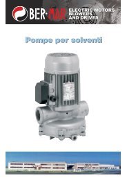
1 V<strong>it</strong>i di fissaggio<br />
DIN 912 u. 6912<br />
Machine screw<br />
2 Magnete<br />
Magnet<br />
3 Indotto<br />
Armature<br />
4 Anello di regolazione<br />
Adjustment ring<br />
5 Molla<br />
Pressure spring<br />
6 Mozzo<br />
Hub<br />
7 Ferodo<br />
Lining<br />
Disco di frizione secondario (8) e leva di sblocco (10) sono accessori.<br />
The friction disc (8) and handrelease (10) are accessories.<br />
B1<br />
31.003-4-066<br />
8 Disco di frizione<br />
secondario<br />
Secondary friction<br />
surface<br />
9 Distanziale<br />
Adjustable spacer<br />
10 Leva di sblocco<br />
Hand release<br />
Caratteristiche funzionali<br />
Il freno a molla viene bloccato con le v<strong>it</strong>i di fissaggio (1).<br />
Con le v<strong>it</strong>i (1) allentate è possibile la regolazione del traferro<br />
alla quota nominale X (Pag. 6, T1) ruotando il distanziale<br />
(9). Dopo aver effettuato la regolazione stringere le<br />
v<strong>it</strong>i (1) ed il freno è pronto per lavorare.<br />
In assenza di tensione l’indotto (3) ed il ferodo (7) sono<br />
pressati contro la superficie di fissaggio tram<strong>it</strong>e la molla<br />
centrale (5). Il ferodo (7) è libero assialmente ma bloccato<br />
torsionalmente tram<strong>it</strong>e il mozzo (6).Il mozzo deve invece<br />
essere bloccato assialmente e torsionalmente sull’albero.<br />
Dando tensione alla bobina il magnete (2) crea un campo<br />
magnetico che attrae l’indotto (3). A causa di ciò il ferodo<br />
(7) è rilasciato e l’albero può ruotare liberamente.<br />
Functional Characteristics<br />
Spring brake is attached w<strong>it</strong>h the fastening screws (1).<br />
W<strong>it</strong>h the screws loosened the clearance is adjusted to the<br />
nominal dimensions X (page 6, T1) by turning the adjustment<br />
pieces (9). After carrying out a uniform adjustment of<br />
the clearance the screws (1) are tightened and the brake<br />
is ready for operation.<br />
In a currentless state the armature disc (3) and the friction<br />
lining (7) are pressed against the attachment surface by<br />
the central spring. The friction lining (7) is torsional-free<br />
but axial-movable connected w<strong>it</strong>h the hub (6). The hub is<br />
firmly mounted on the shaft thereby blocking <strong>it</strong>.<br />
After applying the voltage the direct-current coil of the<br />
magnet (2) creates a magnetic field which attracts the<br />
armature discs (3). Because of this the lining (7) is released<br />
and the shaft can rotate unhindered.<br />
68
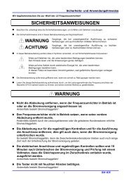
31.003-4-0076 B2<br />
31.003-4-0075 B3<br />
31.003-4-0074 B4<br />
B2: Regolazione del traferro<br />
B2: Clearance adjustment<br />
B3: Montaggio mozzo<br />
B3: Hub installation<br />
B4: Attacco leva di sblocco<br />
B4: Hand release attachment<br />
Istruzioni di montaggio<br />
Il traferro nominale “X” deve essere regolato uniformemente<br />
secondo T1 (Pag. 6) con l’aiuto dello spessimetro<br />
in assenza di corrente.<br />
L’usura, dovuta all’effetto dinamico della frenata, causa un<br />
aumento del traferro.<br />
Raccomandiamo un controllo periodico ed il ripristino del<br />
traferro al raggiungimento di Xn (T5, pag. 11) per essere<br />
sicuri che l’indotto lavori in modo corretto .<br />
La distanza dalla superficie di fissaggio stabil<strong>it</strong>a (da 0,5 a1<br />
mm) vedi B3, è stata calcolata in considerazione di qualsiasi<br />
possibile gioco dell’albero.<br />
Rispettando queste quote si ev<strong>it</strong>erà che il mozzo tocchi la<br />
superficie di fissaggio.<br />
Più questa misura è piccola, maggiore sarà l’usura consent<strong>it</strong>a<br />
prima della sost<strong>it</strong>uzione del ferodo.<br />
La leva di sblocco manuale può essere montata sul freno<br />
anche in un secondo tempo. A questo propos<strong>it</strong>o la quota<br />
(“m”) (Pag. 7, T1) è di grande importanza quando la coppia<br />
di frenatura è ridotta (Pag. 11) o quando il magnete è<br />
ecc<strong>it</strong>ato con sovratensione. In questi casi la corsa dei<br />
dischi dell’indotto può essere lim<strong>it</strong>ata dal meccanismo di<br />
sblocco manuale (dimensione “m”). L’effetto di frenatura<br />
decresce quando il traferro “Xn” (Pag. 11, T5) non è stato<br />
regolato o quando è in eccedenza.<br />
Mounting Instructions<br />
Set a uniform nominal clearance “X” according to T1,<br />
page 6 by using a feeler gauge while the brake is in a currentless<br />
state. The wear which occurs at dynamic braking<br />
causes an enlargement of the clearance. We recommend<br />
a periodic check and readjustment of the clearance after<br />
“Xn” (T5, page 11) is reached to ensure that the armature<br />
discs are attracted even under unfavorable circumstances.<br />
The distance from the attachment surface stated in B3<br />
w<strong>it</strong>h 0.5...1 mm has been selected under consideration of<br />
any possible shaft play. By means of this dimension <strong>it</strong> is<br />
being avoided that the hub rubs on the attachment surface.<br />
The smaller this dimension the larger permissible wear<br />
until replacement of the lining.<br />
A hand release can be mounted on the brake subsequently.<br />
At that the mounting dimension (T1, page 7) is of the<br />
special importance when the braking torque is reduced<br />
(page 11) or when the magnet is exc<strong>it</strong>ed w<strong>it</strong>h overcurrent.<br />
In these cases a stroke lim<strong>it</strong> of the armature discs can be<br />
achieved by the hand release device (dimension “m”). The<br />
braking effect decreases when clearance “Xn” (T5, page<br />
11) has not been readjusted or when <strong>it</strong> has been substantially<br />
exceeded.<br />
69
Decremento coppia di frenatura<br />
Braking torque decreasement<br />
*Giri della ghiera di regolazione<br />
B16<br />
*Revolution of the adjustment ring<br />
08.006-4-0361<br />
Motor size Grandezza<br />
J W Rmax W RO,1 P Rmax g min X n t 1 t 21 = t 21 ~<br />
Size<br />
[kgm 2 ] [J] [J] [J/s] [mm] [mm] [ms] [ms] [ms]<br />
56 00 0,010x10 -3 0,6x10 3 3,50x10 6 28 - - 35 12 60<br />
63 01 0,018x10 -3 0,8x10 3 5,11x10 70 5,0 0,4 40 20 45<br />
71 02 0,025x10 -3 1,0x10 3 7,50x10 6 84 5,5 0,4 45 10 32<br />
80 03 0,072x10 -3 1,6x10 3 12,50x10 6 100 6,5 0,5 55 15 50<br />
90 04 0,136x10 -3 2,1x10 3 19,10x10 6 130 8,0 0,6 90 20 95<br />
100 05 0,352x10 -3 3,8x10 3 28,00x10 6 200 10,0 0,6 100 40 200<br />
112/132 06 0,561x10 -3 6,5x10 3 28,80x10 6 250 10,0 1,0 160 60 330<br />
160 07 3,402x10 -3 11,0x10 3 35,70x10 6 266 10,0 1,0 200 70 650<br />
160 08 7,169x10 -3 20,0x10 3 44,20x10 6 330 11,0 1,2 280 70 800<br />
Dati tecnici<br />
J = momento di inerzia del mozzo e del ferodo<br />
W Rmax = lavoro di attr<strong>it</strong>o consent<strong>it</strong>o per ogni frenata<br />
W RO,1 = lavoro di attr<strong>it</strong>o per un’usura di mm 0,1<br />
P Rmax = lavoro di attr<strong>it</strong>o per secondo<br />
g min = spessore minimo consent<strong>it</strong>o del ferodo<br />
X n = traferro nominale<br />
t 1 = r<strong>it</strong>ardo di chiusura<br />
t 21 = = tempo di disinserimento con comando<br />
in corrente continua<br />
t 21 ~ = tempo di disinserimento con comando<br />
in corrente alternata<br />
I valori W Rmax e W RO,1 sono stati determinati mediante prove<br />
e applicati ad operazioni senza dischi di frizione. Veloc<strong>it</strong>à,<br />
momento di inerzia e frequenza di sw<strong>it</strong>ching sono stati<br />
attentamente selezionati per raggiungere la temperatura<br />
massima consent<strong>it</strong>a per il funzionamento.<br />
I tempi di manovra indicati (t 1 e t 21 ) valgono per il traferro<br />
(X) ed il momento torcente (M 2N ). Questi valori sono medi:<br />
eventuali variazioni possono dipendere da dispersioni nel<br />
sistema di alimentazione e dalla temperatura della bobina.<br />
Technical Data<br />
J = moment of inertia of hub and lining<br />
W Rmax = permissible friction per braking<br />
W RO,1 = friction until 0,1 mm wear is reached<br />
P Rmax = permissible friction work per second<br />
g min = min. permissible lining thickness<br />
X n = clearance, at which a readjustment is<br />
recommended<br />
t 1 = closing delay<br />
t 21 = = sw<strong>it</strong>ch-off time at d.c.-side sw<strong>it</strong>ching operations<br />
t 21 ~ = sw<strong>it</strong>ch-off time at d.c.-side sw<strong>it</strong>ching operations<br />
The values W Rmax and W RO,1 were determined through tests<br />
and apply to operation w<strong>it</strong>hout friction discs. Speed,<br />
moment of inertia and sw<strong>it</strong>ching frequency were carefully<br />
selected to attain the maximum permissible operating<br />
temperature. Depending on the actual application these<br />
values may be exceeded.<br />
The specified sw<strong>it</strong>ching times (t 1 e t 21 ) apply to nominal<br />
clearance (X) and nominal torque (M 2N ). It concerns average<br />
values whose dispersion depends on the manner of<br />
rectification and coil temperature.<br />
70
DETERMINAZIONE GRANDEZZA<br />
SIZE SELECTION<br />
Coppia di frenatura<br />
Braking torque<br />
M 2N = M erf · K<br />
M erf = M a ±M L<br />
Ma = J · α<br />
Tempo di frenatura<br />
Braking time<br />
J · ω<br />
t = + t 21<br />
M 2N ±M L<br />
Lavoro per manovra<br />
Heat load J M 2N<br />
W R = · ω 2<br />
2 M 2N ± M L<br />
W R ≤ W Rmax<br />
Lavoro di frizione per sec.<br />
Friction work<br />
P R = W R · S P R ≤ P Rmax ·<br />
Durata fino a nuova regolazione<br />
Service life until readjustment<br />
LN =<br />
(XN-X) · WRO,1<br />
0,1 · W R<br />
α = accelerazione angolare [s -2 ]<br />
J = momento di inerzia 3) [kgm 2 ]<br />
K = fattore di sicurezza (K ≥ 2) [-]<br />
L N = durata fino alla regolazione 2) [-]<br />
M a = coppia di frenatura dinamica [Nm]<br />
M erf = coppia di frenatura richiesta [Nm]<br />
M L = coppia di lavoro [Nm]<br />
M 2N = coppia nominale (T1) [Nm]<br />
P R = lavoro di frizione [J/s]<br />
t = tempo di frenatura [s]<br />
t 21 = empo di manovra (T5) [ms]<br />
W R = lavoro di attr<strong>it</strong>o [J]<br />
W Rmax = lavoro di attr<strong>it</strong>o consent<strong>it</strong>o per frenata (T5) [J]<br />
W R0,1 = lavoro di attr<strong>it</strong>o per usura di mm O,1 (T5) [J]<br />
ω = veloc<strong>it</strong>à angolare [s -1 ]<br />
X = traferro nominale (T5) [mm]<br />
X n = traferro al cui valore si raccomanda<br />
il ripristino di X (T5)<br />
[mm]<br />
1)<br />
- ML se la coppia di lavoro aiuta il processo di frenatura;<br />
+ ML se la coppia di lavoro ostacola il processo di frenatura.<br />
2)<br />
Numero di operazioni di commutazione fino alla regolazione.<br />
3)<br />
Somma dei momenti di inerzia rifer<strong>it</strong>i all’albero da frenare più<br />
il momento di inerzia del mozzo e ferodo (T5)<br />
α = angular acceleration [s -2 ]<br />
J = moment of inertia 3) [kgm 2 ]<br />
K = safety factor (K = 2) [-]<br />
L N = service life until readjustment 2) [-]<br />
M a = dynamic braking torque [Nm]<br />
M erf = required braking torque [Nm]<br />
M L = load torque [Nm]<br />
M 2N = rated torque (T1) [Nm]<br />
P R = friction work [J/s]<br />
t = braking time [s]<br />
t 21 = sw<strong>it</strong>ch-off time (T5) [ms]<br />
W R = friction [J]<br />
W Rmax = permissible friction per braking (T5)<br />
[J]<br />
W R0,1 = friction until 0,1 mm wear is reached (T5) [J]<br />
ω = angular frequency [s -1 ]<br />
X = rated air gap (T5) [mm]<br />
X n = clearance at which a readjustment<br />
is recommended (T5)<br />
[mm]<br />
1)<br />
- ML is the load torque supports the braking process;<br />
+ ML, if the load torque counteracts the braking process.<br />
2)<br />
Number of sw<strong>it</strong>ching operations until readjustment.<br />
3)<br />
Sum of the moment of inertia related to the shaft to the braked<br />
plus the moment of inertia of the hub-lining-system (T5).<br />
71
Interruzione corrente lato continua<br />
DC-side sw<strong>it</strong>ching<br />
Interruzione corrente lato alternata<br />
AC-side sw<strong>it</strong>ching<br />
Diagramma corrente/coppia/tempo<br />
Current-Torque-Time-Diagram<br />
IN<br />
M 2N<br />
t 1<br />
t21<br />
= Corrente nominale del magnete<br />
= Coppia nominale<br />
= R<strong>it</strong>ardo di chiusura<br />
= Tempo di sgancio<br />
IN<br />
M2N<br />
t1<br />
t21<br />
= Rated magnet current<br />
= Nominale torque<br />
= Closing delay<br />
= Sw<strong>it</strong>ch-off time<br />
I valori W Rmax e W RO,1 sono stati determinati mediante prove<br />
e applicati ad operazioni senza dischi di frizione. Veloc<strong>it</strong>à,<br />
momento di inerzia e frequenza di sw<strong>it</strong>ching sono stati<br />
attentamente selezionati per raggiungere la temperatura<br />
massima consent<strong>it</strong>a per il funzionamento.<br />
I tempi di manovra indicati (t 1 e t 21 ) valgono per il traferro<br />
(X) ed il momento torcente (M 2N ). Questi valori sono medi:<br />
eventuali variazioni possono dipendere da dispersioni nel<br />
sistema di alimentazione e dalla temperatura della bobina.<br />
The values W Rmax and W RO,1 were determined through tests<br />
and apply to operation w<strong>it</strong>hout friction discs. Speed,<br />
moment of inertia and sw<strong>it</strong>ching frequency were carefully<br />
selected to attain the maximum permissible operating temperature.<br />
Depending on the actual application these values<br />
may be exceeded. The specified sw<strong>it</strong>ching times (t 1 and t 21 )<br />
apply to nominal clearance (X) and nominal torque (M 2N ). It<br />
concerns average values whose dispersion depends on<br />
the manner of rectification and coil temperature.<br />
72
DATI TECNICI<br />
TECHNICAL DATA<br />
Lavoro di attr<strong>it</strong>o ammesso WRmax [J]<br />
in funzione della frequenza<br />
di commutazione<br />
Valido solo per i giri/minuto indicati<br />
da 00.08. fino a 07.08. - 3000 min -1<br />
da 08.08. fino a 10.08. - 1500 min -1<br />
Linea rossa per freni senza disco frizione.<br />
Permissible friction WRmax [J]<br />
depending on the sw<strong>it</strong>ching frequency<br />
Valid only for the stated revolutions<br />
per minute<br />
00.08. bis 07.08. - 3000 min -1<br />
08.08. bis 10.08. - 1500 min -1<br />
Red line for brakes w<strong>it</strong>hout friction disk.<br />
I valori di WRmax sono validi per freni standard e per una<br />
seconda superficie di attr<strong>it</strong>o di ghisa grigia. A seconda<br />
dell’applicazione, si possono superare o rimanere al di<br />
sotto dei presenti valori.<br />
Dischi frizione inossidabili, o veloc<strong>it</strong>à superiori a quelle<br />
specificate nel diagramma, riducono notevolmente il lavoro<br />
di attr<strong>it</strong>o ammesso della frizione.<br />
Se la coppia nominale del freno viene ridotta girando l’anello<br />
di regolazione, il lavoro di attr<strong>it</strong>o aumenta.<br />
The values for WRmax are valid for standard brakes and a<br />
second friction surface of casting. Depending on application<br />
these values may be exceeded or remained under.<br />
Rustfree friction discs, or speeds higher than specified in<br />
the diagram, reduce the permissible friction work considerably.<br />
If the rated torque of the brake is reduced by turning the<br />
adjustment ring the permissible friction work increases.<br />
Size max. speed J W zul g min X n<br />
Operating Stop Emergency Stop<br />
[min -1 ] [min -1 ] [10 -3 kgm 2 ] [J] [mm] [mm]<br />
00 3000 6000 0,01 700 - -<br />
01 - - 0,018 1300 5,0 0,4<br />
02 - - 0,025 1700 5,5 0,4<br />
03 - - 0,072 2000 6,5 0,5<br />
04 - 6000 0,136 5000 8,0 0,6<br />
05 - 5000 0,35 7000 10,0 0,6<br />
06 - 5000 0,56 10000 10,0 1,0<br />
07 - 4500 1,57 13000 10,0 1,0<br />
08 3000 3500 5,92 17000 11,0 1,2<br />
09 1500 3000 7,38 20000 12,0 1,2<br />
10 1500 3000 20,54 25000 14,0 1,5<br />
73
DISPOSIZIONI COMMUTAZIONE<br />
Commutazione lato AC<br />
Quando si commuta a monte il raddrizzatore sul lato AC il<br />
campo magnetico decade lentamente. Con questo modo<br />
di commutazione il r<strong>it</strong>ardo di apertura è abbastanza<br />
lungo.<br />
La commutazione lato AC non necess<strong>it</strong>a di alcun sistema<br />
di protezione per la bobina e per i contatti di commutazione.<br />
Alla disconnessione i diodi raddrizzatori agiscono<br />
come diodi ad oscillazione libera.<br />
I tempi di commutazione t11 per la commutazione lato AC<br />
indicati a pagina 20 aumentano quando il raddrizzatore<br />
viene collegato direttamente alla morsettiera del motore<br />
2. Quando il motore rallenta viene applicata una tensione<br />
generatoriale ai morsetti del motore. Questo collegamento<br />
non è permesso per il funzionamento con invert<strong>it</strong>ore di<br />
frequenza.<br />
Per lunghezze di linea di oltre 10 m. tra il raddrizzatore e<br />
il freno per la commutazione lato AC le norme prescrivono<br />
l’uso di un interruttore separato 1. In questo caso la tensione<br />
di alimentazione può non essere presa dietro al relé<br />
motore 2. Se non è possibile installare un ulteriore interruttore<br />
diventa necessario l’uso di raddrizzatori speciali.<br />
Diagramma Tempo-Corrente<br />
Current-Time/Voltage-Time/Torque-Time Diagram<br />
SWITCHING ARRANGEMENTS<br />
AC-side Sw<strong>it</strong>ching<br />
When sw<strong>it</strong>ching before the rectifier on the AC-side the<br />
magnetic field decays slowly. At this mode of sw<strong>it</strong>ching<br />
the tripping delay is qu<strong>it</strong>e long.<br />
The AC-side sw<strong>it</strong>ching requires no protective measurements<br />
for the coil and the sw<strong>it</strong>ching contacts. On disconnection<br />
the rectifier diodes act as free-wheeling diodes.<br />
The sw<strong>it</strong>ching times t11 for AC-side sw<strong>it</strong>ching quoted on<br />
page 20 increase when the rectifier is connected directly<br />
in the motor terminal box 2. When the motor slows down<br />
a generatoric voltage is applied to the motor terminals.<br />
This wiring is not perm<strong>it</strong>ted for frequency inverter operation.<br />
For line lengths of more than 10 m. between rectifier and<br />
brake at AC-side sw<strong>it</strong>ching the regulations prescribe the<br />
use of a separate sw<strong>it</strong>ch 1. In this case the supply voltage<br />
may not be tapped behind the motor contactor 2. If <strong>it</strong> is<br />
not possible to install an add<strong>it</strong>ional sw<strong>it</strong>ch the use of special<br />
rectifiers becomes necessary.<br />
Tempo-Tensione/Tempo-Coppia nominale<br />
Wiring diagram<br />
t1<br />
t11<br />
t2<br />
= Tempo di inserimento<br />
= R<strong>it</strong>ardo della risposta all’inserimento<br />
= Tempo di disconnessione (disinnesto)<br />
t1<br />
t11<br />
t2<br />
= Engaging time<br />
= Engagement delay time<br />
= Release time<br />
74
DISPOSIZIONI COMMUTAZIONE<br />
Commutazione lato DC<br />
La commutazione avviene tra il raddrizzatore e il magnete.<br />
Con questo modo di commutazione il r<strong>it</strong>ardo di apertura<br />
è breve, poiché l’energia del campo magnetico viene<br />
assorb<strong>it</strong>a dal raddrizzatore. I picchi di tensione che si verificano<br />
alla commutazione sono lim<strong>it</strong>ati ad un livello innocuo<br />
per il raddrizzatore.<br />
La frequenza di commutazione massima permessa per la<br />
commutazione lato DC dei raddrizzatori dipende dal contenuto<br />
di energia del magnete ed è specificata nella<br />
Tabella T8 per il KEB COMBISTOP. Frequenze di commutazione<br />
più elevate vengono raggiunte dalla connessione<br />
esterna di un varistore in parallelo al freno o ai terminali<br />
+ e - DC del raddrizzatore.<br />
Raddrizzatore Articolo KEB Varistore<br />
02.91. 00.90.045-2752 S20K275<br />
04.91. 00.90.045-5101 S20K510<br />
05.91. 00.90.045-6252 S20K625<br />
06.91. 00.90.045-4202 S20K420*<br />
*2 componenti in serie<br />
La commutazione contemporanea lato AC e DC, mostrata<br />
nell’esempio 4 garantisce tempi di disconnessione brevi e<br />
riduce il consumo del contatto.<br />
Diagramma Tempo-Corrente<br />
Current-Time/Voltage-Time/Torque-Time Diagram<br />
SWITCHING ARRANGEMENTS<br />
DC-side Sw<strong>it</strong>ching<br />
The sw<strong>it</strong>ching is done between the rectifier and the<br />
magnet. At this mode of sw<strong>it</strong>ching the tripping delay is<br />
short, since the energy of the magnetic field is absorbed<br />
by the rectifier. The voltage peaks that occur at sw<strong>it</strong>ching<br />
are lim<strong>it</strong>ed to a harmless level for the rectifier.<br />
The maximal permissible sw<strong>it</strong>ching frequency for the DCside<br />
sw<strong>it</strong>ching of rectifiers depends on the energy content<br />
of the magnet and is specified in Table T8 for KEB COM-<br />
BISTOP.<br />
Higher sw<strong>it</strong>ching frequencies are achieved by the external<br />
connection of a varistor in parallel to the brake or to the<br />
terminals + and - DC of the rectifier.<br />
Rectifier KEB-Article Varistor<br />
02.91. 00.90.045-2752 S20K275<br />
04.91. 00.90.045-5101 S20K510<br />
05.91. 00.90.045-6252 S20K625<br />
06.91. 00.90.045-4202 S20K420*<br />
* 2 components in series<br />
The simultaneous AC and DC-side sw<strong>it</strong>ching, shown in<br />
example 4 guarantees short disconnecting times and<br />
reduces the contact erosion.<br />
Tempo-Tensione/Tempo-Coppia nominale<br />
Wiring diagram<br />
t1<br />
= Tempo di inserimento<br />
t1<br />
= Engaging time<br />
t11<br />
= R<strong>it</strong>ardo della risposta all’inserimento<br />
t11<br />
= Engagement delay time<br />
t2<br />
= Tempo di disconnessione (disinnesto)<br />
t2<br />
= Release time<br />
75
CICLI DI COMMUTAZIONE E<br />
TEMPI DI COMMUTAZIONE<br />
SWITCHING CYCLES<br />
AND SWITCHING TIMES<br />
Cicli di commutazione Commutazione Ac Commutazione DC<br />
Sw<strong>it</strong>ching cycles AC-sw<strong>it</strong>ching DC-sw<strong>it</strong>ching<br />
Dimensioni M2N P20 SC1 SC2 t2 t11 ~ t1 ~ t11 = t1 =<br />
Size [Nm] [W] [1/min] [1/min] [ms] [ms] [ms] [ms] [ms]<br />
00 1 11 70 140 35 60 100 12 25<br />
01 3 16 55 110 40 60 120 15 30<br />
02 4 20 60 120 40 40 90 10 20<br />
03 8 25 40 75 60 80 140 15 30<br />
04 16 30 40 75 100 140 200 20 50<br />
05 32 40 25 50 120 180 240 25 55<br />
06 60 52 5 10 240 200 330 25 90<br />
07 100 65 5 10 240 400 650 50 150<br />
08 150 75 5 10 300 700 900 60 180<br />
09 200 75 2 5 350 900 1200 60 220<br />
10 400 130 1 3 350 1400 1800 60 250<br />
SC1<br />
applicabile per raddrizzatori:<br />
SC1<br />
applicable for rectifiers:<br />
02.91.010-CE07<br />
02.91.020-CE07<br />
02.91.010-CEMV<br />
02.91.010-CE07<br />
02.91.020-CE07<br />
02.91.010-CEMV<br />
SC2<br />
applicabile per raddrizzatori:<br />
SC2<br />
applicable for rectifiers:<br />
04.91.010-CE07<br />
04.91.020-CE07<br />
05.91.010-CE09<br />
06.91.010-CE09<br />
04.91.010-CE07<br />
04.91.020-CE07<br />
05.91.010-CE09<br />
06.91.010-CE09<br />
SC<br />
t1<br />
t11<br />
t2<br />
Ciclo di commutazione massimo permesso con commutazione<br />
sul lato DC, funzionamento continuo e<br />
temperatura massima di funzionamento di 80 °C.<br />
[min -1 ]<br />
Tempo di inserimento<br />
Tempo tra la disconnessione della corrente e il raggiungimento<br />
della coppia nominale.<br />
[ms]<br />
R<strong>it</strong>ardo della risposta<br />
Tempo tra la disconnessione della corrente e l’aumento<br />
della coppia nominale.<br />
[ms]<br />
Tempo tra la connessione della corrente e l’inizio<br />
della diminuzione della coppia nominale. [ms]<br />
SC<br />
t1<br />
t11<br />
t2<br />
Maximal permissible sw<strong>it</strong>ching cycle at DC-side sw<strong>it</strong>ching<br />
and max, operating temperature of 80 °C. [min -<br />
1<br />
]<br />
Engaging time<br />
Time from disconnecting the current to attaining the<br />
rated torque.<br />
[ms]<br />
Engagement delay time<br />
Time from disconnecting the current to the rise of the<br />
torque.<br />
[ms]<br />
Release time<br />
Time from connecting the current to the beginning of<br />
torque decrease.<br />
[ms]<br />
t3<br />
Tempo di scorrimento<br />
t3<br />
Slip time<br />
Tempo tra l’inizio dell’aumento della coppia nominale<br />
e il raggiungimento del momento di sincronizzazione.<br />
[ms]<br />
Time from the beginning of the torque rise until attaining<br />
the moment of sychronization.<br />
[ms]<br />
I tempi di commutazione indicati corrispondono alle<br />
norme DIN VDE 580 (10.94)<br />
The designation of the sw<strong>it</strong>ching times corresponds to<br />
DIN VDE 580 (10.94).<br />
76
RADDRIZZATORI CONFORMI CE<br />
CE CONFORM RECTIFIERS<br />
U in<br />
Interruzione<br />
U vmax<br />
U in<br />
Sw<strong>it</strong>ching<br />
U vmax<br />
Uin<br />
Uvmax<br />
Uout<br />
WS<br />
GS<br />
IN (45 °C)<br />
Tensione massima di entrata<br />
Tensione massima di spegnimento<br />
Tensione di usc<strong>it</strong>a DC (corrente continua)<br />
Commutazione lato AC (corrente alterna)<br />
Commutazione lato DC (corrente continua)<br />
Corrente nominale alla temperatura indicata<br />
Uin<br />
Uvmax<br />
Uout<br />
WS<br />
GS<br />
IN (45 °C)<br />
maximum input voltage<br />
maximum sw<strong>it</strong>ch-off voltage<br />
DC output voltage<br />
AC side sw<strong>it</strong>ching<br />
DC side sw<strong>it</strong>ching<br />
nominal current at stated temperature<br />
Sezione trasversale morsetto 1,5 mm 2<br />
Sezione trasversale morsetto 2,5 mm 2<br />
Terminal cross section 1,5 mm 2 Terminal cross section 2,5 mm 2<br />
77
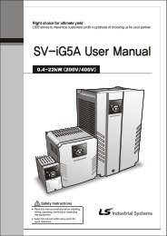
1 COVER FAN<br />
2 SCREW M4x9<br />
3 PLASTIC FAN<br />
4 ASSEMBLY BRAKE SCREW<br />
5 BRAKE<br />
6 HAND RELASE<br />
7 HUB<br />
8 FRICTION<br />
9 BOTTOM FLANGE<br />
10 SPRING<br />
11 BEARING<br />
12 SEGER<br />
13 MOTOR SHAFT WITH ROTOR<br />
14 BRAKE KEY<br />
15 ROTOR<br />
16 DRIVE KEY<br />
17 DRIVE BEARING<br />
18 ALUMINIUM CASE<br />
19 ASSEMBLY MOTOR SCREW<br />
20 TERMINAL BOARD<br />
78<br />
21 ASSEMBLY SCREW M4x12<br />
22 TERMINAL BOX<br />
23 RECTIFIER<br />
24 COVER BOX<br />
25 ASSEMBLY COVER BOX SCREW<br />
26 WINDING ON STATOR<br />
27 MOUNTING FLANGE<br />
28 SEAL